
Lecture
|
5.1. Physical Foundations of the Operation of Electrical Sensors We classify as electrical sensors those sensors whose primary signals appear in the form of a change in the electrical properties of physical bodies, substances or the electrical circuits associated with them. Electrical sensors, in a number of cases, may be constituent parts of other sensors; in such cases they are usually regarded as "transducers", – converters of other kinds of signals into electrical form.
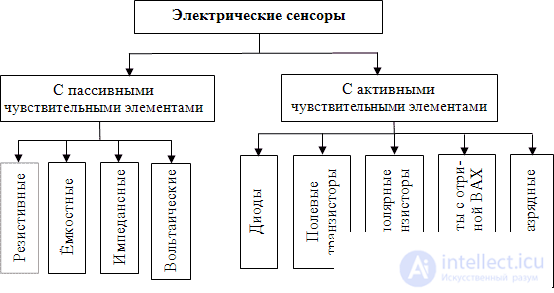
Classification of electrical sensors By the physical operating principle of the sensing element, electrical sensors are usually classified (fig. 5.1) into sensors with passive and with active sensing elements.
Fig. 5.1. Classification of electrical sensors by physical operating principle Active sensing elements include transistors, diodes, nonlinear electronic elements having sections of the current-voltage characteristic with a negative slope, gas-discharge elements and other elements inside which small changes caused by an external influence are immediately and considerably amplified at the expense of an external energy source.
|
|
|
|
|
|
5.2. Resistive sensors Among the simplest electrical sensors are resistive sensors, in which the resistance of one or another section of an electrical circuit changes under the action of an external factor. As already stated above, we shall classify them on the basis of the external factor under whose action the electrical resistance of the resistor changes. Thermoresistors Sensors– thermoresistors, in which the electrical resistance of a conductor or semiconductor depends on temperature. The accuracy of temperature measurement using thermoresistors depends on a number of factors. From the standpoint of thermal physics a thermoresistor is characterized by its own heat capacity Usually the heat capacity In fact a thermoresistor is not always at a temperature coinciding with the temperature of the object. After all, it exchanges heat not only with the object whose temperature it is meant to measure, but also with the surrounding medium and with the measurement circuit. Using the well-known thermal-electrical analogy, the equivalent thermal-electrical circuit of the measurement can be represented in the form shown in fig. 5.2.
Fig. 5.2. Equivalent thermal-electrical circuit for temperature measurement Calculation of this circuit in the steady-state regime, i.e. in the state of already-established thermal equilibrium, gives the following formula for the temperature measured by the temperature sensor
where From this it is clear that the sensor will correctly measure the temperature of the object only on condition that It should be remembered that t = T- T0 , where t –is the temperature in Celsius; T - is the temperature in Kelvin; T0 = 273.15K, From the circuit shown in fig. 5.2, it also follows that when the temperature of the object changes rapidly, the response of the thermoresistor to these changes will depend on its thermal inertia. It is characterized by the time constant It is known that the electrical resistance of metals increases with rising temperature according to the law known from the school physics course:
where Thermistors Semiconductors have considerably larger temperature coefficients of electrical resistance, which can be of either sign. Semiconductor thermoresistors are commonly called thermistors. Photoresistors The next type of resistive sensors is photoresistors. Their electrical resistance depends on illumination. Photoresistors are most often made from group
|
|
|
|
|
If a force acts on a metal wire that stretches it, then as a result of the deformation the length of the wire increases somewhat, while the cross-sectional area decreases somewhat. Because of this the electrical resistance of the wire increases. This phenomenon is called the piezoresistive (from the Greek root) or the strain-resistive (from the Latin root) effect.
Semiconductor piezoresistors have considerably higher strain sensitivity than metallic ones, since the mechanism of the change in electrical resistance in them is much more complex. The strain sensitivity of resistors made, for example, of silicon is tens of times higher than that of metallic ones.
Magnetoresistive sensors make use of the ability of certain materials to substantially change their electrical conductivity depending on the direction and strength of an external magnetic field. Such materials include, for example, permalloy films ( ). Most often a structure is used in which the sensing element consists of 4 thin-film permalloy resistors deposited on the surface of silicon and connected in the form of a bridge measuring circuit.
Changes in the electrical capacitance of sensing elements under the influence of factors that need to be monitored are no less widely used for creating sensors. In fig. 5.3, as an example, a longitudinal section is shown of a cylindrical capacitor in which the inner cylindrical electrode 1 can move along the axis of the cylinder relative to the outer cylindrical electrode 2.

Fig. 5.3 Cylindrical capacitor with a movable core as a linear displacement sensor
The electrical capacitance of a cylindrical capacitor, as is known, is described by the formula
|
|
(5.3) |
where  – is the electric constant;
  and
and  – are the radii of the inner and outer plates of the capacitor;
  – is the length of the interaction zone of the cylinders. Therefore, over a sufficiently wide range the capacitance is proportional to the length
  , i.e. it is a linear function of the displacement of the core. Such capacitors are successfully used for the precise conversion into an electrical signal of the relative position and displacement of bodies.
The electrical capacitance of a parallel-plate capacitor is, as is known, described by the formula
|
|
(5.4) |
where  – is the area of its plates;
  – is the distance between them;
  – is the permittivity of the material between the plates. A change in any of these quantities leads to a change in capacitance and can thus be recorded. For example, in classical variable capacitors one group of metal plates shifts relative to the other when rotated about an axis. This changes their area of interaction
  and, correspondingly, the electrical capacitance. Such a capacitor can be used, for example, as a sensing element in a rotation angle sensor.
. Examples of capacitive electrical sensors are: a) a linear displacement sensor, in which the capacitance of a cylindrical capacitor changes as its inner rod moves; b) a pressure sensor, in which the capacitance of a parallel-plate capacitor changes when the external pressure changes and, correspondingly, the distance between the plates; c) a liquid level sensor, in which the capacitance of the measuring capacitor directly depends on the level of the liquid; d) comb-type gas sensors, in which the capacitance between two comb-shaped electrodes changes depending on the presence and concentration in the atmosphere of molecules of certain vapours or gases.
In many substances, under the action of external factors, not only the permittivity changes but also the electrical conductivity. In general such substances are usually characterized by a complex permittivity. And the gap between the electrodes is in this case characterized by impedance – the complex electrical resistance to alternating current. Structurally, impedance sensing elements are made in the same way as capacitive ones. But measurements are carried out on alternating current of an optimally chosen frequency. By passing an alternating electric current of the appropriate frequency through them, it is possible to measure not only the absolute value of the impedance, but also the phase shift between the current and the voltage across the sensing element, which provides additional information.
Self-check questions 5
By what principle are electrical sensors classified?
What is a "transducer"? Why are electrical sensors often used as transducers?
What are "thermoresistors"? Is there a difference between "thermoresistors" and "thermistors"?
What are "photoresistors"? Explain the physical mechanism of their operation. What is the "spectral characteristic" of a photoresistor?
What are "piezoresistors"? What are they used for?
What are "magnetoresistive sensors"? From what material are they mostly made?
Give examples of capacitive electrical sensors.
What is the difference between capacitive and impedance sensors?


 and its own heat generation
  , where
  – is the value of the electric current flowing through the thermoresistor,
  – its electrical resistance. The quantity
  is also called the "self-heating power" of the thermoresistor. The self-heating temperature t depends on the dissipated power and the dissipation coefficient.
 of a thermoresistor is smaller, the smaller its mass.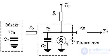

 (5.1)
(5.1) – are the thermal resistances between the temperature sensor and the object, the temperature sensor and the surrounding medium, and the temperature sensor and the measurement circuit, respectively;
  – are the absolute temperatures of the object, the surrounding medium and the measurement circuit, respectively; t-is the self-heating temperature.
 and
and  , i.e. if the thermoresistor is in close thermal contact with the object, is well thermally insulated from the surrounding medium and from the measurement circuit, and if the measuring current is sufficiently small.
 . For the temperature measurement to have low inertia, the heat capacity of the thermoresistor CT should be as small as possible, and its thermal contact with the object as good as possible. Let us emphasize that these considerations apply not only to thermoresistors, but to all other temperature sensors as well.

 (5.2)
(5.2) – is the resistance of the conductor at the given temperature
  – is the resistance of the same conductor at the absolute temperature
  – is the temperature coefficient of resistance. All metals have a positive temperature coefficient of resistance. To reduce heat capacity, metal thermoresistors are usually made in the form of very thin wires or films. Platinum, tungsten and nickel are most often used, as they have a high melting point and are distinguished by their chemical, thermal and mechanical resistance and long-term stability. However, their temperature coefficients of resistance are relatively small.
 semiconductors by depositing thin layers or applying thick layers with subsequent sintering of the plates, less often – from single crystals. The change in their electrical resistance under the action of light occurs owing to the internal photoelectric effect, i.e. owing to the fact that, upon absorption of light quanta in the semiconductor, additional free electric charge carriers appear.





Comments