
Lecture
A universal voltmeter is a measuring instrument designed to determine electrical voltage across various ranges and conditions. Unlike specialized voltmeters, which can measure only direct or alternating voltage, universal models are able to work with both types of voltage and may have additional functions, such as measuring resistance, frequency and even capacitance. Some models can also measure capacitance, temperature, magnetic field and perform continuity testing of circuits.
A multimeter (from the English multimeter), a tester (from the English test) — a device for measuring a range of parameters of direct or alternating current, the main ones being voltage, current and resistance (see avometer). A multimeter is also used to check the continuity of an electrical circuit (the “continuity test” function).
The name “multimeter” first became established specifically for digital meters, while analog instruments are often colloquially called a “tester”, an “avometer”, and sometimes simply a “Tseshka” (from the name of the Soviet series of instruments “Ts-xxxx”).
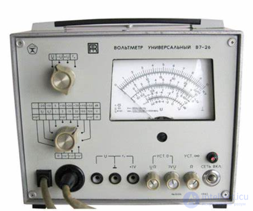
A universal office (industrial) voltmeter.
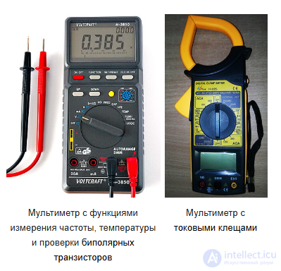
Portable multimeters
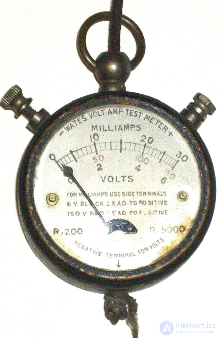
A pocket multimeter from the 1920s
A universal voltmeter works by converting the input electrical signal into a reading on the display. The main components of the instrument include:
Input probes – used to connect to the circuit being measured.
ADC (analog-to-digital converter) – converts the analog signal to digital.
Processor and display – responsible for processing the data and displaying the results.
Range switch – allows selection of the required voltage measurement level.
There are analog and digital universal voltmeters.
Analog devices have a needle indicator and are distinguished by high accuracy when measuring small changes in voltage.
Digital models have a digital display and provide more accurate and convenient measurements, often equipped with automatic range selection.
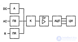
Fig.19. Functional diagram of a multimeter
· commutator K of the measured signals;
· operational amplifier OA;
· analog-to-digital converter ADC;
· digital indicator DI.
Various measuring transducers are connected to the inputs of the commutator.
The first – attenuator A – is used to convert a high-level direct voltage into a lower-level direct voltage.
The second – precision rectifier PR – is used to convert an alternating voltage (current) into a direct voltage.
The third converter PR converts resistance into a direct voltage. Most often this is simply a precision direct-current source, which is fed through the resistance being measured and creates a voltage drop U = IR across it.
Thus, a multimeter can measure voltage (and currents) of direct and alternating current, as well as resistance. The more converters a multimeter contains, the more complex its electronic circuitry and the more expensive the instrument. It should be noted, however, that specialized integrated circuits are manufactured for building typical digital multimeters, containing practically all of the units mentioned. This is precisely why multimeters, even from different manufacturers, are often similar in metrological and electrical characteristics “like two peas in a pod”. They usually differ in display resolution and error. The smaller the latter, the more expensive the instrument tends to be, and the larger its dimensions and mass. This is related to the use of precision resistors and capacitors, whose dimensions and mass are noticeably greater than those of ordinary components.
Some multimeters are equipped with simple means for continuity testing of circuits with audible indication (if the circuit resistance is less than a set value in tens of ohms), testing of chips of various logic families, and checking diodes and transistors. The latter is usually implemented by setting a stable small current into the base and measuring the collector current. It is proportional to the base current transfer ratio B (or hFE).
Sometimes multimeters are equipped with means for testing logic chips and even a simple test-signal generator at several frequencies.
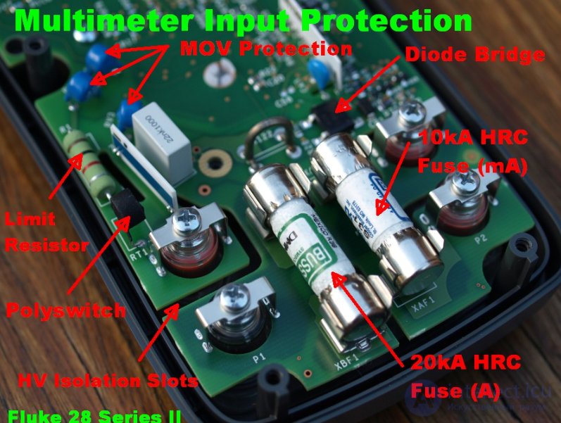
Example of input protection on a multimeter
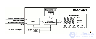
Fig.15. Block diagram of a multimeter
The instrument includes: current and voltage measurement inputs, an analog-to-digital converter (ADC), a microcontroller that processes the input signal, a four-digit LED digital display, individual LED indicators, a measurement mode switch button, and a secondary power supply (SPS) with galvanic isolation.
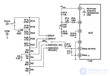
Fig.16. Simplified diagram of a multimeter in voltage-measurement mode
The simplified diagram of a multimeter in voltage-measurement mode is shown in fig. 2. When measuring direct voltage, the input signal is applied to R1...R6, from whose output, through the switch (per circuit 1-8/1... 1-8/2), it is applied to the protective resistor R17. This resistor, in addition, together with capacitor C3, forms a low-pass filter when measuring alternating voltage. The signal then goes to the non-inverting input of the ADC chip, pin 31. The inverting input of the chip is supplied with the common-lead potential produced by the 3 V regulated voltage source, pin 32. When measuring alternating voltage, it is rectified by a half-wave rectifier on diode D1. Resistors R1 and R2 are selected so that, when measuring sinusoidal voltage, the instrument shows the correct value. ADC protection is provided by divider R1...R6 and resistor R17.
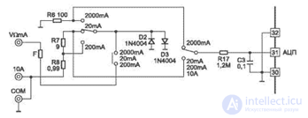
Fig.17. Simplified diagram of a multimeter in current-measurement mode
The simplified diagram of a multimeter in current-measurement mode is shown in fig. 3. In direct-current measurement mode, the current flows through resistors R0, R8, R7 and R6, switched depending on the measurement range. The voltage drop across these resistors, through R17, is applied to the ADC input, and the result is displayed. ADC protection is provided by diodes D2, D3 (in some models these may not be installed) and fuse F.
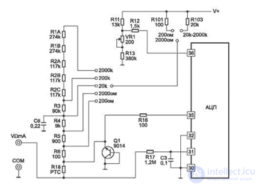
Fig.18. Simplified diagram of a multimeter in resistance-measurement mode
The simplified diagram of a multimeter in resistance-measurement mode is shown in fig. 4. In resistance-measurement mode, the dependence expressed by formula (2) is used. The diagram shows that one and the same current from the source of voltage +Uin flows through the reference resistor Ron and the measured resistor Rx (the input currents at 35, 36, 30 and 31 are negligibly small), and the ratio of Uin to Uon is equal to the ratio of the resistances of Rx and Ron. R1....R6 are used as reference resistors, and R10 and R103 are used as current-setting resistors. ADC protection is provided by thermistor R18 (in some cheaper models ordinary resistors of 1...2 kΩ are used), transistor Q1 in Zener-diode mode (not always fitted), and resistors R35, R16 and R17 at inputs 36, 35 and 31 of the ADC.
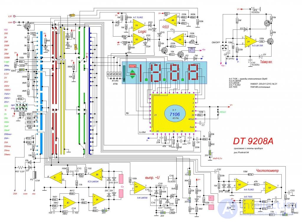
fig. example of a complete diagram of a typical multimeter
The resolution of a multimeter is the smallest part of the scale that can be displayed, which depends on the range setting. On some digital multimeters it can be adjusted, with higher-resolution measurements taking longer. For example, a multimeter with a resolution of 1 mV on the 10 V range can show changes in measurements in steps of 1 mV. Absolute accuracy is the measurement error compared to an ideal measurement. Relative accuracy is the measurement error compared to the device used to calibrate the multimeter. Most multimeter datasheets specify relative accuracy. To calculate absolute accuracy from the multimeter's relative accuracy, add the absolute accuracy of the device used to calibrate the multimeter to the multimeter's relative accuracy.
The resolution of a multimeter is often given as the number of decimal digits that are permitted and displayed. If the most significant digit cannot take all values from 0 to 9, it is usually called a fractional digit, which is confusing. For example, a multimeter that can read up to 19999 (plus a built-in decimal point) is considered to read 4+1⁄2 digits. By convention, if the most significant digit can be 0 or 1, it is called a half digit; if it can take higher values without reaching 9 (often 3 or 5), it can be called a three-quarter digit. A 5+1⁄2-digit multimeter will display one “half digit”, which can display only 0 or 1, followed by five digits taking all values from 0 to 9. Such a meter can show positive or negative values from 0 to 199999. A 3+3⁄4-digit meter can display a count from 0 to 3999 or 5999, depending on the manufacturer. Although the digital display can easily be extended in resolution, additional digits are of no value unless accompanied by care in the design and calibration of the multimeter's analog sections. Meaningful (i.e. high-precision) measurements require a good understanding of the instrument's specifications, good control of measurement conditions, and traceability of the instrument's calibration. However, even if its resolution exceeds its accuracy, a meter can be useful for comparing measurements. For example, a reading of 5+1⁄2 stable digits might indicate that one nominally 100 kΩ resistor is about 7 Ω larger than another, even though the error of each measurement is 0.2% of reading plus 0.05% of full scale. Specifying the “display count” is another way to state resolution. The display count gives the largest number, or the largest number plus one (to include the all-zeros display), that the multimeter's display can show, ignoring the decimal separator. For example, a 5+1⁄2-digit multimeter can also be specified as a multimeter with 199999 counts of display, or 200000 counts of display. Often the display count is simply called the “count” in multimeter specifications. The accuracy of a digital multimeter can be specified in a two-term form, for example, “±1% of reading +2 counts”, reflecting the various sources of error in the instrument.
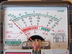
Display of an analog multimeter
Analog meters are of older design, and although they are technically surpassed by digital meters with bar-graph displays, they may still be preferred by engineers and troubleshooters. One reason is that analog meters are more sensitive (or responsive) to changes in the circuit being measured. A digital multimeter samples the measured quantity over time and then displays it. Analog multimeters continuously read the test value. If there are small changes in the reading, the needle of an analog multimeter will try to track them, unlike a digital meter, which has to wait for the next sample, giving delays between each discrete reading (plus a digital meter may additionally need settling time to converge on a value). The value on a digital display, unlike an analog display, is subjectively harder to read at a glance. This continuous-tracking feature becomes important, for example, when testing capacitors or coils. A properly functioning capacitor should allow current to flow when voltage is applied, after which the current slowly decreases to zero, and this “signature” is easy to see on an analog multimeter but not on a digital multimeter. This is similar to testing a coil, except that the current starts low and increases. Resistance measurements on an analog meter, in particular, can have low accuracy due to the typical resistance-measurement circuit, which heavily compresses the scale at higher resistance values. Inexpensive analog meters may have only a single resistance scale, which severely limits the range of accurate measurements. Usually an analog meter has an adjustment panel for setting the meter's zero-resistance calibration, to compensate for the changing voltage of the meter's battery and the resistance of the meter's test leads.
Digital multimeters typically perform measurements with an accuracy exceeding that of their analog counterparts. Standard analog multimeters measure with an accuracy typically of ±3%, although instruments with higher accuracy are produced. Standard handheld digital multimeters have an accuracy typically of ±0.5% on DC voltage ranges. Basic benchtop multimeters are available with a specified accuracy better than ±0.01%. Laboratory instruments can have an accuracy of a few parts per million.
Accuracy figures should be interpreted with care. The accuracy of an analog instrument usually refers to full-scale deflection; a reading of 30 V on the 100 V range of a 3% meter is subject to an error of 3 V, i.e. 10% of the reading. Digital meters usually state accuracy as a percentage of reading plus a percentage of the full-scale value, sometimes expressed in units rather than in percent.
The stated accuracy is given as the accuracy of the lowest DC millivolt (mV) range and is known as the “basic DC voltage accuracy”. Higher DC voltage, current, resistance, AC and other ranges usually have lower accuracy than the basic DC voltage figure. AC measurements meet the stated accuracy only within the specified frequency range.
Manufacturers may provide calibration services, thanks to which new meters can be purchased with a calibration certificate confirming that the meter has been adjusted in accordance with standards traceable, for example, to the standards of the U.S. National Institute of Standards and Technology (NIST) or another national standards organization.
Test equipment tends to drift out of calibration over time, and the stated accuracy cannot be relied on indefinitely. For more expensive equipment, manufacturers and third parties provide calibration services so that older equipment can be recalibrated and recertified. The cost of such services is disproportionate for inexpensive equipment; however, for most ordinary tests, extreme accuracy is not required. Multimeters used for critical measurements may be part of a metrology program to ensure calibration.
A multimeter can be considered “average-responding” to AC waveforms unless it is stated to be of the “true RMS” type. An average-responding multimeter will meet its stated accuracy only for AC volts and amps with purely sinusoidal waveforms. A true-RMS multimeter, on the other hand, will meet its stated accuracy for AC volts and current with any type of waveform up to a specified crest factor; RMS performance is sometimes claimed for meters that report accurate RMS readings only at certain (usually low) frequencies and with certain waveforms (essentially, always sine waves).
The accuracy of a meter's AC voltage and current measurement can have different characteristics at different frequencies.
When used to measure voltage, the input resistance of the multimeter must be very high compared to the resistance of the circuit being measured; otherwise the operation of the circuit may be disturbed and the readings will be inaccurate. Meters with electronic amplifiers (all digital multimeters and some analog meters) have a fixed input resistance that is high enough not to disturb most circuits. This is often one or ten MΩ; standardization of input resistance allows the use of external high-resistance probes, which form a voltage divider with the input resistance to extend the voltage range up to tens of thousands of volts. High-quality multimeters typically provide an input resistance of more than 10 GΩ for ranges less than or equal to 10 V. Some high-end multimeters provide a resistance >10 GΩ for ranges exceeding 10 V. Most moving-needle analog multimeters have no buffer and draw current from the circuit under test to deflect the meter needle. The resistance of the meter varies depending on the basic sensitivity of the meter movement and the range selected. For example, a meter with a typical sensitivity of 20,000 Ω/V will have an input resistance of 2 MΩ on the 100 V range (100 V × 20,000 Ω/V = 2,000,000 Ω). On each range, at full-scale voltage of that range, the full current required to deflect the meter movement is drawn from the circuit under test. Less sensitive meter movements are acceptable for testing in circuits where source impedances are small compared to the meter's impedance, e.g. power circuits; these meters are more mechanically rugged. Some measurements in signal circuits require more sensitive movements so as not to load the circuit under test with the meter's impedance.
Sensitivity should not be confused with the meter's resolution, which is defined as the smallest change in the signal (voltage, current, resistance, etc.) that can change the observed reading.
For general-purpose digital multimeters, the minimum voltage range is usually a few hundred millivolts AC or DC, but the minimum current range may be a few hundred microamperes, although instruments with greater current sensitivity are available. Multimeters intended for (mains) “electrical” use rather than general use in electronics tend to omit microampere current ranges. Measuring low resistance requires subtracting the lead resistance (measured by touching the test probes together) for better accuracy. This can be done using the “delta”, “zero” or “null” functions of many digital multimeters. Contact pressure on the device under test and the cleanliness of the surfaces can affect measurements of very low resistances. Some meters offer a four-wire test, in which two probes supply the source voltage while the other two perform the measurement. Using a very high impedance provides a very low voltage drop in the probes, and the resistance of the source probes is ignored, leading to very accurate results. The upper limit of a multimeter's measurement ranges varies considerably; for measurements above 600 volts, 10 amperes or 100 megohms, a specialized test instrument may be required.
Every series-connected ammeter, including a multimeter on a current range, has a certain resistance. Most multimeters inherently measure voltage and pass the measured current through a shunt resistance, measuring the voltage that appears across it. The voltage drop is known as the burden voltage, stated in volts per ampere. The value can change depending on the range set on the meter, since different ranges usually use different shunt resistors. Burden voltage can be significant in circuit areas with very low voltage. To check its effect on the accuracy and operation of the external circuit, the meter can be switched to different ranges; the current readings should be the same, and the operation of the circuit should not be affected, if burden voltage is not an issue. If this voltage is significant, it can be reduced (also reducing the measurement's own accuracy and reliability) by using a higher current range.
Since the basic indicating system in an analog or digital meter responds only to direct current, a multimeter includes an AC-to-DC conversion circuit for performing AC measurements. Basic meters use a rectifier circuit to measure the average or peak absolute value of the voltage, but are calibrated to display the calculated root-mean-square (RMS) value for a sinusoidal waveform; this will give correct readings for the AC used in power distribution. User manuals for some such meters give correction factors for certain simple non-sinusoidal waveforms so that the correct equivalent RMS value can be calculated. More expensive multimeters include an AC-to-DC converter that measures the true RMS value of the waveform within certain limits; the meter's user manual may specify the crest-factor and frequency limits within which the meter's calibration is valid. RMS measurement is necessary for measurements of non-sinusoidal periodic waveforms, such as audio signals and variable-frequency drives.
A good-quality general-purpose electronic digital multimeter is generally considered suitable for measurements at signal levels above 1 mV or 1 μA, or below approximately 100 MΩ; these values are far from the theoretical limits of sensitivity and are of significant interest in some circuit-design situations. Other instruments — essentially similar but with higher sensitivity — are used for precise measurements of very small or very large quantities. These include nanovoltmeters, electrometers (for very small currents and voltages with very high source resistance, e.g. 1 TΩ) and picoammeters. Accessories for more typical multimeters also allow some of these measurements to be performed. Such measurements are limited by available technology and, ultimately, by inherent thermal noise.
Universal voltmeters find wide application in various fields:
Repair and diagnostics of electronics – used to check circuits and detect faults.
Electrical engineering research – used by engineers and scientists to develop new technologies.
Automotive diagnostics – allow measuring battery voltage and other vehicle systems.
Household measurements – help check the voltage at outlets and the operability of household appliances.
Multifunctionality – the ability to measure various parameters of electrical circuits.
Ease of use – intuitive interfaces and a wide measurement range.
High accuracy – modern models provide minimal measurement error.
A universal voltmeter is an indispensable instrument for both professionals and electronics hobbyists. Its ability to work with different types of voltage and perform additional measurements makes it an indispensable tool for diagnostics, repair and scientific research. The choice of model depends on the user's tasks, but in any case, having a universal voltmeter significantly simplifies working with electrical systems.

Comments