
Lecture
A torque sensor — is a measuring device designed to determine the moment of force arising during the rotation of a shaft or another rotating element.
It allows quantitative assessment of the rotational effect transmitted from one object to another — for example, from an engine to a transmission or from a drive to a working mechanism.
Measuring torque is a key parameter in the design, testing and operation of various machines and mechanisms. It helps to control load, efficiency, energy consumption and prevent equipment overloads.
The basic operating principle of torque sensors is based on measuring the deformation that occurs when a shaft is twisted. When torque is applied to a shaft, it undergoes a small elastic twist. This twist can be measured and converted into an electrical signal.
The most common measurement methods:
Strain-gauge — a grid of strain gauges bonded to the surface of the shaft is used. As the shaft deforms, the resistance of the strain gauges changes, and this change is converted into an electrical signal proportional to the torque.
Inductive — operates on the change in inductance of coils located on the shaft as it deforms.
Optical — uses optical marks or gratings. When twisting occurs, the angle or distance between the marks changes, which is detected by an optical sensor.
Magnetostrictive — based on the change in the magnetic properties of the material under deformation.
The signal from the rotating shaft can be transmitted:
via brush contact,
by an inductive method,
by a wireless (telemetric) method.
To determine the driver's intent, an electromechanical steering mechanism must be able to measure the torque applied by the driver. In modern production sensors designed for this purpose, a torsion bar is installed in the steering pitman shaft, which twists at the moment the steering wheel is turned (Fig. 1). The twist can be measured with appropriate instruments and converted into electrical signals. The required measurement range of the torque sensor used in electromechanical steering mechanisms is typically approximately ± 8 to ± 10 Nm. To protect the solid torsion bar from overload or failure, the maximum twist angle around the coupling element is mechanically limited.
To be able to measure the twist and the resulting torque, a magnetoresistive sensor is installed on one side of the torsion bar, which reads the field of a magnetic multipole wheel mounted on the other side. The number of poles of this wheel is chosen so that the sensor, within its maximum measurement range, sends an unambiguous signal, while at the same time it is always possible to obtain an unambiguous reading of the applied torque.
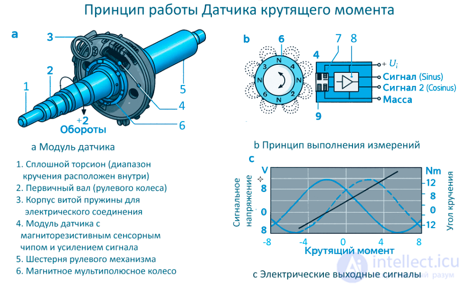
Figure Principle of operation of the torque sensor
a Sensor module
b Principle of taking measurements
c Electrical output signals
The magnetoresistive sensor used sends two signals within the measurement range, which are represented by the torsion bar's twist angle as sine and cosine signals. The calculation of the twist angle and, correspondingly, the torque is performed in the control unit using the arctangent function.
Since strict agreement between both signals is always ensured within the designated measurement range, any deviation from this agreement is recognized as a sensor malfunction, and the necessary measures are taken to replace it.
To ensure electrical contact of the sensor across a twist range of ± 2 turns of the steering wheel, angular springs with the required number of contacts are used. The angular springs supply the operating voltage and transmit the measurement parameters.
Static (reaction)
Measure the moment of force on stationary parts of a structure. Used in brake test stands, in testing engines and gearboxes.
Dynamic (rotating)
Mounted directly on the rotating shaft and operate in real time. These sensors are more often used in industrial and transport installations.
By type of transducer:
strain-gauge,
inductive,
optical,
magnetostrictive,
piezoelectric.
By measurement range:
low-torque (up to 1 N·m),
medium (up to 10³ N·m),
high-torque (up to 10⁶ N·m).
Torque sensors are widely used in various fields of engineering and science:
Automotive industry — measuring engine power, monitoring transmission load, assessing efficiency.
Industrial equipment — monitoring the condition of pumps, compressors, turbines, shafts, gearboxes.
Energy sector — monitoring the operation of generators and turbines.
Test stands — evaluating the characteristics of engines, drives and materials.
Robotics and automation — feedback for drive control.
Aerospace and shipbuilding industry — analysis of the dynamics and reliability of drive systems.
Torque sensors — are an essential tool for monitoring and analyzing rotational processes. They allow not only precise measurement of load, but also prevention of emergency situations, improved efficiency of mechanisms and reliability of systems.
Modern technologies make these sensors increasingly compact, precise and resistant to external influences, opening broad prospects for their use in the intelligent and automated systems of the future.

Comments