
Lecture
Particle detector, elementary particle detector, ionizing radiation detector in experimental particle physics — a device designed to detect and measure the parameters of high-energy atomic and subatomic particles, such as cosmic rays or particles produced in nuclear decays or in accelerators.
Obsolete
Detectors for radiation protection
Detectors for nuclear physics and particle physics
Recalling my experience with my own scintillation radiometer, I immediately said: BGO is hardly going to work here. The detector from the Atom Fast 8850 reliably starts "seeing" gamma quanta from 30 keV, while BGO has a scintillation efficiency about ten times worse. Add to that the light collection efficiency, which drops several-fold because of the large cross-sectional size of the puck relative to the detector, the enormous refractive index of BGO, and a detector build thrown together any old how, and we end up with a threshold around 0.5-0.6 MeV. It can be brought down to 150-200 keV with enough effort, but no further. Go find caesium iodide, I said to myself. Meanwhile I took the assembly apart, wiped the SiPM clean of petroleum jelly, soldered the MGTF wires to its contact pads a bit more neatly, and put it away somewhere safe...
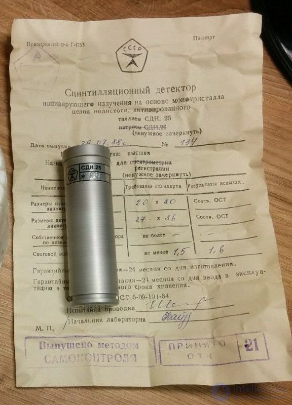
And a suitable CsI(Tl) crystal turned up, and in a geometry that happened to suit the SiPM very well. A "rod" 20 mm in diameter and 80 mm long, in a fairly standard aluminum housing with a window. Type SDN.25.20.80, "For detection". It turned up, admittedly, on "Avito", from a Ukrainian seller well known in narrow circles. Ten days later the scintillator was lying on my desk. The crystal, it must be said, didn't inspire much confidence: inside there was a layer of inclusions in the form of several black dots and a slight haze, and the window had pulled away from the crystal slightly at the edges. But at least it was intact, not cloudy, not yellowed, and there wasn't another one to be had anyway. We'll work with it.
An explanation is needed here as to why CsI(Tl) specifically, rather than its "older sibling" NaI(Tl). The point is that the latter is very sensitive to temperature swings and even light knocks, which cause it to crack. CsI is a material with a certain degree of plasticity, and under small mechanical loads it deforms rather than cracking. CsI(Tl) can also be "stripped" and repackaged without a dry glovebox with an inert atmosphere, whereas NaI(Tl) is so hygroscopic that it fogs over with dew and starts to run within a couple of minutes in open air. In our case there was no need for repackaging — the detector housing was quite sound and hermetically sealed, and I wouldn't vouch for the seal of a homemade container.
To start with, I decided to quickly press the SiPM against the crystal without any optical grease at all between it and the window — so as not to get it dirty for nothing. I taped it up with aluminum tape and black electrical tape to block outside light, connected it to a lab power supply through a 2.2 kΩ load resistor, and hooked an oscilloscope probe up to it... Well, not much to write home about. Sure, it's night and day compared with BGO, but the signal from Am-241 (59 keV) was about 8-10 mV at 29.5 V. And triggering off these pulses was very difficult: the noise pulses caused by dark photoelectrons were only slightly smaller than the useful signal.
Well then, let's first try doing it properly. At the same time we'll assess how much all these tricks actually matter.
Here we should start with the fact that the silicon photomultiplier itself is tiny compared to its vacuum counterpart. Its input window measures only 6x6 mm. Even our modest crystal has an output window area 8.7 times larger. A PMT is usually chosen with a photocathode diameter matching or nearly matching the scintillator diameter, since that's the case where light collection is most efficient and, which is especially important for gamma spectrometry, independent of where the light source (the scintillation flash) is located in space. In our case we would have had to put together a mosaic of at least four silicon PMTs, which didn't fit the budget given that we'd already had to buy the crystal (yes — we scientists sometimes have to buy things for our work out of our own pocket). We didn't need spectrometry either, and all we could do was hope that the light collected would be enough.
How can we optimize light collection in our case? If we don't unpack the crystal, our options are limited. And we'll make use of them.
What are these options? First, we need to eliminate the air gap between the crystal and the PMT. How much radiation do you think is lost because of it? It would seem like not much. The reflection coefficient at a glass-air boundary is ~4%, so you might expect us to lose only 8% of the light. But that would only be true if all the radiation hit the photocathode perpendicularly. That's not the case: light leaves the scintillator at all angles. And with the gap present, part of the light simply never leaves the crystal because of total internal reflection, while the radiation inside the "exit cone" is also partially reflected back into the crystal, and the larger the angle, the more strongly so.
To eliminate the air gap, the crystal and the photodetector are coupled using a transparent optical grease or adhesive whose refractive index is as close as possible to the refractive indices of the crystal window and the PMT window. Transparent petroleum jelly or silicone oil, or vinylin, can be used as the grease. There are also special optical contact greases, like those made by Alpha Spectra Inc and Saint Gobain (BC-631). Transparent silicone and epoxy compounds can be used for bonding. OCA — a sheet optical adhesive like double-sided tape, intended for bonding sensors to smartphone displays — can also be used successfully. This material is sold in every parts shop for phone repairs, and costs a few tens of rubles for a piece cut to the shape of a display.
The second thing to do is to close off every path by which light can leak out of the crystal. And the worst thing you can do here is give in to the temptation to take the easy route and just tape the window over with aluminum tape.
The thing is, bare aluminum only reflects 85-88% of light. The reflectivity of aluminum tape on the adhesive side is even lower, no more than 60-70%. Given that the light will be reflected back and forth inside the crystal several times before reaching the photodetector, these are very bad numbers. There are a number of materials with a very high diffuse reflection coefficient, over 95% — multilayer plastic films, Tyvek synthetic paper, and others. Nevertheless, the most accessible and quite effective reflector is ordinary white plumber's PTFE tape in several (4-6) layers, covered on top with aluminum foil, which gives a reflection coefficient of about 95%. SensL recommends exactly this for building scintillation detectors based on SiPMs. The "refined" equivalent made by Saint Gobain Crystals is called BC-642 Teflon Tape.
A light guide cone ("fokon" in the Russian jargon) is short for "focusing cone". The idea is that light falls on a conical or parabolic reflector that concentrates the light from a large input area onto a small output area. And this solution is indeed often used in scintillation detectors, to couple a crystal to a smaller-diameter PMT. But how well this solution actually works is quite debatable.
The thing is, the larger the ratio of the cone's input area to its output area, the narrower the cone of angles from which it collects light. Light falling at an angle greater than the critical angle is reflected back. And a scintillator emits light in all directions, so by limiting the angle over which light is collected, we lose part of it — there's no cheating nature here. The article shows that light-cone coupling gives nothing, either for light collection efficiency or for spectral resolution, at a crystal-to-SiPM-array size ratio similar to ours (a 2" diameter crystal and a 2x2 array of MicroFC 60035).
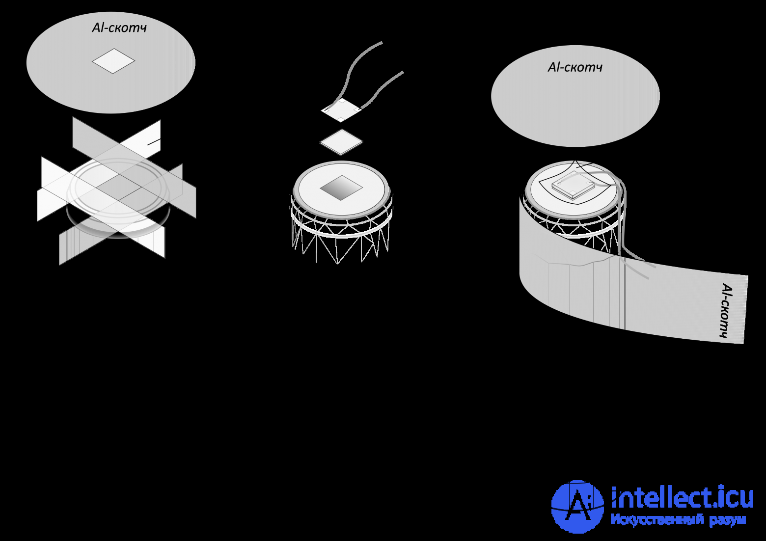
Since our crystal sits in a standard container with a quartz window at the end face, we don't need to worry about a light-reflecting coating over the whole crystal. It only needs to cover the end face, leaving a square window in the coating sized for the SiPM, i.e. 7x7 mm. The rest of the window area needs to be covered with strips of PTFE tape in 5-6 layers. Then cut a circle about 50 mm in diameter out of aluminum tape, cut an identical square hole in its center with a hobby knife, and stick it on top of the PTFE tape so the holes line up. Now carefully fold its edges over onto the cylindrical surface of the housing, smoothing and flattening the folds as thoroughly as possible, since light can get in through them.
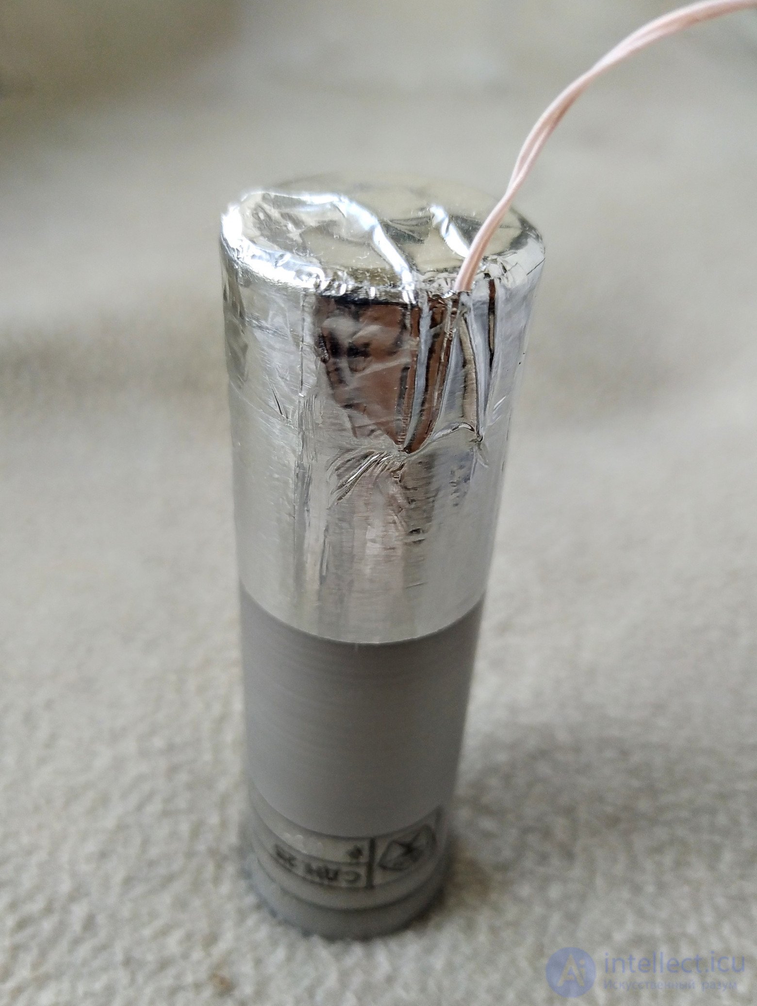
Into the square left free of PTFE tape and foil, we glue the SiPM using a square cut to its size out of OCA film. On top of it we stick a piece of Kapton film, so as not to short the silicon PMT's leads with the foil, and then cover it on top with a circle of aluminum tape to keep light out, routing the wires from the SiPM along the cylindrical surface of the crystal and wrapping the side surface with a strip of aluminum tape, hiding beneath it the unsightly folds that might let light through. However, the first power-up showed that this wasn't enough, and the detector only works properly if it's shielded from light. So I covered the assembly with one more layer of self-adhesive foil and routed the wires under it in a loop. In its final form the detector looks like this.
The result was not long in coming: the amplitude of the signal from the americium source more than doubled, reaching 20 mV, which lets it be reliably picked out against the dark noise background. That's how much light can be lost just because a couple of square centimeters around the SiPM are covered by an imperfect reflector, and because of the air-filled gap between it and the scintillator.
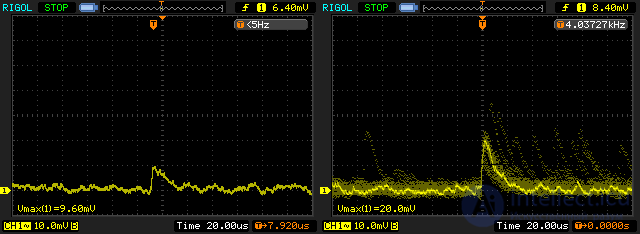
Pulses from americium with the detector built any old how (left) and after refinement (right)
Tellingly, the signal level doesn't change noticeably as the americium source is moved along the crystal. This shows that even with such a suboptimal coupling between the crystal and the PMT, light collection remains relatively uniform.
Recalling my experience with my own scintillation radiometer, I immediately said: BGO is hardly going to work here. The detector from the Atom Fast 8850 reliably starts "seeing" gamma quanta from 30 keV, while BGO has a scintillation efficiency about ten times worse. Add to that the light collection efficiency, which drops several-fold because of the large cross-sectional size of the puck relative to the detector, the enormous refractive index of BGO, and a detector build thrown together any old how, and we end up with a threshold around 0.5-0.6 MeV. It can be brought down to 150-200 keV with enough effort, but no further. Go find caesium iodide, I said to myself. Meanwhile I took the assembly apart, wiped the SiPM clean of petroleum jelly, soldered the MGTF wires to its contact pads a bit more neatly, and put it away somewhere safe...
And a suitable CsI(Tl) crystal turned up, and in a geometry that happened to suit the SiPM very well. A "rod" 20 mm in diameter and 80 mm long, in a fairly standard aluminum housing with a window. Type SDN.25.20.80, "For detection". It turned up, admittedly, on "Avito", from a Ukrainian seller well known in narrow circles. Ten days later the scintillator was lying on my desk. The crystal, it must be said, didn't inspire much confidence: inside there was a layer of inclusions in the form of several black dots and a slight haze, and the window had pulled away from the crystal slightly at the edges. But at least it was intact, not cloudy, not yellowed, and there wasn't another one to be had anyway. We'll work with it.
An explanation is needed here as to why CsI(Tl) specifically, rather than its "older sibling" NaI(Tl). The point is that the latter is very sensitive to temperature swings and even light knocks, which cause it to crack. CsI is a material with a certain degree of plasticity, and under small mechanical loads it deforms rather than cracking. CsI(Tl) can also be "stripped" and repackaged without a dry glovebox with an inert atmosphere, whereas NaI(Tl) is so hygroscopic that it fogs over with dew and starts to run within a couple of minutes in open air. In our case there was no need for repackaging — the detector housing was quite sound and hermetically sealed, and I wouldn't vouch for the seal of a homemade container.
To start with, I decided to quickly press the SiPM against the crystal without any optical grease at all between it and the window — so as not to get it dirty for nothing. I taped it up with aluminum tape and black electrical tape to block outside light, connected it to a lab power supply through a 2.2 kΩ load resistor, and hooked an oscilloscope probe up to it... Well, not much to write home about. Sure, it's night and day compared with BGO, but the signal from Am-241 (59 keV) was about 8-10 mV at 29.5 V. And triggering off these pulses was very difficult: the noise pulses caused by dark photoelectrons were only slightly smaller than the useful signal.
Well then, let's first try doing it properly. At the same time we'll assess how much all these tricks actually matter.
Here we should start with the fact that the silicon photomultiplier itself is tiny compared to its vacuum counterpart. Its input window measures only 6x6 mm. Even our modest crystal has an output window area 8.7 times larger. A PMT is usually chosen with a photocathode diameter matching or nearly matching the scintillator diameter, since that's the case where light collection is most efficient and, which is especially important for gamma spectrometry, independent of where the light source (the scintillation flash) is located in space. In our case we would have had to put together a mosaic of at least four silicon PMTs, which didn't fit the budget given that we'd already had to buy the crystal (yes — we scientists sometimes have to buy things for our work out of our own pocket). We didn't need spectrometry either, and all we could do was hope that the light collected would be enough.
How can we optimize light collection in our case? If we don't unpack the crystal, our options are limited. And we'll make use of them.
What are these options? First, we need to eliminate the air gap between the crystal and the PMT. How much radiation do you think is lost because of it? It would seem like not much. The reflection coefficient at a glass-air boundary is ~4%, so you might expect us to lose only 8% of the light. But that would only be true if all the radiation hit the photocathode perpendicularly. That's not the case: light leaves the scintillator at all angles. And with the gap present, part of the light simply never leaves the crystal because of total internal reflection, while the radiation inside the "exit cone" is also partially reflected back into the crystal, and the larger the angle, the more strongly so.
To eliminate the air gap, the crystal and the photodetector are coupled using a transparent optical grease or adhesive whose refractive index is as close as possible to the refractive indices of the crystal window and the PMT window. Transparent petroleum jelly or silicone oil, or vinylin, can be used as the grease. There are also special optical contact greases, like those made by Alpha Spectra Inc and Saint Gobain (BC-631). Transparent silicone and epoxy compounds can be used for bonding. OCA — a sheet optical adhesive like double-sided tape, intended for bonding sensors to smartphone displays — can also be used successfully. This material is sold in every parts shop for phone repairs, and costs a few tens of rubles for a piece cut to the shape of a display.
The second thing to do is to close off every path by which light can leak out of the crystal. And the worst thing you can do here is give in to the temptation to take the easy route and just tape the window over with aluminum tape.
The thing is, bare aluminum only reflects 85-88% of light. The reflectivity of aluminum tape on the adhesive side is even lower, no more than 60-70%. Given that the light will be reflected back and forth inside the crystal several times before reaching the photodetector, these are very bad numbers. There are a number of materials with a very high diffuse reflection coefficient, over 95% — multilayer plastic films, Tyvek synthetic paper, and others. Nevertheless, the most accessible and quite effective reflector is ordinary white plumber's PTFE tape in several (4-6) layers, covered on top with aluminum foil, which gives a reflection coefficient of about 95%. SensL recommends exactly this for building scintillation detectors based on SiPMs. The "refined" equivalent made by Saint Gobain Crystals is called BC-642 Teflon Tape.
A light guide cone ("fokon" in the Russian jargon) is short for "focusing cone". The idea is that light falls on a conical or parabolic reflector that concentrates the light from a large input area onto a small output area. And this solution is indeed often used in scintillation detectors, to couple a crystal to a smaller-diameter PMT. But how well this solution actually works is quite debatable.
The thing is, the larger the ratio of the cone's input area to its output area, the narrower the cone of angles from which it collects light. Light falling at an angle greater than the critical angle is reflected back. And a scintillator emits light in all directions, so by limiting the angle over which light is collected, we lose part of it — there's no cheating nature here. The article shows that light-cone coupling gives nothing, either for light collection efficiency or for spectral resolution, at a crystal-to-SiPM-array size ratio similar to ours (a 2" diameter crystal and a 2x2 array of MicroFC 60035).
Since our crystal sits in a standard container with a quartz window at the end face, we don't need to worry about a light-reflecting coating over the whole crystal. It only needs to cover the end face, leaving a square window in the coating sized for the SiPM, i.e. 7x7 mm. The rest of the window area needs to be covered with strips of PTFE tape in 5-6 layers. Then cut a circle about 50 mm in diameter out of aluminum tape, cut an identical square hole in its center with a hobby knife, and stick it on top of the PTFE tape so the holes line up. Now carefully fold its edges over onto the cylindrical surface of the housing, smoothing and flattening the folds as thoroughly as possible, since light can get in through them.
Into the square left free of PTFE tape and foil, we glue the SiPM using a square cut to its size out of OCA film. On top of it we stick a piece of Kapton film, so as not to short the silicon PMT's leads with the foil, and then cover it on top with a circle of aluminum tape to keep light out, routing the wires from the SiPM along the cylindrical surface of the crystal and wrapping the side surface with a strip of aluminum tape, hiding beneath it the unsightly folds that might let light through. However, the first power-up showed that this wasn't enough, and the detector only works properly if it's shielded from light. So I covered the assembly with one more layer of self-adhesive foil and routed the wires under it in a loop. In its final form the detector looks like this.
The result was not long in coming: the signal amplitude from the americium source increased more than twofold, reaching 20 mV, which makes it possible to confidently distinguish it against the dark-noise background. That is how much light can be lost simply because a couple of square centimetres around the SiPM are covered by a non-ideal reflector, and because of the air-filled gap between it and the scintillator.
Pulses from americium recorded by a detector assembled carelessly (left) and after refinement (right)
It is telling that the signal level does not change noticeably when the americium source is moved along the crystal. This indicates that even with such a suboptimal coupling of the crystal and the photomultiplier, light collection remains relatively uniform.
In particle physics, the concept of a “detector” refers not only to various types of sensors for registering particles, but also to large installations built on their basis, which include the infrastructure for keeping them operational (cryogenic systems, air-conditioning systems, power supply systems), electronics for reading out and performing primary processing of the data, and auxiliary systems (e.g. superconducting solenoids for creating a magnetic field inside the installation). As a rule, such installations are now built by large international collaborations.
Since building a large installation requires significant financial expenditure and human effort, in most cases it is used not for a single specific task but for a whole range of different measurements. The main requirements imposed on a modern detector for accelerator experiments are:
Specific tasks may require additional requirements, for example, for experiments measuring CP violation in the B-meson system, coordinate resolution in the beam interaction region plays an important role.
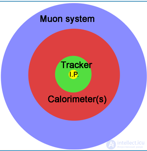
Schematic representation of a multilayer general-purpose detector for a colliding-beam accelerator.
The need to satisfy these conditions leads to the scheme, typical today, of a general-purpose multilayer detector. In the English-language literature it is customary to compare such a scheme to an onion (onion-like structure). Moving from the centre (the beam interaction region) toward the periphery, a typical detector for a colliding-beam accelerator consists of the following systems:
The tracking system is designed to register the trajectory of a charged particle as it passes through: the coordinates of the interaction region, the emission angles. In most detectors the tracking system is placed in a magnetic field, which causes the trajectories of the charged particles to curve and makes it possible to determine their momentum and the sign of their charge.
The tracking system is usually built on the basis of gas ionization detectors or semiconductor silicon detectors.
The identification system makes it possible to separate different types of charged particles from one another. The operating principle of identification systems most often consists in measuring the particle's time of flight using one of three methods:
Together with the momentum measurement in the tracking system, this gives information about the mass, and consequently about the type, of the particle.
The calorimeter is designed to measure the energy of particles by their complete absorption. This is the only way of registering photons (since they are not charged and, consequently, leave no tracks in the tracking system). Photons and electrons produce an electromagnetic shower in the medium and are thus completely absorbed. The released energy can be measured either from the magnitude of the scintillation light flash (scintillation calorimeters) or by counting the particles of the shower (sampling calorimeters).
The muon system can be classified as part of the identification system, but technically it is implemented separately, in the outer part of the detector. Most often it is built into the iron that closes the magnetic flux of the tracking system's solenoid. The muon system makes it possible to separate muons by their ability to travel long distances in matter without being absorbed (this is a consequence of the fact that the muon does not undergo nuclear interaction).
The overwhelming majority of “pocket-format” dosimeters and radiometers are instruments based on a Geiger counter. This type of detector has its merits, the main ones being simplicity and low cost, but also a number of drawbacks. First and foremost among these is a very low efficiency of registering gamma quanta and a complete lack of information about their energy. A Geiger counter registers only one gamma quantum out of several hundred, whereas a scintillation detector gives almost 100% efficiency at low energies. As a result, under natural background radiation and with detectors of the same size, when a Geiger counter gives only 10-15 pulses per minute, a scintillator gives the same number of pulses, but per second. Thus, to obtain even a rough idea of the dose rate, we must spend at least a minute accumulating pulses with a Geiger counter, while with a scintillator we can obtain information about the radiation situation every second. So a scintillation detector primarily gives us a fast response to weak sources of radioactivity.
Besides this, a scintillation detector has the property of proportionality. The higher the particle's energy, the larger the pulse amplitude at the detector's output. What is this needed for? First, this way we get information about what is the source of the radiation. Each radioactive isotope has its own characteristic gamma-radiation energy (or set of energies). The method of gamma spectrometry is based on this. In this device, the value of the average absorbed energy per quantum will be displayed on the screen (not implemented yet).
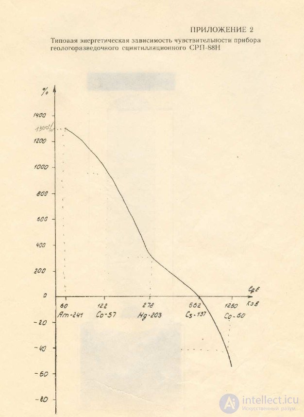
Second, if we simply count pulses without taking energy into account, we get an unpleasant thing called “energy dependence” (drift with hardness). Suppose we calibrated our radiometer against caesium-137. And then found ourselves in a place contaminated with americium-241. The quantum energy of caesium-137 is 667 keV, that of americium is 59 keV, that is, more than an order of magnitude less. This means that with the same number of particles captured by the detector (and hence the same instrument readings), the absorbed dose will turn out to be more than an order of magnitude smaller. That is, the measurements will be erroneous. And in order for the radiometer to measure the dose correctly at different energies (that is, to be a dosimeter), it is necessary to take into account the energy of each registered quantum.
Portable scintillation radiometer-dosimeters have existed on the market for a long time. But for the most part these are very expensive instruments for professional use. I know of only one device aimed at home and amateur use — this is the Atom Fast, made by the design bureau “Radar”. The rest — devices from the company “Polimaster”, and a number of foreign companies — are very expensive.
In this device I wanted to achieve the following:
The result was the device described here. It is not yet finished, there is still quite a lot of work to do, especially on the software.
The radiometer operates in one of two modes: search mode and measurement mode. In search mode, the instrument's readings are updated every second, and besides the digital readout they are also displayed as a graph. In search mode no attention is paid to errors; in this mode the instrument is, first and foremost, an indicator. The screen displays: the current dose rate, the count-rate value in counts per second (CPS), as well as the dose rate averaged over the last minute and the integral dose accumulated since the instrument was switched on or since the last reset. In measurement mode, by contrast, the measurement time is set by the operator (by pressing the “Enter” button to start, and then to end the measurement), and the screen displays, together with the measured value, the calculated error, while its “footer” shows a mini-log of the last several measurements. In addition, in measurement mode a first attempt has been made to take the energy of the quanta into account and compensate for “energy dependence”. Measurement mode is deep under construction, and it is not yet present in the firmware version given here.
Regardless of the mode, the once-per-second measurement cycle continues, with the results being saved to RAM. In particular, thanks to this, when switching to search mode the graph displays readings that were taken while the instrument was in measurement mode, as well as during visits to the menu, etc. The threshold-exceedance alarm also works regardless of the mode.
The alarm has three thresholds. The traditional first and second are set through the menu at the operator's discretion, and when they are triggered, based on the results of the next one-second counting cycle, an audible signal sounds. Besides these there is also an adaptive threshold. It is set automatically based on the average level over the last minute, being set at one, two or three sigmas (selectable in the settings) above it. If the alarm was triggered by this threshold in a given cycle, the value from the previous cycle is used for the next cycle, thanks to which, with a slow but steady rise in radiation, a stable triggering of the alarm is achieved. In the future a log of alarm triggers will be implemented, but it does not exist yet.
Also not yet implemented is saving measurement results to a MicroSD card, a slot for which is mounted on the radiometer's board. It also provides for connecting a GPS module, the use of which is likewise a matter for the future.
Switching between modes and quickly changing some settings is done via “hotkeys”, the rest of the operations are done via the menu. Entering the menu, as already mentioned, does not stop the measurement process.
The radiometer is mounted in a standard Gainta G1389G enclosure from “Chip and Dip” measuring 122x77x25 mm. On its top panel is a colour LCD display measuring 3.5" with a resolution of 480x320 pixels. An HMI module, the Nextion NX4832T035, is used as the display; it differs from ordinary displays in having its own microcontroller, which contains a ready-made program for displaying interface elements, and all we need to do is send it commands to display them, remove them or change them — for example, to change one figure or another, draw the next point on the graph, or change the colour of some label. Below the display is a keypad of five buttons. Below the keypad, space has been left for a GNSS receiver. On the top edge is the scintillation detector.
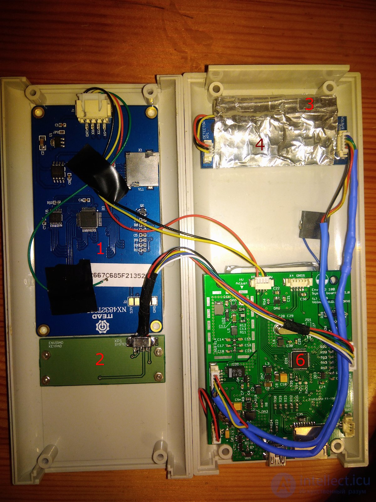
The red numbers denote: 1 — the display module, 2 — the keypad, 3 — the detector, 4 — the analog board, 6 — the system board.
The device's electronic circuitry (not counting the display, the navigation receiver, and the keypad) is assembled on two printed circuit boards. The first holds the analog part of the device, the second holds everything else: the microcontroller with its supporting circuitry, the power supply and switching circuits, the battery charging circuit, and the high-voltage source for the detector.
The detector used in the radiometer is a thallium-activated caesium iodide scintillation crystal. This crystal has the property of radioluminescence – charged particles and high-energy photons (in the X-ray and gamma range) excite a glow in it, with the light being emitted as a short flash, about a microsecond long – a scintillation. This flash is too weak to be seen with the eye or detected by ordinary means. Photocells, photodiodes and photoresistors are too insensitive for this. To give a sense of the scale of the problem, let me cite the following figures.
A gamma quantum with an energy of 1 MeV, having been completely absorbed in a CsI(Tl) crystal, produces approximately 40,000 photons of green light. Suppose we try to catch this light with a photodiode. Let us assume all of them hit the photodiode (in reality this is unrealistic, and it would be good if even half of them hit it). And let us further assume that our photodiode is ideal, with a quantum yield of 100%. This means that each of the photons will create one electron-hole pair in the photodiode's structure. And per pulse we will get 40,000 photoelectrons. And this pulse lasts, as we know, 1 μs. This means that per second we will have 4∙1010 photoelectrons. The charge of an electron is 1.6∙10-19 C, and the charge of 4∙1010 photoelectrons is 6.4∙10-9 C, that is, the current that the scintillation flash will induce in our photodiode is only a few nanoamperes! And if we recall that not all the photons hit the photodiode, and its quantum yield is not 100%… Moreover, a megaelectronvolt is the energy of fairly hard gamma radiation, and we would like to see significantly lower energies as well. In short, photodiodes are practically unsuitable here. Or rather, they are suitable — but with very great difficulty.
Photomultiplier tubes were usually (and still are) used to capture such weak light pulses. In them, each photoelectron knocked out of the photocathode is multiplied by a system of dynodes, giving a gain of millions of times, and the current pulse at its anode is already not nano- but milliamperes, and registering such a pulse is no longer difficult. But a PMT is a fragile glass bulb of considerable size, requiring a kilovolt power supply that must also be highly stable. In short, it is hard to imagine it in a pocket-sized instrument.
Fortunately, semiconductor photodetectors capable of rivalling PMTs in sensitivity have now appeared. Who said – avalanche photodiodes? Yes, that's almost right. Except avalanche diodes, although they have internal amplification of the photocurrent through avalanche multiplication of carriers, have a number of technological problems that prevent making a sensitive area even a few millimetres in diameter. In addition, the avalanche gain of a classical avalanche diode, without elaborate tricks, is only 10-200, which is a pittance compared with the millionfold gain characteristic of a PMT. All these drawbacks of the avalanche photodiode have been eliminated in the Si-PMTs, or SiPMs, that have recently appeared on the market. They are essentially an array of many avalanche photodiodes operating in Geiger mode, in which a single photon can trigger the development of an avalanche breakdown. This mode is similar to the operation of a Geiger counter. Each of the cells has its own quenching circuit, thanks to which the avalanche breakdown stops immediately and the cell becomes ready again to register a new photon. All the cells (with their quenching circuits) are connected in parallel on the Si-PMT chip, and the current pulses flowing through them are summed, so that the average current turns out to be proportional to the illumination of the crystal. And using such a silicon PMT is very simple – it is enough to apply a reverse bias to it – about 28-29 V through a resistor of several kilo-ohms, from which the signal is taken. Nothing else is needed – neither a kilovolt power supply, nor a divider for dynodes. And the Si-PMT itself is a small square of silicon measuring 3x3 or 6x6 mm. Incidentally, if the reverse bias is removed from it or reduced to a few volts, it works like an ordinary photodiode.

So, our detector uses an Si-PMT and a CsI(Tl) crystal, with a layer of optical grease applied between them to eliminate the air gap between the crystal and the photodetector's window. And on top, the crystal and the Si-PMT are covered with multiple layers of thin PTFE film, known as PTFE (FUM) tape. Such a coating has a very high coefficient of diffuse reflection. On top, the detector is covered with aluminium tape, providing protection from outside light and sealing – a caesium iodide crystal dissolves extremely easily in water, and the ingress of even the slightest traces of moisture into the detector would lead to its destruction. Fortunately, unlike its “relative” — sodium iodide, CsI is practically non-hygroscopic – that is, it does not draw moisture from the air. Sodium iodide crystals have to be processed only in an atmosphere of completely dry inert gas and placed in containers as highly sealed as if an ultra-high vacuum needed to be created inside them, while in ordinary air they simply deliquesce before your eyes. Conversely, caesium iodide in the form of single crystals can be safely worked in air (for example, sawn with an ordinary hacksaw and sanded with sandpaper), avoiding only the ingress of traces of liquid water and bearing in mind that the crystal contains extremely toxic thallium. However, because of the small quantity of it, the acute (but not chronic!) toxicity will be determined by the iodine, not by the thallium.
I will not give advice on making a detector yourself, since I have not done so (the finished detector was kindly provided to me by its developer and manufacturer KBRadar in exchange for some artefacts of value to electronics enthusiasts); I will only give its parameters. They are as follows: crystal dimensions 8x8x50 mm, with an Si-PMT, the MicroFC 30035 from the Irish company SensL (now a division of On Semi), used as the photodetector. And a variety of tips on manufacturing can be found online. With a somewhat larger size, you can take a standard CsI(Tl) or NaI(Tl) crystal in its “native” small-sized packaging (10x40, 18x30 mm, etc.). However, the larger the output window, the worse a photodetector measuring 3x3 mm will perform, so I strongly recommend that, for an output window diameter greater than 10 mm, you take the larger (and considerably more expensive) MicroFC 60035. Incidentally, the equivalents of these photodetectors from Broadcom are strongly not recommended for use. Besides having a package (WLCSP-16) that is thoroughly unsuitable for home soldering, they also have an almost order-of-magnitude higher noise level.
CsI(Tl) crystals were processed as follows. On all samples the side surface was ground to a matte finish. The end faces were first ground on fine sandpaper and then on silk cloth. Cerium oxide dissolved in ethyl alcohol was used for finer polishing. Polishing was continued until glass-like transparency was reached. If the crystal needed to be cut down to a greater thickness, it was simply sawn with a wire moistened in water. It was then processed in the same sequence as above.
(Gorbunov V.I., Kuleshov V.K. On choosing the optimal size of scintillators for flaw detection in products // Proc. Tomsk Polytechnic Institute. 1965. Vol.138. P.42-48.)
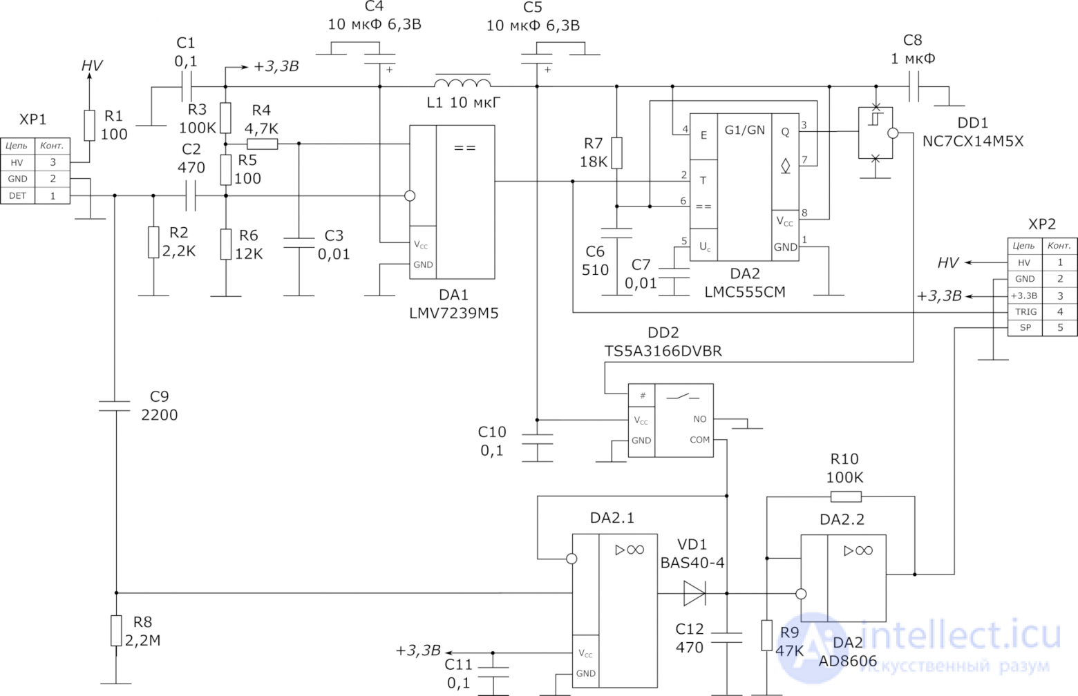
Its circuit is shown in the figure above. It consists of the following main blocks:
The detector connects to input connector XP1. The Si-PMT cathode – to pin 3 (HV), the anode – to pin 1 (DET), and the detector's metal shield – its wrapping of aluminium tape – connects to pin 2 (GND).
The input circuit consists of the detector load resistor R2 and the current-limiting resistor R1, which attempts to protect the detector in case of trouble such as an accidental application of too high a reverse-bias voltage, or the erroneous application of reverse-polarity voltage instead, or finally – incorrect connection of the detector itself. Together with the capacitance of the silicon PMT (about 900 pF), they shape voltage pulses with a rise time of about 1 µs and a fall time of about 15 µs. Before being fed to the comparator input, the signal passes through a 470 pF capacitor, which blocks DC and, together with the input resistance of the divider R3R5R6, shortens the pulse to 2-3 µs.
The comparator used is the LMV7239 chip, which combines low current consumption with fairly high speed (< 100 ns) at small differential input voltages. The voltage divider R3R5R6, together with the integrating circuit R4C3, forms a “floating” threshold voltage, making the comparator largely insensitive to the detector's dark current and to changes in its own input current with temperature. The comparator's sensitivity is adjusted by selecting the resistance R5 in a range of a few tens of ohms. A negative-polarity rectangular pulse is formed at the comparator's output. The trailing edge of this pulse may chatter slightly due to detector noise, but attempting to get rid of this chatter by introducing hysteresis led to reduced sensitivity and, on the whole, worse results. This pulse gates the peak detector and is fed to the digital section, where it generates a microcontroller interrupt.
A one-shot built around the integrated timer DA2 (LMC555CM, essentially an ordinary 555 timer, only in CMOS design) generates a pulse (of positive polarity) with a duration of 10 µs (set by the timing network R7C6) on the leading edge of the pulse at the comparator output. This pulse is inverted by DD1 (a single inverter of the TinyLogic series in an SOT23-5 package) and fed to switch DD2, which shorts out capacitor C12 of the peak detector in the absence of input pulses. When a pulse arrives, the short is removed for the stated 10 µs.
The peak detector is built on the classic non-inverting circuit. The drawbacks of this circuit are well known, but in this variant an interesting effect arises. The point is that while waiting for a pulse, the feedback loop of DA2.1 is open, and the op-amp, at the moment an input pulse arrives, must end up in an overload state, from which recovery takes considerable time, while the state of the amplifier before the pulse arrives is undefined altogether (which is the source of all the drawbacks of peak detectors of this kind). On the other hand, the voltage at the non-inverting input in the preceding moment is close to zero, and the capacitor is shorted, so the voltage at the inverting input is also zero. At the moment a pulse arrives, the op-amp's output at that instant finds itself in a short-circuit condition, and the protection circuits against this engage the op-amp via an internal feedback loop that limits the output current! Because of this, the amplifier's output stage is no longer in the limiting mode but is instead forced into the linear mode, out of which it then emerges easily and quickly. As a result, such a peak detector operates noticeably faster than if it were reset at the end of the pulse by briefly shorting capacitor C12.
The condition for this circuit to function normally is the absence of a DC component in the detector's signal, which would immediately drive the op-amp into overload, and a significant current would then flow through the diode and the shorted capacitor (limited, however, by the aforementioned built-in feedback loop, so nothing burns out). That is why a coupling capacitor C9 is also placed at the input here. Resistor R8 provides for the discharge of this capacitor if it happens to become charged (otherwise it would have nowhere to discharge to – the input resistance of DA2 approaches a teraohm). Without it, amusing quirks are observed, where the circuit works normally for a while, then suddenly stops, and resumes working again after some time.
How well the peak detector works usually depends directly on the parameters of its capacitor. A non-polar film is usually used, often PTFE, since low absorption with low leakage is required. Here the requirements on it are relaxed by the fact that it is constantly shorted in the absence of a pulse (which suppresses the effect of absorption) and by the fact that the charge storage time is only 10 µs, so a good-quality ceramic capacitor of the 1206 package size, necessarily with an NP0 dielectric, is quite applicable here.
On the second op-amp of chip DA2 a buffer with high input resistance is built, allowing the voltage to be taken off the peak detector's capacitor without discharging it, with its gain set by resistors R9 and R10.
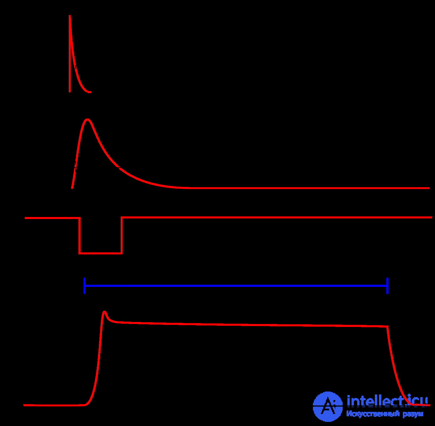
When a pulse arrives from the detector at the input, this circuit forms a zero-logic-level pulse at the TRIG output with a duration of 2-4 µs and a near-rectangular pulse with a duration of 10 µs at the SP output, with a level proportional to the amplitude of the pulse received from the detector. For most of these 10 µs the voltage level remains constant, which allows it to be measured several times with the microcontroller's built-in ADC, and the TRIG signal must, before that, “wake up” the MCU and launch the interrupt handler, in which this measurement (together with pulse counting) is implemented.
For operation the circuit requires two supply voltages: 3.3 – 5 V for the circuit's operation and a “high” voltage of 28-29 V for biasing the detector. The current consumption is about 2.5 mA. On the “high-voltage” line the current consumption depends on the detector's load and, at background radiation levels, amounts to a few microamps. It is assembled on a printed-circuit board measuring 64x22 mm using surface-mount technology.
After assembly everything should start working right away, however when testing it one must remember that the TRIG output is a very high-speed comparator output and is capable of generating powerful interference. Because of this, when connecting it (for example, to an oscilloscope) with a long unshielded lead, everything will start oscillating. For this same reason, on the board version I designed, pickup from this signal onto the TRIG signal is observed in the form of high-frequency “ringing”. When assembling the finished instrument, the board should be connected to the system board with a harness of minimum length, in which the TRIG and SP lines are separately shielded, for example using adhesive nickel fabric grounded to the common wire.
It contains the following main blocks:
The power supply circuit (I apologize in advance for not bringing the further diagrams up to standard and taking them directly from Eagle) is shown in the figure below.
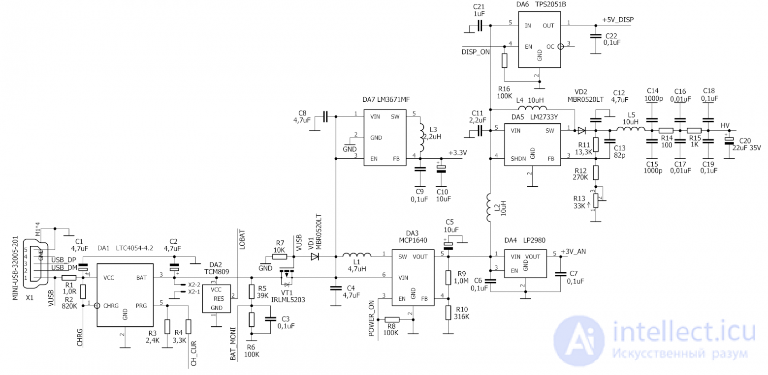
The instrument is powered from a single-cell lithium-ion battery connected to connector X1. I used a “Robiton” lithium-polymer battery rated at 2.3 Ah; in principle, any smartphone-type battery of similar capacity will do. DA1 forms a charger for it, powered from the USB port. There is nothing special here, everything follows the datasheet for the LTC4054-4.2. The charging current can be increased from 350 to 700 mA by pulling the lower resistor R4 lead (as drawn) to the common wire via an MCU port. This is needed so as not to exceed the permissible 500 mA from the USB port while still allowing the battery to charge faster if the instrument is connected to a mains adapter. Via DA2 the MCU finds out that the battery has discharged and switches the instrument off, while the divider R5R6C3 allows the voltage across it to be measured (routed to one of the MCU's analogue inputs). The CHRG line from DA1 allows the MCU to monitor the charger's state using a clever algorithm: when there is no charge, it is at zero; during charging a one appears, one that is easily pulled down to zero; and when fully charged it stops being pulled down and remains a one even under a load of several kilohms. In place of DA1, besides the costly original LTC4054-4.2, its clone from ST — the STC4054 — can also be used. I warn against using Chinese LTC4054 chips from AliExpress: they either don't work at all, or work incorrectly, killing the battery and creating a risk of it exploding. It was precisely because of this that I gave up using the “popular” TP4056: the original has long been out of production and cannot be obtained, while the clones either lack pre-charging, or have a voltage spread of 4.2 V — almost a full volt, or have the thermal protection gutted… All in all, the only properly working sample of this chip I have is on a small lithium-charging board I once bought. A pity: it has simpler mode indication, a higher maximum charging current, and cooling via an SO-8 package with an exposed pad — better in every way than via the leads of an SOT-23-5.
The circuit VT1VD1R7 disconnects the load from the battery and switches it to power from the USB port when voltage appears on it, so as not to interfere with DA1 correctly maintaining the charge mode and detecting its completion.
Next come the converters for obtaining the required supply voltages. Chip DA3 steps up the battery voltage to 5 V, which powers the display, the step-up converter for obtaining 28 V for the detector, and, through a linear regulator, the analogue board. The MCU can turn off all these loads by setting the POWER_ON line to zero. The display is turned off separately, by switch DA6.
To obtain the high voltage, a step-up converter is built around DA5. The highest-voltage variant of the DC-DC converter, the LM2731, was chosen. Initially it was planned to use the much more efficient (in this circuit) Chinese MT3608, but it showed very low reliability at an output voltage of 28-29 V (indeed, according to the datasheet the maximum permissible output voltage for it is 28 V, so this is not surprising). When tuning this section of the circuit, keep in mind that if the lower arm of the divider (R12R13) breaks, the output voltage jumps to 50-60 V, blowing out capacitor C20, which is dangerous for the eyes (they explode quite impressively!). And if R11 is accidentally shorted, the FB input (pin 3 of DA5) burns out with a similar effect (plus the chip will need replacing). Because of this, close attention must be paid to the quality of the trimming resistor and to correct assembly. The output filter is needed to suppress ripple at the output of this converter. The converter is enclosed in a tin shield, soldered at its edges to the ground plane on the board.
Instead of DA3, as practice has shown, a switch similar to DA6 can be installed with a board revision (accordingly, the inductor and diode are not needed, nor are the two resistors R9 and R10). This makes the instrument somewhat more energy-efficient. In that case regulator DA4 should be set not to 3.3 V, but to 3.0 V, so that the analogue supply remains regulated across the whole range of battery discharge.
Converter DA7 operates all the time, including when the instrument is switched off, supplying the MCU with 3.3 V. At no load it consumes only a few tens of µA, so the switched-off instrument barely discharges the 2.3 Ah battery. Unfortunately, the STM32L151 has no separate supply input for the RTC, which is why this solution had to be adopted (otherwise the switching would have had to be made more complicated).
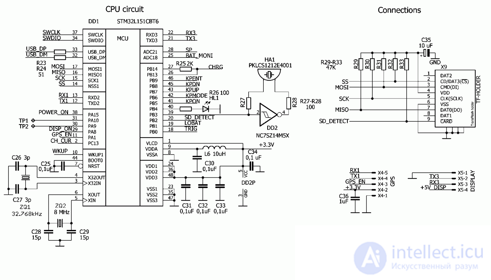
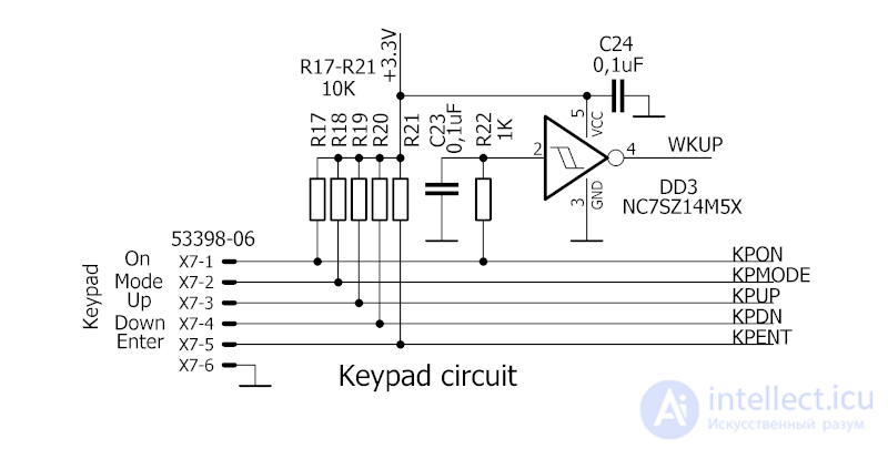
продолжение следует...
Часть 1 Particle Detectors: Elementary Particle Detectors, Ionizing Radiation Detectors, Scintillation Counters
Часть 2 Applied Uses - Particle Detectors: Elementary Particle Detectors, Ionizing Radiation

Comments