
Lecture
Let's look at miniature devices — the gyroscope and the accelerometer — which are built into many modern electronic devices: players, tablets, communicators, photo and video cameras. A synonym for the word “gyroscope” is “gyro sensor”, and a synonym for “accelerometer” is G-sensor. The gyroscope and accelerometer themselves are different things (some people confuse them), but they complement each other perfectly, working as a pair.
Accelerometer (G-sensor, acceleration sensor) — is a miniature device that, in scientific terms, measures the projection of apparent acceleration. In simpler terms, it determines the angle of tilt of the device relative to the surface of the Earth. Software that receives information about the tilt angle from the accelerometer rotates the image on the screen. For example, on a device with a G-sensor, switching to landscape screen orientation takes just a 90-degree turn of the device. The image on the screen rotates as if “by itself”, because the accelerometer is triggered.
As is known, the displacement of an object, its velocity and acceleration are interrelated quantities, since velocity and acceleration are derivatives of displacement. Using simple electrical circuits, the conversion of acceleration into velocity and velocity into displacement can be carried out with high precision. That is why accelerometers are today the primary vibration sensors: their output signal can easily undergo single or double integration to obtain either velocity or displacement.
However, the integration method is not suitable for low-frequency signals, where the error of signals with high noise is too large and unacceptable for measurements. Therefore, in the low frequency band (around 1 Hz), position sensors are usually used; for signals below 1 kHz, velocity sensors are most suitable; and in the high-frequency range, acceleration sensors are used.
Depending on the type of motion being measured, accelerometers are divided into angular and linear. Linear accelerometers consist of a magnet and an induction coil, whose output voltage is directly proportional to the velocity of the magnet. Since linear sensors can only measure acceleration within their own dimensions, they are often used to measure vibrations. In angular accelerometers, the magnet is located inside the induction coil, and the output signal is proportional to the velocity of the magnet's motion.
Gyroscope (gyro sensor) — is a device that serves to determine the orientation of a device in space, to track its movement. Software used together with a gyroscope is able to quickly react to the movement of a device in space and make appropriate decisions. For example, in laptops, a gyroscope allows a hard drive lock mode to be quickly enabled in the event of a fall or simply a sharp movement of the device. This is very useful, so it is desirable that the laptop/netbook you buy is equipped with a gyro sensor. However, in many. laptops, an accelerometer is also used for similar purposes.
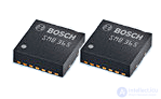
The capacitive method of converting measured displacement is the most accurate and reliable, which is why capacitive accelerometers have become widespread.
Gyroscopes, along with compasses, are widely used to solve navigation problems. The operating principle of gyroscopes is based on the Coriolis acceleration effect.
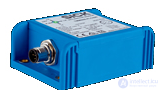
An inclinometer (from Latin inclino — to incline, and …meter) — is a device designed to measure the angle of tilt of various objects relative to the Earth's gravitational field. In addition to the tilt angle value itself, its direction — the azimuth — can also be measured. Industrial inclinometers provide contactless measurement of an object's tilt angle relative to the Earth's axis. Such inclinometers usually have a built-in accelerometer and gyroscope
Piezoelectric and strain gauge accelerometers are built on the basis of solid-state materials that have electrical sensitivity to mechanical action.
This type of acceleration sensor is widely used for vibration measurements, thanks to the accuracy of the data, reliability and simple design (fig. 1, a). The sensitivity of automotive accelerometers is about 20 mV/g; they are small in size and are produced in integrated form with thermal compensation. Their error is 0.5% at temperatures of -40...+110 °C.
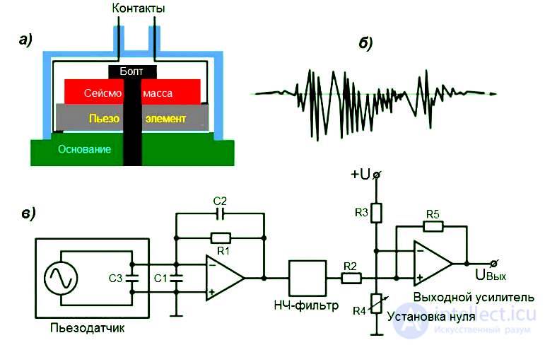
Fig. 1. acceleration sensors and accelerometers
a) Basic design of an accelerometer;
b) High-frequency signal of a piezoelectric sensor;
c) Amplifier-shaper circuit for processing the signal of a piezoelectric accelerometer
When the piezoelectric crystal is deformed (compressed), an electrical signal proportional to the acceleration appears on its faces. The operating frequency range is 5...100000 Hz. To process the signal from such piezoelectric sensors, an electronic amplifier-shaper is used (fig. 1, c). Automotive airbag accelerometers
These accelerometers are mechanical sensors of the inertial type. Such sensors are usually located no more than 40 cm from the expected point of impact. Usually 3...5 sensors are used.
The specific design of inertial sensors may differ among different safety system manufacturers, but they all operate on the same principle.
Under normal vehicle driving conditions, the output contacts of the accelerometer are open; they close when the sensor experiences negative acceleration in the range of 15...20 g, which corresponds to the vehicle hitting a solid obstacle at a speed of 15...30 km/h. There are several accelerometer designs used in safety systems.
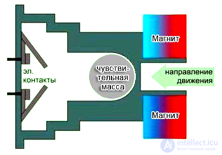
Fig. 2. Permanent magnet accelerometer
The most common mechanical accelerometers are permanent magnet accelerometers. This mechanical design (fig. 2) consists of a sensing mass (a metal ball), which is firmly held in the rear part of a small cylinder by a powerful permanent magnet.
The sensor's output electrical contacts are always open, and upon collision, the inertial force of the metal ball overcomes the magnet's attraction, the ball moves along the cylinder and closes the contacts, and the signal is sent to the ECU.
In such sensors, various design parameters of its elements, such as the mass of the ball, the magnet's attraction force, damping, etc., are matched to the dynamics of the specific vehicle in a crash. This takes into account the vehicle's weight, body design, and sensor locations.
In recent years, in mechanical engineering, including automotive engineering, integrated accelerometers based on semiconductor or piezoelectric strain gauges have become widely used, featuring small size, high reliability, and programmability. Such integrated sensors are placed as close as possible to the center of the cabin.
Their sensitivity to impact acceleration is higher than that of mechanical ones, due to the damping of the housing. One sensor is used for frontal impact with a range of ±50 g.
Side impact sensors may be used, piezoresistive or capacitive, with an error of less than 5% and a frequency range of 0...750 Hz.
Accelerometers are also used in active suspension to determine changes in wheel load; their operating range is ±2 g, error less than 5%, frequency range 0...10 Hz.
In vehicle stability control systems, accelerometers (fig. 3) were used to determine lateral acceleration values.
Similar sensors are also used in all-wheel-drive systems with an engageable coupling as longitudinal acceleration sensors of the vehicle. The transducer is Hall sensor 4, whose output voltage depends on the deflection of the sensing element – permanent magnet 3, suspended on a spring plate 2 under the action of acceleration.
Housing 1 of the sensor acts as a magnetic damper.
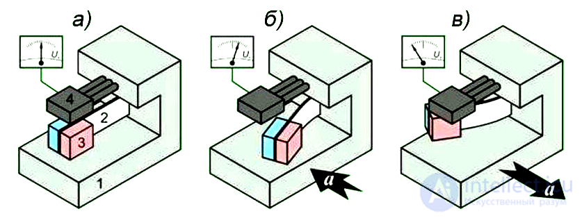
Fig. 3. Vehicle lateral (longitudinal) acceleration sensor
A capacitive lateral acceleration sensor (fig. 4) consists of several series-connected capacitor plates.
Inside housing 1, on suspension 4, a movable capacitor plate 3 with a seismic mass (weight) is mounted, which moves under the action of lateral acceleration a.
Two more capacitor plates 2 are stationary and positioned so that two series-connected capacitors K1 and K2 are formed.
Using contact pads 5, the sensor is connected to the ECU.
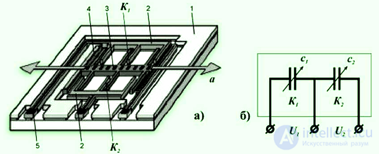
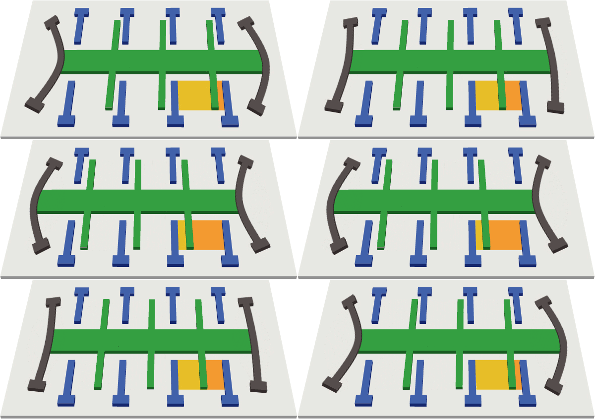
Fig. 4. Capacitive lateral acceleration sensor:
a) design;
b) electrical circuit; 1 - housing; 2 - stationary plate; 3 - movable plate with seismic mass; 4 - suspension; 5 - contact pad
In the absence of acceleration, the measured capacitances C1 and C2 of both capacitors are equal in value.
When lateral acceleration occurs, the massive movable plate, under the action of inertial force, is displaced relative to the stationary plates counter to the acceleration. This changes the distances between the plates and the capacitance of each capacitor; for example, in capacitor K1 the distance between the plates increases, and capacitance C1 decreases; in capacitor K22 the distance between the plates decreases, and capacitance C2 increases.
The main difference between a gyroscope and an accelerometer lies in the operating principles of these hardware components. The first calculates its own angle of tilt relative to the ground, the second measures its own acceleration — but, again, relative to the Earth's surface. In practice, both functions can, in a number of cases, replace each other or successfully complement each other. That is why many mobile devices are equipped with both an accelerometer and a gyroscope.
At the same time, the accelerometer has a number of capabilities that are not available to the gyroscope. In particular — generating signals that allow the distance traveled by the mobile device user to be determined.
Having established what the difference is between the gyroscope and the accelerometer, let us set out its key criteria in the table.
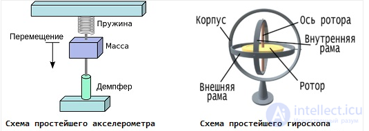
Diagram of an accelerometer and a mechanical gyroscope
Table Comparison of the Gyroscope and the Accelerometer
| Gyroscope | Accelerometer |
| What do they have in common? | |
| Both devices allow determining their position relative to the ground, as well as that of the gadget in which they are installed, and can be used for these purposes simultaneously | |
| What is the difference between them? | |
| Determines its own angle of tilt relative to the ground | Determines acceleration relative to the Earth's surface |
| Cannot be used to measure the duration of a device's movement | Can be used to measure the duration of a device's movement |
In modern communicators, phones and tablets, the accelerometer and gyroscope are also used as important game-control elements. As a result, the player gets the ability to control, for example, a virtual car in some kind of racing game with simple turns, shakes and other movements of the device. And, naturally, the range of games is not limited to racing games alone. There is a huge number of different games that use the gyroscope and accelerometer as a means of control. All this makes the gaming process more engaging and interactive.
In a number of devices, software can also use the accelerometer and gyroscope in a wide variety of cases. For example, on iPhone communicators, in portrait (standard) screen orientation, the calculator is the most ordinary one — only buttons with digits and the simplest arithmetic operations are displayed. But when the device is rotated 90 degrees, the calculator automatically switches to professional mode — buttons with trigonometric, logarithmic and other functions appear.
In addition, on the iPhone, iPod and iPad, the accelerometer is used by the music player: in portrait (vertical) screen orientation, a list of songs/artists/albums is displayed, and when the device is rotated 90 degrees, a transition occurs into a special mode called CoverFlow. Images of album covers appear on the screen, which can be scrolled through with a simple finger movement. It is important to understand that the accelerometer here performs only one function: ensuring the automatic transition from standard mode to CoverFlow mode.
Another application of the sensors described can be seen in navigation mode. For example, you look at the map of the area on a device (with a GPS module, of course). This map — with the help of the gyroscope — is displayed in accordance with your position; in other words, the screen shows a diagram of the area that is directly in front of you. You turn around, and the map on the screen turns too. In fact, the map always corresponds to the direction of your gaze/body. This is very practical.
Finally, it is worth noting the pedometer function that some devices with an accelerometer have (for example, iPod Nano players of the 5th and 6th generations, iPhone communicators). The pedometer allows you to measure the distance traveled during the day (or, for example, the distance you ran over a certain period of time). However, the accuracy of the measurement depends on many factors and is sometimes quite low.
As you can see, the accelerometer and gyroscope are quite useful things, although there is, of course, no vital necessity for them. I would also like to note that the gyro sensor and accelerometer do not have telepathic properties and react to any turns and movements of the device, including accidental ones. This is naturally annoying, and many people simply turn these sensors off. Personally, I use them.
It is worth saying a few separate words about accelerometers (G-sensors) in e-ink readers. Due to the specifics of the e-ink screen (it is distinguished by slowness), a G-sensor in a reader is a very questionable pleasure. If it triggers by mistake, you will have to wait until the image/text on the screen rotates into a mode you don't need, and then — wait until it rotates back.
And false triggers, in fact, are not so rare. For example, you lie down with a reader on a bed or a couch, and the G-sensor sends a signal — the text on the screen needs to be rotated. But you don't need that at all. You wait, rotate the text back. Then you decide to turn on your side. The G-sensor triggers again, and again for nothing. As you can see, it's inconvenient. That is exactly why many e-ink reader users turn off the accelerometer. And that is exactly why I do not recommend making the presence of an accelerometer (as well as a gyro sensor) one of the criteria for choosing a reader. It's better if the reader has the ability to rotate the text/image on the screen with a single button
The gyroscope measures angular velocity and helps determine the orientation of an object. Thanks to the gyroscope, it is possible to accurately track turns and rotations, which is critical for maintaining stability, for example, in drones, virtual reality systems, and video shooting with subsequent image stabilization.
The accelerometer registers linear acceleration along the axes, measuring both dynamic changes (vibrations, sharp movements) and the static component, such as gravity. It is thanks to the accelerometer that a smartphone understands what position it is in, which allows it to automatically change the screen orientation and recognize gestures.
G-sensor is often a marketing name for the accelerometer, used when referring to its ability to measure acceleration in units of g (that is, relative to the acceleration of free fall). Such a sensor can track extreme acceleration values or sharp impacts – for example, to protect a laptop's hard drive or to trigger emergency braking in a car.
Example of use in a smartphone: When the device is rotated, the accelerometer registers the change in tilt, while the gyroscope tracks the rate of rotation. Together, using sensor fusion algorithms, they provide a smooth and precise change in screen orientation. In addition, G-sensor data can be used to determine the force of an impact or sharp movements – for example, to activate power-saving mode or protect the device from damage.
Navigation using an accelerometer — is a method for determining the movement and orientation of an object, based on measurements of linear acceleration. Such systems, often called inertial navigation systems (INS) or “dead reckoning” methods, make it possible to calculate the change in velocity and, upon subsequent integration, the position of the object relative to the starting point. Operating principle: The accelerometer measures acceleration along one or several axes. If the initial velocity is known, then by integrating the acceleration signal over time, the change in velocity can be obtained. Next, a second integration of the velocity gives an estimate of the displacement. However, it is important to remember that any noise or measurement errors accumulate during integration, which can lead to significant drift of the results over time. This feature requires the use of correction and filtering methods, for example, using a Kalman filter. To compensate for these limitations, accelerometers are often combined with gyroscopes and magnetometers as part of a single measurement system (IMU). Gyroscopes register angular velocity, while magnetometers help determine orientation relative to the Earth's magnetic field. Combining the data from such sensors using algorithms, for example, Kalman filters, makes it possible to significantly improve the accuracy of both velocity and position estimates.
Below is a comparison table:
| Sensor | What it measures | Examples of application |
|---|---|---|
| Gyroscope | Angular velocity, rotation | Drone stabilization, VR systems, video shooting, navigation |
| Accelerometer | Linear acceleration (tilts, vibrations) | Automatic screen orientation change, fitness trackers, navigation |
| G-sensor | Acceleration in units of g | Determining impact force, activating emergency modes, protecting data on hard drives |
These sensors are used not only in consumer electronics, but also in the automotive industry, robotics, sports trackers, and even in aerospace technology. Thus, their combined use allows devices to more accurately "understand" their position and dynamics, which increases both ease of use and safety of device operation.
The impact sensor is one of the main elements of a security alarm system. Thanks to this sensor, we, as car owners, can protect them from possible break-ins or theft.
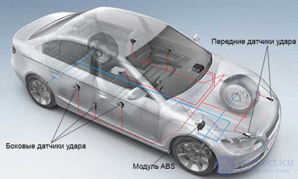
Example of the placement of impact sensors in an SRS system
Impact sensors are used not only in car alarm systems, but also for protecting private homes, commercial premises, the transport of valuables, etc.
Sensors are divided into types depending on their physical operating principle: mechanical, piezoelectric and magnetodynamic.
Piezoelectric impact sensors use the ability of a piezoelectric plate to generate a bending voltage. This type of impact sensor is cheap and easy to install, but has one major drawback — they are very sensitive to high-frequency vibrations and react to the slightest vibrations or side noise, such as the sound of another alarm, thunder, noise and other sounds.
In addition, they are subject to thermal effects, and the sensor's sensitivity increases or decreases depending on the outside temperature.
MAGNETODYNAMIC IMPACT SENSORS OPERATE ON THE PRINCIPLE OF SHAKING A MAGNET NEAR A COIL.
This type of sensor consists of a control magnet mounted on an iron spring. At the moment of impact to the car, the oscillation of the spring is triggered. Due to these oscillations, an electrical signal appears in a multi-point coil, and the force of the impact determines how strong the signal will be.
The advantage of magnetodynamic impact sensors is that the magnet swings only under low-frequency effects on the object or car. In addition, sensors of this type are not affected by temperature changes.
Among specialists, there is a lot of debate about the installation of impact sensors. Some of them believe that impact sensors should be installed on the metal parts of the car and should be firmly secured so that they are not subject to external vibrations.
However, according to other experts, installing sensors on metal is a big mistake, since most of the amplitude is absorbed by the metal, and the sensor cannot read the data correctly and often reacts to weak impacts.
Over the years, many experiments have been conducted to try to answer the question of which place is best suited for installing an impact sensor, and it seems that in recent years it has been decided that the best place — is under the car's dashboard.
Mechanical impact sensors
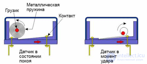
Electromechanical type of sensor with a strip spring
In addition to electromechanical sensors, electronic types are also used in cars, the main element of which is an acceleration sensor (capacitive, inertial, pressure). The design of the electronic elements also includes a signal-processing unit for the acceleration sensor.
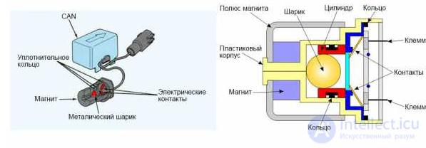
Design of the inertial sensor
The operating principle of the capacitive acceleration sensor comes down to a change in capacitance due to plate displacement. This is achieved by separating the capacitor plates and mounting them on different bases, one of which is stationary, the second – movable. On impact, the same inertial force displaces the movable base with the plates relative to the stationary one. As a result, the capacitance of the capacitive sensor changes. This is registered by the processing unit, which compares the obtained data with tabulated values and, based on this, generates a signal to the control unit.
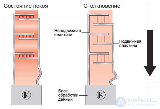
Capacitive acceleration sensor
Other types of sensors operate on the same principle; the only difference comes down to their design. All of them, due to inertia, change some parameters, which forms the basis for generating a signal by the processing unit.
Note that the tuning of impact sensors is carried out based on their installation location. Thus, side elements are usually more sensitive than frontal ones.
To detect an impact in the door area, sensors can be installed that register changes in atmospheric pressure inside the car doors. They can be piezoelectric or capacitive. The first type is based on the piezoelectric effect, and the second on the principle of the capacitive sensor.
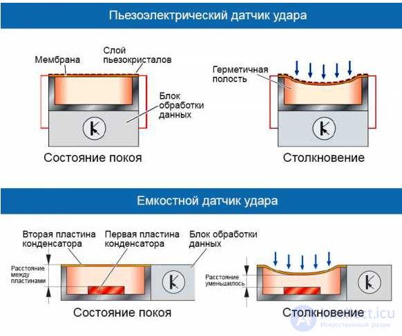
Impact sensors that register changes in pressure
The speed of response of each type of sensor is also taken into account, so several types can be installed simultaneously in a car. For example, pressure sensors are distinguished by high speed of response, which is why they are often installed on the sides (in doors, pillars).
The main advantage of electronic sensors is the determination of the nature of the impact – its force and direction. This is achieved through the tabulated data built into the processing unit.


Comments