
Lecture
USB (Universal Serial Bus) is a serial interface for connecting peripheral devices to computing equipment. It has become extremely widespread and is now the main interface for connecting peripherals to consumer digital equipment.
The interface allows not only data exchange but also powering the peripheral device. The network architecture makes it possible to connect a large number of peripherals even to a device with a single USB connector.
The USB specifications are developed by the international non-profit organization USB Implementers Forum (USB-IF), which brings together developers and manufacturers of equipment with the USB bus. Several versions of the specifications have been produced over time. Nevertheless, the developers have managed to keep a high degree of compatibility between equipment of different generations. The interface specification covers an unprecedentedly wide range of issues concerning the connection of peripheral devices and their interaction with a computer system:
An electronic device is being developed that, when connected to a sensor, measures micro-displacement and sends the result to a PC, where it is displayed in a graphical form convenient for the operator. The measuring instrument is intended for use in mechanical engineering.
A little about how it all works
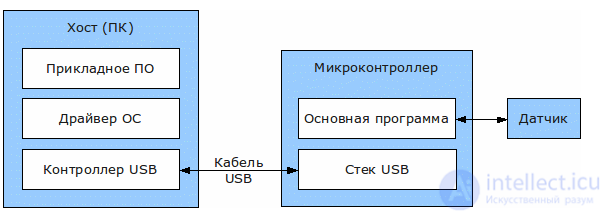
The diagram shows the main players involved in the life of the device being developed.
The microcontroller is the main element of the device: it sends control signals to the sensor and receives the response from which it calculates the measurement result. With the implemented USB stack, data exchange with the host essentially comes down to working with read and write buffers. Because the measurement algorithm does not require much computing power and the period of one measurement is 100-150 ms, the at90usb162 microcontroller (8-bit, 16 MHz, 16 KB) was chosen. This MCU has hardware USB support, which greatly simplifies the software implementation of the USB stack. However, I did not have to implement the stack or initialize the MCU myself, thanks to the USB Generic HID Implementation example from the accompanying software package. Alternatives to the vendor examples for AVR include the LUFA framework (MIT license) for AT90USBxxxx and ATMEGAxxUx, and the fully software implementation of the stack, V-USB (GPL or commercial license), which makes it possible to work with AVR MCUs that have no hardware USB support.
A few words about the abbreviation HID. This is a class of USB devices intended for human data input: keyboards, mice, game controllers. Such devices are expected to transfer a small amount of information, as does the device being developed: packets of 8 bytes at intervals of 100-150 ms. The main convenience of working with devices of this class is that the OS has a standard driver for them, which saves you from writing your own.
In my case the host (master) is the PC, or more precisely the USB controller built into the motherboard. According to the descriptor (description) of my device, the host polls it for new packets with a period of about 20 ms. The application software collects the data received by the host, does some light processing and draws indicators resembling car speedometers that show the measured values. It displays a list of connected sensors and their settings, which can be changed: the changes are sent to the device and saved in non-volatile memory.
One of the ideas behind the application is cross-platform support, so it is developed with the Qt framework in C++, and calls to the OS for reading and sending data go through the libusb library. Over the last few months there has been active development of the libusb v1.0 backend for Windows; it is already reported to be in pre-release status and, more importantly, everything seems to work for me with it. There is also a port of libusb v0.1 for Windows, LibUsb-Win32. Working through the WinAPI is covered in detail, with examples in Visual Basic and Visual C#, in the book USB Complete (about the book). I tried the WinAPI and did not like it.
VID and PID
When releasing its USB device, a company must assign it a vendor identifier (vid – vendor id) and a product identifier (pid – product id, not to be confused with the serial number). Formally, uniqueness is required to prevent conflicts between device drivers in the OS. Although I suspect that it is more a way for the creators of the standard to make money than the only possible technical solution. Still, I will not, of course, condemn them for wanting to earn money on the standard they created themselves.
So, a peripheral manufacturer has two ways to obtain its own vid:
For those who cannot afford such money, chip manufacturers offer various options for using their vid and pid:
Published here is a Russian translation of the unique document USB in a NutShell, which makes the first acquaintance with the USB protocol easier for developers all over the world. It is the best starting point for beginners, and a decent way to clear the minds of more experienced developers (who think they already know something). If some terms and abbreviations are unclear, use the [Terms] section at the end of the article.
Getting started with the USB protocol looks daunting. For example, the 650 pages of the USB 2.0 standard alone can put off any beginner. And that is only the beginning of a long list of related standards for USB. USB class specifications, such as the HID Class Specification with a general description of how devices (keyboards, mice, etc.) that fall into the HID (Human Interface Devices) class work, take another 97 pages. If you are developing a USB host, you need to choose one of three Host Controller Interface Standards (Host Controller Interface Standards). None of them is detailed in the USB 2.0 specification.
The good news is that there is no need to read the entire USB standard. Some chapters came out of the marketing department, and others deal with the low level, which is taken care of by your USB controller chip and by the host together with the hub designers. Let us take a short tour through the various chapters of the USB 2.0 specification and briefly review the main points.
| Chapter | Title | Description | Pages |
| 1 | Introduction | Covers the purpose and scope of USB. The most important piece of information in this part is the reference to the Universal Serial Bus Device Class Specifications. There is no need to read this chapter. | 2 |
| 2 | Terms and Abbreviations | This chapter is self-explanatory – the usual necessary evil of any standard. | 8 |
| 3 | Background | States the goals of USB, such as Plug’n’Play and ease of use for the end user (not the developer). Introduces the Low, Full and High Speed rates with a list of features obtained for marketing purposes. There is no need to read this chapter. | 4 |
| 4 | Architectural Overview | This is where you can start reading. This part gives a basic overview of the USB system, including topology, data rates, data flow types, basic electrical parameters, etc. | 10 |
| 5 | USB Data Flow Model | This chapter begins the story of how data is transferred over the Universal Serial Bus. It introduces and describes terms such as endpoints and pipes. Most of the chapter is devoted to each type of data flow (Control, Interrupt, Isochronous and Bulk). It is important to know each transfer type and its properties, although this is somewhat hard for a beginner. | 60 |
| 6 | Mechanical | The chapter describes the two standard connectors. The important information here is that the type A connector faces downstream (toward USB devices) and the type B connector faces upstream (toward the USB host). This way it is impossible to plug a cable into two upstream ports. All detachable cables must be full/high speed, while any low speed cable must have the appropriate pinout. After a quick look through the connectors, you can skip this part if you are not going to manufacture USB connectors and/or cables. PCB designers can find the standard connector footprints. | 33 |
| 7 | Electrical | The chapter covers low-level electrical signals, including line impedance, rise/fall times, driver (transmitter)/receiver specifications and bit-level encoding, bit stuffing, etc. The most important parts of this chapter describe identifying the device speed by connecting a pull-up resistor to one of the data lines, and the comparison of bus powered devices and self powered devices. You can skip this chapter if you are not designing USB transceiver chips. A good datasheet for a USB device (chip) specifies the values of the bus termination resistors you will need to match the bus impedance. | 75 |
| 8 | Protocol Layer | Now we begin looking at the protocol layers. This chapter describes USB packets at the level of individual bytes, including the sync, pid, address, endpoint and CRC fields. After that comes the transition to the next protocol layer, USB transactions. Most developers pay no attention to these low-level protocol layers, since the USB device chips they use take care of them. However, understanding the status reporting and handshaking procedures is important here. | 45 |
| 9 | USB Device Framework | This is the most frequently used chapter of the entire specification, and the only one I bothered to print out and bind. It describes bus enumeration and request codes (set address, get descriptor, etc.), the layer of the USB protocol most used in programming, important for programmers and designers. This chapter must be read carefully. | 36 |
| 10 | USB Host: Hardware and Software | This chapter covers host-related issues. It describes the generation of frames and microframes, host controller requirements, software mechanisms and the USB driver model. You can skip this chapter if you are not designing a USB host. | 23 |
| 11 | Hub Specification | Describes the operation of USB hubs, including hub configuration, transaction splitting, standard descriptors for the hub class, etc. You can skip this chapter if you are not designing hubs. | 143 |
Now we can start reading the parts of the standard that we really need. If you are developing drivers (software) for USB peripherals, you will need only the following parts:
Peripheral hardware developers (electronics) will need only the following chapters:
USB in a NutShell for Peripheral Designers
Now let us assume (and this is certainly true) that (1) most of us are designing USB peripherals and (2) have read the standard, but afterwards have no idea how to actually implement the device being designed. In the next 7 chapters we will focus on the parts of the standard needed to develop a USB device. This will let you "plug into" USB and continue development according to your application (the purpose of the USB device).
The USB 1.1 standard was not sophisticated enough for High Speed, and grew into USB 2.0. To make the fundamental principles of USB easier to understand, we will skip much of what relates directly to High Speed USB devices.
Introduction to the Universal Serial Bus (USB)
USB version 1.1 supports two speeds – full speed mode at 12 Mbits/s and low speed mode at 1.5 Mbits/s. The 1.5 Mbits/s mode is slower and less sensitive to EMI (interference), which reduces the cost of ferrite rings and lowers the requirements for component quality. For example, quartz crystals can be replaced with cheap resonators. USB 2.0, which currently dominates desktops and laptops, raises the bar to 480Mbits/s. These 480Mbits/s are designated High Speed mode, and by this parameter it can compete with the Firewire serial bus.
USB Speeds
| Specification | Speed | USB standard |
|---|---|---|
| Low-Speed | up to 1.5 Mbit/s | USB 1.0 |
| Full-Speed | up to 12 Mbit/s | USB 1.1 |
| High-speed | up to 480 Mbit/s | USB 2.0 |
| SuperSpeed | up to 5 Gbit/s | USB 3.0 / USB 3.1 Gen 1 / USB 3.2 Gen 1 |
| SuperSpeed+ 10Gbps | up to 10 Gbit/s | USB 3.1 Gen 2 / USB 3.2 Gen 2 |
| SuperSpeed++ 20Gbps | up to 20 Gbit/s | USB 3.2 Gen 2x2 |
New naming scheme
After the release of the USB 3.2 standard, USB-IF introduced a new naming scheme[27]. To help companies with branding the different transfer modes, USB-IF recommends calling the 5, 10 and 20 Gbit/s transfer modes SuperSpeed USB 5Gbps, SuperSpeed USB 10Gbps and SuperSpeed USB 20Gbps respectively[28]:
| Specification | Old name | Original name | Transfer mode | Marketing name (USB-IF branding) | Speed | Transfer rate | Picture |
|---|---|---|---|---|---|---|---|
| USB 3.2 Gen 1 | USB 3.1 Gen 1 | USB 3.0 | Gen 1 | SuperSpeed USB 5Gbps | 5 Gbit/s | 500 MB/s |  |
| USB 3.2 Gen 2 | USB 3.1 Gen 2 | USB 3.1 | Gen 2 | SuperSpeed USB 10Gbps | 10 Gbit/s | 1.21 GB/s |  |
| USB 3.2 Gen 2x2 | --- | USB 3.2 | Gen 2 × 2 | SuperSpeed USB 20Gbps | 20 Gbit/s | 2.42 GB/s |  |
The Universal Serial Bus is a bus controlled exclusively by the host. One and only one host is allowed on the bus. The USB specification itself does not support any form of multi-hosting. However, the On-The-Go specification, introduced with the USB 2.0 standard, adds the Host Negotiation Protocol, which allows two USB devices to negotiate which of them will act as the host. This is intended for, and limited to, single point-to-point connections, such as a mobile phone and a personal organizer, and does not extend to hubs and computer configurations. The USB host is responsible for initiating all transactions and for allocating bandwidth. Data can be sent using various transaction methods, using a token-based protocol.
In my opinion, the USB bus topology is somewhat limited. One of the initial goals of USB was to reduce the number of cables plugged into the back (or front) of your PC. Apple fans may say that this idea came from the Apple Desktop Bus, where the keyboard, mouse and other peripherals can be connected to one another (in a daisy chain topology) using a single cable.
However, USB uses a "tiered star" topology, similar to the 10BaseT Ethernet topology. This implies the possible use of hubs, which adds inconvenience – more boxes on your desk and more cables. But it is not as bad as it may seem at first. Many devices have hubs integrated into them. For example, your keyboard may contain a hub connected to the computer. Your mouse and other devices (a digital camera, etc.) can simply be plugged into the keyboard. Many monitors also have a built-in hub.
The tiered star topology has some advantages over a simple daisy chain topology. First, the power consumption of each device can be monitored, and switching and overloads do not affect the operation of other USB devices. High, full and low speed devices can all be supported simultaneously – the hub filters high speed and full speed transactions, so that lower-speed devices do not receive data at too high a rate.
Up to 127 devices can be connected to a single USB bus at the same time. Need more devices? Simply add another port/host. Many older USB hosts had 2 ports, and many manufacturers found this insufficient and began producing host cards and motherboards with 4 and 5 ports, with internal USB ports (for hard drives, for example). Early hosts had a single USB controller, and the two ports shared the available USB bandwidth between them. As bandwidth requirements grew, we now see multi-port boards with two or more controllers, allowing separate data channels to be provided.
USB host controllers have their own specifications. In the USB 1.1 standard there are two Host Controller Interface specifications:
With the arrival of USB 2.0, a new Host Controller Interface Specification was needed to describe the register-level details specific to USB 2.0. EHCI (Enhanced Host Controller Interface) was born. Well-known vendors including Intel, Compaq, NEC, Lucent and Microsoft joined forces to provide us with a single interface standard and thus only one new driver to implement in operating systems. About time.
USB, as its name implies, is a serial bus. It uses 4 shielded wires, two of which carry power (+5v & GND). The other two are a twisted pair of differential data signals. The NRZI (Non Return to Zero Invert) encoding scheme is used to transmit data, with a sync field to synchronize the host and receiver clocks.
USB supports "hot" (plug’n’play) connection with dynamically loaded and unloaded drivers. The user simply plugs in the device, thereby connecting it to the bus. The host detects the attachment, queries the freshly inserted device and loads the appropriate driver, indicating the loading moment with an hourglass on the screen (if the driver for the USB device is already installed in the system). The end user does not worry about termination, about IRQ (interrupts) and port addresses, or about rebooting the computer (no reboot is required). When the user has finished working with the USB device, he simply pulls it out (or disconnects the cable), and the host detects the absence of the device and automatically unloads the driver.
The appropriate driver is loaded (selected) based on the PID/VID (Product ID/Vendor ID) combination. The VID is issued by the USB Implementors Forum for a fee, and this is yet another stumbling block for USB. The latest pricing information can be found at http://www.usb.org/developers/vendor/.
Other standards organizations provide additional VIDs for non-commercial use, such as education, development and so on (hobby electronics). The USB Implementors Forum should still provide this service. In such cases you can use a VID assigned to the vendor of your development system. For example, most chip manufacturers have VID/PID combinations that you can use for your chips, and these VID/PIDs are known not to exist in commercial devices. Other chip manufacturers may even sell you a private PID for your commercial device, to be used together with the manufacturer's VID.
Another more noteworthy feature of USB is its transfer modes. USB supports Control, Interrupt, Bulk and Isochronous transfers. While we will look at the other transfer modes later, Isochronous mode allows a device to reserve a certain portion of the bandwidth with a guaranteed latency. This is ideal for audio and video applications, where channel overload can lead to noticeable data loss or a reduced frame rate. Each transfer mode gives the developer different trade-offs in error detection and recovery, guaranteed latency and bandwidth.
Connectors
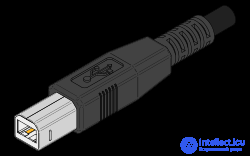
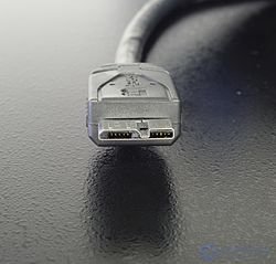
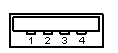
All devices have an upstream connection to the host, and all hosts have a downstream connection to the device. The upstream and downstream connectors are not mechanically interchangeable, which eliminates illegal loop-back connections on hubs, such as plugging a downstream port into a downstream port. Two kinds of connectors are commonly used, called type A and type B, which are shown below.
|
|
|
|
| Type A USB Connector (socket, pin numbering seen from the outside) |
Type B USB Connector (socket, pin numbering seen from the outside) |
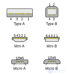
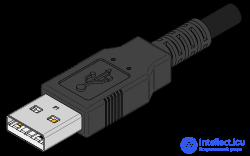
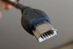
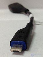
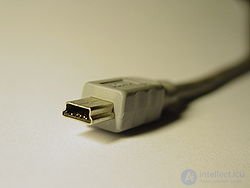
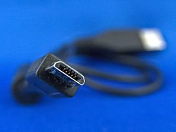
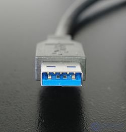
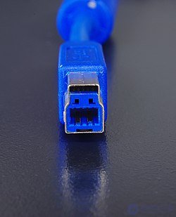
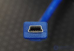
Specification 1.0 defined two types of connectors: A, on the side of the USB controller or hub, and B, on the side of the peripheral device. Miniature connectors were later developed for using USB in portable and mobile devices, and were called Mini-USB. A new version of the miniature connectors, called Micro-USB, was introduced by the USB-IF on January 4, 2007.
| Standard | Mini | Micro | |
|---|---|---|---|
| Type A | 4×12 mm
 |
3×7 mm
 |
2×7 mm
 |
| Type B | 7×8 mm
 |
3×7 mm
 |
2×7 mm
 |
| Standard | Mini | Micro | |
|---|---|---|---|
| Type A |
 |
||
| Type B |
 |
 |
 |
| Type C |
 |
The Type A plug (i.e. the male connector) always faces upstream (i.e. toward the host). The Type A socket (i.e. the female connector) can usually be found on the wall of a host or hub. For example, type A sockets are located on computer motherboards and hubs. Type B plugs always connect downstream, and therefore type B sockets are located on USB devices. At first glance this sounds rather confusing, but you can figure it out =).
It is interesting to find in some computer stores type A <--> type A cables with straight-through wiring, and numerous USB-type chargers. This contradicts the USB specification. Devices that act as an adapter between a type A plug and a type A plug are a bridge used to connect two computers to each other. Other prohibited cables are USB extension cables, which have a plug (either type A or type B) on one end and a socket (either type A or type B) on the other end. These cables violate the USB cable length requirements.
USB 2.0 includes an erratum that introduces mini-USB B connectors. Detailed information on these connectors can be found in the Mini-B Connector Engineering Change Notice. The reason mini connectors appeared was to enable the use of USB in small electronic devices such as mobile phones and organizers. The regular type B connector is too large to be simply used in these devices.
More recently, the On-The-Go specification was developed, which adds peer-to-peer functionality to USB. It introduces USB hosts in mobile phones and electronic organizers, and so the specification includes mini-A plugs, mini-A receptacles and mini-AB receptacles. I expect that mini USB cables will soon become widespread, along with a set of mini-to-standard converter cables.
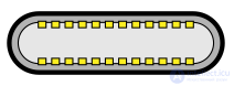
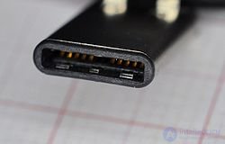
USB Type-C or USB-C is a USB specification for a universal compact reversible 24-pin connector for USB devices and USB cables .
Version 1.0 of the USB Type-C connector specification was published by the USB Implementers Forum in August 2014 . It was developed at the same time as the USB 3.1 specification.
The USB Type-C connector can be used on peripheral devices and computers. USB Type-C is the new generation of connectors and cables, replacing the type A and B connectors of previous USB standards . Unlike previous versions, the USB-C connector is horizontally symmetrical and plugs into the device either way up. That is, the connector can be flipped relative to the socket. It supports the USB 2.0, USB 3.0 and USB 3.1 Gen 2 standards.
Using a USB Type-C connector does not guarantee that the device implements the high-speed USB 3.1 Gen1/Gen2 standard or the USB Power Delivery protocol .
The USB Type-C connector also works in alternate modes, in which the pins carry data using other protocols:
 DisplayPort alternate mode — published by VESA in September 2014, supports the DisplayPort 1.3 standard[11];
 Thunderbolt alternate mode — support for the Thunderbolt 3 standard
  HDMI alternate mode — announced in September 2016 , supports HDMI 1.4b.
To implement the DisplayPort and HDMI alternate modes, an adapter cable ending in a plug of the corresponding physical interface is used. The MHL and Thunderbolt (20 Gbps) modes use a standard Type-C cable; the high-speed Thunderbolt 3 mode (40 Gbps), like the high-power USB Power Delivery 2.0 modes, requires special cables marked with an electronic chip as compatible.
For detachable cables working in alternate mode, four high-speed (SuperSpeed) pairs and two Sideband pins can be used. For docking stations, detachable devices and non-detachable (permanent) cables, the two D+/D- pins and one configuration pin can also be used. The modes are configured through the configuration pin using vendor-defined messages (VDM).
Not all alternate modes are implemented in every device with a USB Type-C connector; the supported alternate modes are indicated by the corresponding logos next to the connector[22].
The possibility of using this connector for other high-speed serial protocols, such as PCI Express and Base-T Ethernet, is being studied[2
| Pin number | Wire color | Function |
| 1 | Red | VBUS (5 volts) |
| 2 | White | D- |
| 3 | Green | D+ |
| 4 | Black | Ground |
USB cables use a standard color coding for the insulation of the internal conductors, which makes it easier to identify wires from manufacturer to manufacturer. The standard specifies various electrical parameters for cables. It is interesting to read the included original USB 1.0 specification in detail. You would understand the stated electrical attributes, but paragraph 6.3.1.2 suggests frosted white as the recommended color for filling USB cables – how boring! USB 1.1 and USB 2.0 relax the recommendation to Black, Gray or Natural.
PCB designers will find the standard footprints and connector pinouts in part 6 of the standard.

Unlike in previous versions, the name of the protocol is written as one word, with no space between the word "USB" and the digit "4".
The fourth-version specification was published on August 29, 2019[29][30]. The new base protocol raises the maximum speed to 40 Gbit/s (when using compatible Type-C cables), while retaining backward compatibility with USB 3.2, USB 2.0 and, optionally, Thunderbolt 3[31][32][33].
On September 30, 2021, new USB Type-C cable logos were introduced which, in addition to the data transfer rate, also show the charging power: 60 W or 240 W[34][35][36].
Inter-Chip USB (Eng.)Rus. (IC-USB) and High Speed Inter-Chip USB (HSIC) are simplified versions of USB 2.0 for non-switched connection of chips within a single device. The simplification is achieved by replacing the USB physical layer from asynchronous to synchronous, dropping speed switching and connection detection, dropping electrical protection of the drivers and reducing their power. The logical part of USB is unchanged (including the bus state logic). IC-USB defines the connection of Full Speed (12 Mbit/s) devices; HSIC defines the connection of High Speed (480 Mbit/s) devices.
The first version of the IC-USB standard was adopted in 2006. The first version of the HSIC standard was adopted in 2007[37]. HSIC uses two digital lines with LVCMOS logic levels (1.2 volts): STROBE and DATA. The maximum conductor length is 10 cm. The synchronous interface provides a throughput of 480 Mbit/s at a clock frequency of 240 MHz. The HSIC physical layer driver consumes 50% less power and occupies 75% less die area than a traditional USB 2.0 driver[38].
In 2012 the first version of the Inter-Chip USB specifications for USB 3.0 was adopted[39].

Wireless USB is a USB technology (the official specification has been available since May 2005) that makes it possible to set up a wireless connection with a high data rate (up to 480 Mbit/s at a distance of 3 meters and up to 110 Mbit/s at a distance of 10 meters).
On July 23, 2007, the USB-IF announced the certification of the first six consumer products supporting Wireless USB[40].
In 2013 the MA-USB specification was introduced, allowing the USB protocol to be encapsulated in existing communication channels, including WiFi and WiGig.
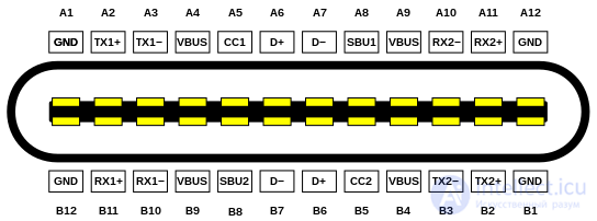
| Pin | Name | Description | Pin | Name | Description |
|---|---|---|---|---|---|
| A1 | GND | Ground | B12 | GND | Ground |
| A2 | TX1+ | SuperSpeed differential pair #1[a], transmit+ | B11 | RX1+ | SuperSpeed differential pair #2[a], receive+ |
| A3 | TX1- | SuperSpeed differential pair #1[a], transmit- | B10 | RX1- | SuperSpeed differential pair #2[a], receive- |
| A4 | VBUS | Power positive | B9 | VBUS | Power positive |
| A5 | CC1 | Configuration channel (or negotiation) | B8 | SBU2 | Sideband channel |
| A6 | D+ | High-Speed differential pair[b], position 1, data+ | B7 | D- | High-Speed differential pair[b], position 2[c], data- |
| A7 | D- | High-Speed differential pair[b], position 1, data- | B6 | D+ | High-Speed differential pair[b], position 2[c], data+ |
| A8 | SBU1 | Sideband channel | B5 | CC2 | Configuration channel (or negotiation) |
| A9 | VBUS | Power positive | B4 | VBUS | Power positive |
| A10 | RX2- | SuperSpeed differential pair #4[a], receive- | B3 | TX2- | SuperSpeed differential pair #3[a], transmit- |
| A11 | RX2+ | SuperSpeed differential pair #4[a], receive+ | B2 | TX2+ | SuperSpeed differential pair #3[a], transmit+ |
| A12 | GND | Ground | B1 | GND | Ground |
|
| Connector #1 of the Type-C cable | Type-C cable | Connector #2 of the Type-C cable | ||||
|---|---|---|---|---|---|---|
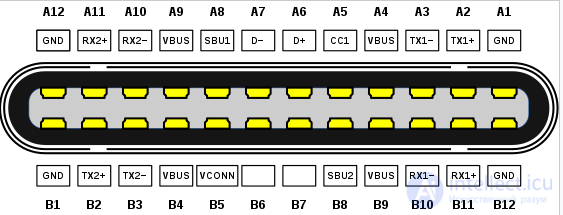
| Pin | Name | Conductor insulation color | Name | Description | Pin | Name |
| Braid | Shield | Cable braid | Shield | Outer cable braid | Braid | Shield |
| A1, B1, A12, B12 | GND | Tinned | GND_PWRrt1 GND_PWRrt2 |
Common ground | A1, B1, A12, B12 | GND |
| A4, B4, A9, B9 | VBUS | Red | PWR_VBUS1 PWR_VBUS2 |
VBUS power | A4, B4, A9, B9 | VBUS |
| B5 | VCONN | Yellow | PWR_VCONN | VCONN power | B5 | VCONN |
| A5 | CC | Blue | CC | Configuration channel | A5 | CC |
| A6 | Dp1 | White | UTP_Dp | Unshielded differential pair, positive | A6 | Dp1 |
| A7 | Dn1 | Green | UTP_Dn | Unshielded differential pair, negative | A7 | Dn1 |
| A8 | SBU1 | Red | SBU_A | Sideband use channel A | B8 | SBU2 |
| B8 | SBU2 | Black | SBU_B | Sideband use channel B | A8 | SBU1 |
| A2 | SSTXp1 | Yellow * | SDPp1 | Shielded differential pair #1, positive | B11 | SSRXp1 |
| A3 | SSTXn1 | Brown * | SDPn1 | Shielded differential pair #1, negative | B10 | SSRXn1 |
| B11 | SSRXp1 | Green * | SDPp2 | Shielded differential pair #2, positive | A2 | SSTXp1 |
| B10 | SSRXn1 | Orange * | SDPn2 | Shielded differential pair #2, negative | A3 | SSTXn1 |
| B2 | SSTXp2 | White * | SDPp3 | Shielded differential pair #3, positive | A11 | SSRXp2 |
| B3 | SSTXn2 | Black * | SDPn3 | Shielded differential pair #3, negative | A10 | SSRXn2 |
| A11 | SSRXp2 | Red * | SDPp4 | Shielded differential pair #4, positive | B2 | SSTXp2 |
| A10 | SSRXn2 | Blue * | SDPn4 | Shielded differential pair #4, negative | B3 | SSTXn2 |
| * Conductor insulation colors are not defined by the standard |
Electrical specification
You do not need the electrical specifications of chapter 7 unless you are designing USB device/transceiver chips or a USB host/hub. We will briefly go over the main points of this chapter.
As we already mentioned, USB uses a pair of wires for data transmission. Encoding uses the NRZI (Non Return to Zero Inverted) principle, and bit stuffing is applied to ensure the necessary level transitions in the data stream. On low speed and full speed devices, a differential '1' is transmitted by raising D+ above +2.8V through a 15KOhm resistor connected to +3.6V, and D- below +0.3V through a 1.5KOhm resistor connected to ground. A differential '0' is transmitted in the same way, only with the levels reversed: D- above 2.8V and D+ below 0.3V.
The receiver recognizes a differential '1' if the D+ level is greater than D- by 200mV, and a differential '0' if D+ is less than D- by 200mV. The polarity of the signal is inverted depending on the bus speed. The terms 'J' and 'K' states are used to denote logic levels. At low speed, the 'J' state is a differential 0. At high speed, the 'J' state is a differential 1.
USB transceivers have both differential and single-ended outputs. Certain bus states are indicated by single-ended signals on D+, D-, or both at once. For example, the SE0 signal is single-ended and can be used to indicate a device reset if it is held for longer than 10 ms. The SE0 signal is generated by holding both D- and D+ at a low level (< 0.3V). It is important to know about the implementation of single-ended and differential outputs if you use a transceiver and an FPGA as a USB device. You cannot make it work with only a differential output.
The low speed/full speed bus has a characteristic impedance of 90 Ohm +/- 15%. Therefore, it is important to check the datasheet when choosing the values of the series resistors for D+ and D-. Any good datasheet specifies the resistor values and their tolerances.
High Speed mode (480Mbits/s) uses a constant current of 17.78 mA for signaling, in order to reduce noise.
Speed identification
A USB device must indicate its speed by pulling the D+ or D- line up to 3.3V. A full speed device, as shown in the figure below, uses a pull up resistor connected to D+ to tell the host that it is a full speed device. The pull up resistors on the device side are used by the host or hub to detect the presence of a device on the bus (whether a device is plugged into the USB port). Without a pull up resistor, nothing is considered to be connected to the USB bus. Some devices have this resistor built into the chip (it can be switched on and off in software under firmware control), while others require an external resistor.
Take, for example, Philips Semiconductor's SoftConnectTM technology. When connected to the bus, the microcontroller initializes the USB device function before it enables the speed-identification pull up resistor that indicates the device is connected to the bus. If the pull up resistor were connected to Vbus, the device would connect to the bus immediately as soon as it is plugged into a USB port. In that case the host could try to reset the device and request a descriptor while the device's microcontroller has not yet initialized the USB device function (is not ready to handle USB requests).
Other vendors, such as Cypress Semiconductor, also use a programmable resistor for Re-NumerationTM technology in their EzUSB devices, where on connection the device is first identified as a programmable USB device, and then, after software is loaded into the device, it disconnects from the bus and, under the control of the loaded firmware, enumerates as a different USB device (all of this happens invisibly to the user). Many EzUSB devices have no built-in Flash memory or OTP ROM for storing code. They load the code over the USB connection.
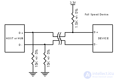 |
| Figure 2: A Full Speed USB device has a pull up resistor connected to D+ |
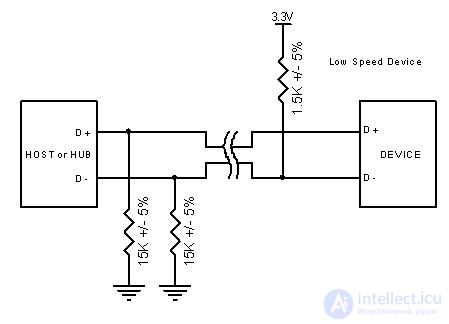 |
| Figure 3: A Low Speed USB device has a pull up resistor connected to D- |
Note that we have not covered speed identification for High Speed mode. High speed devices begin operation by connecting as full speed (1.5k to 3.3V on the D+ signal). After the connection is established and a reset occurs, the device switches to a high speed connection if the hub or host supports it. When the device operates in high speed mode, the pull up resistor is disconnected to preserve the balance of the line.
For a device to be USB 2.0 compliant, it is not required to support high-speed mode. This allows cheaper devices to be produced when speed is not important. The same holds for a USB 1.1 low speed device, which is not required to support full speed.
However, a high-speed device must not be required to support low speed mode. It only has to support full speed mode for the initial connection, and then switch to high speed mode after successful negotiation. A USB 2.0 compliant downstream device (hub or host) must support all three modes: high speed, full speed and low speed.
Power (VBUS)
One of the benefits of USB is bus-powered devices: devices that can draw power from the bus and need no additional jacks or cables. However, many people get confused by this option without considering the necessary criteria.
A USB device states its power consumption in units of 2mA in the configuration descriptor, which we will look at in detail later. A device may not increase its power consumption above the value stated at enumeration, even if its external power is lost. There are 3 classes of USB functions:
Low power bus-powered functions draw their power entirely from VBUS and may not draw more than 1 unit load. The USB specification defines a unit load as 100mA. Low power bus-powered functions must also be designed so that they can operate with VBUS dropping as low as 4.40V and rising as high as 5.25V, measured at the device's upstream connector. For most devices, LDO regulators are mandatory for 3.3V.
High power bus-powered functions draw power only from USB and may not draw more than 1 unit load until they have been configured by the host, after which they may draw up to 5 unit loads (500mA Max), granted according to the amount requested in the descriptor. High power bus-powered functions must be able to pass detection and enumeration at a minimum voltage of 4.40V. When operating at full load, the minimum for VBUS is 4.75 V and the maximum is 5.25V. Here too the measurements are taken at the upstream connector.
Self-powered functions may draw up to 1 unit load from the bus and get the remainder of their power from an external source. If the external power source is lost, it must be possible to draw no more than 1 unit load from the USB bus. Self-powered functions are easier to design, since there are no problems with power consumption. A one-unit load on the bus allows detection and enumeration to be carried out without a main/auxiliary power source.
No USB device, regardless of its power type, may supply power to the VBUS wire on its upstream port. If VBUS is lost, the device must remove power from the D+/D- pull-up resistors used for speed identification within 10 seconds.
Another VBUS consideration is inrush current, which must be limited. This is covered in paragraph 7.2.4.1 of the USB specification and is usually overlooked. Inrush current arises from the capacitance in your device between VBUS and ground. For this reason the specification sets the maximum decoupling capacitance you may have in your device: 10uF. When you unplug the device, the flowing current produces a self-induction EMF (because of the inductance of the USB cable), which can reach a large value. To protect against this, a minimum decoupling capacitance of 1uF must be present on VBUS.
A typical bus-powered device cannot draw more than a very reasonable 500mA. You may ask: what complications could there be here? Perhaps Suspend Mode?
Suspend Mode Consumption
Suspend mode is mandatory for all devices. During suspend, additional restrictions come into force. The maximum suspend current is proportional to the rated load in units. For a device with a load current of 1 unit, the maximum suspend current (by default) is 500uA. This includes the current through the pull-up resistors on the bus. In the hub, both the D- and D+ lines have 15 KOhm pull-down resistors. These pull-down resistors together with the series resistor in the device (the 1.5 KOhm pull-up) create a total load of 16.5 KOhm on VTERM, normally 3.3v. Thus this resistor draws 200uA even before start-up.
In addition, for many devices you must take the 3.3V regulator into account. Many USB devices run from 3.3V, for example the PDIUSBD11. Linear regulators are usually very inefficient at average static currents on the order of 600uA, so more efficient and therefore more expensive regulators are required. In most cases you must also reduce the microcontroller clock frequency, or stop the microcontroller clock altogether, to fit within the 500uA limit.
Translator's note: many firmware developers do not bother handling Suspend mode. For example, among designs based on the V-USB library, I have not come across any projects that support Suspend mode.
Many developers on the USB Implementor's Forum ask what problems will occur if the Suspend current limit is exceeded. It goes without saying that most hosts and hubs cannot detect an overload of that size, and consequently your device may draw 5 mA or even 10 mA and still work normally – but you would still be violating the requirements of the USB specification. However, during normal operation (not in Suspend mode), if you try to exceed your declared allowable load by 100mA, the hub or host will almost certainly detect this and disconnect your device in the interest of bus integrity.
Of course, these design issues can be avoided if you design a self-powered USB device. Suspend currents do not matter for desktops, but with the introduction of the On-The-Go specification, mobile phones and mobile organizers can become USB hosts. Excess power consumption by your USB devices will have an adverse effect on the battery life of the mobile device.
Entering Suspend Mode
A USB device is suspended (enters Suspend mode) when there has been no activity on the bus for more than 3.0 ms. During the following 7 ms the device must shut down and draw no more current than the specified suspend current. Thus, 10 ms after bus activity stops, the current drawn from it must not exceed the suspend current. To maintain its connection to a suspended hub or host, the device must still supply power to the pull-up load resistor that determines the speed selection during Suspend mode.
USB has a start of frame (SOF) packet, which is sent onto the bus strictly periodically (every 1 ms for low speed and full speed) to keep it active. This prevents the bus from becoming inactive (entering suspend mode) when there is no data on the bus.
The term "Global Suspend" is used when the entire USB bus enters suspend mode as a whole. However, a selected device can also be suspended by sending a command to the hub to which the device is connected. This is called "Selective Suspend."
The device will resume operation as soon as it receives any "non-idle" signal. If the device has remote wakeup enabled, it can signal the host that it needs to exit Suspend mode (resume).
Data Signalling Rate
Another area that is often overlooked is the tolerance on the USB clock. This information is in section 7.1.11 of the USB specification.
These tolerances allow inexpensive resonators to be used for low speed devices, but rule them out for full speed or high speed devices.
Unlike RS-232 and similar serial interfaces, where the format of the transmitted data is not defined, USB is built from several protocol layers. It sounds complicated, but do not despair. Once you understand what is going on, you only need to worry about the higher-level protocols. In fact, most USB controllers take care of the lower protocol layers, making them invisible to the end developer.
Each USB transaction consists of:
As we have already mentioned, USB is a bus in which the host is in charge. The host starts all transactions. The first packet,
продолжение следует...
Часть 1 All About USB: USB Interface Programming and Working with USB Peripherals
Часть 2 Communication Method in the USB Specification - All About USB:
Часть 3 Chapter 6: USB Requests - All About USB: USB Interface
Часть 4 Terms - All About USB: USB Interface Programming and Working


Comments