
Lecture
Это продолжение увлекательной статьи про usb.
...
includes all the interface descriptors and endpoint descriptors in use. The wTotalLength field reflects the number of bytes in the hierarchy.
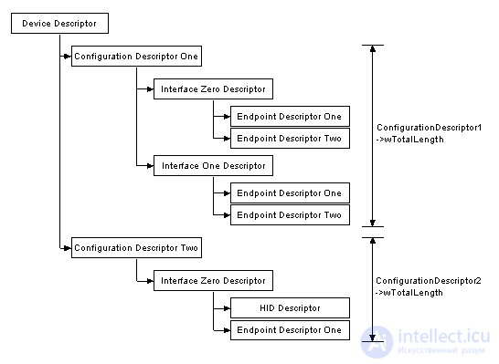
Interface Descriptors
An interface descriptor can be thought of as a header for a collection of endpoints grouped into a functional group that implements a feature of the device. The interface descriptor has the following format.
|
Offset |
Field |
Size |
Value |
Description |
|
0 |
bLength |
1 |
Number |
Size of the descriptor in bytes (9 bytes) |
|
1 |
bDescriptorType |
1 |
Constant |
Interface descriptor (0x04) |
|
2 |
bInterfaceNumber |
1 |
Number |
Number of the interface |
|
3 |
bAlternateSetting |
1 |
Number |
Value used to select an alternative setting |
|
4 |
bNumEndpoints |
1 |
Number |
Number of endpoints used in the interface |
|
5 |
bInterfaceClass |
1 |
Class |
Class code (assigned by USB Org) |
|
6 |
bInterfaceSubClass |
1 |
Subclass (SubClass) |
Subclass code (assigned by USB Org) |
|
7 |
bInterfaceProtocol |
1 |
Protocol |
Protocol code (assigned by USB Org) |
|
8 |
iInterface |
1 |
Index |
Index of the string descriptor describing this interface |
Endpoint Descriptors
Endpoint descriptors are used to describe endpoints other than endpoint 0. Endpoint 0 is always used as the control endpoint, and it is configured automatically, even before any descriptors are requested. The host uses the information obtained from the endpoint descriptors to determine the bus bandwidth requirements.
|
Offset |
Field |
Size |
Value |
Description |
|
0 |
bLength |
1 |
Number |
Size of the descriptor in bytes (7 bytes) |
|
1 |
bDescriptorType |
1 |
Constant |
Endpoint descriptor (0x05) |
|
2 |
bEndpointAddress |
1 |
Endpoint |
Endpoint address |
|
3 |
bmAttributes |
1 |
Bit set (Bitmap) |
bits 0..1 transfer type |
|
4 |
wMaxPacketSize |
2 |
Number |
Maximum packet size of this endpoint that is suitable for sending or receiving |
|
6 |
bInterval |
1 |
Number |
Interval for polling the endpoint's data transfers. Specified in number of frames. The field is ignored for Bulk and Control endpoints. For Isochronous endpoints it must be equal to 1, and for interrupt endpoints it can lie in the range 1..255. |
String Descriptors
String descriptors provide information in a human-readable format, and they are optional. If string descriptors are not used, the string descriptor index field must be set to 0, indicating that there is no string descriptor.
Strings are encoded in Unicode, so a USB device under development can be built to support many languages. The string with index 0 must return a list of supported languages. The list of language IDs for USB can be found in the document Universal Serial Bus Language Identifiers (LANGIDs) version 1.0.
|
Offset |
Field |
Size |
Value |
Description |
|
0 |
bLength |
1 |
Number |
Size of the descriptor in bytes |
|
1 |
bDescriptorType |
1 |
Constant |
String descriptor (0x03) |
|
2 |
wLANGID |
2 |
Number |
Code of supported language 0 |
|
4 |
wLANGID |
2 |
Number |
Code of supported language 1 |
|
n |
wLANGID[x] |
2 |
Number |
Code of supported language x |
The string descriptor above shows the format of string descriptor 0. The host must read this descriptor to determine which languages the device supports. If a language is supported, the host can refer to it with a Get Descriptor(String) request by sending the language ID in the wIndex field.
All subsequent strings have the following format:
|
Offset |
Field |
Size |
Value |
Description |
|
0 |
bLength |
1 |
Number |
Size of the descriptor in bytes |
|
1 |
bDescriptorType |
1 |
Constant |
String descriptor (0x03) |
|
2 |
bString |
n |
Unicode |
String encoded in Unicode |
Setup Packet
Every USB device must respond to setup packets on the default pipe (endpoint 0). Setup packets are used for detecting and configuring the device, and they perform common functions such as setting the USB device address, requesting a device descriptor, or checking the state of an endpoint.
A USB-compliant host expects all requests to be processed within a maximum period of 5 seconds. Stricter time limits are also defined for certain requests:
These timeout periods are quite acceptable even for the slowest devices, but they can be a limitation during debugging. It is impossible to meet 50 ms with many debug characters sent at 9600 bps through an asynchronous serial port, or in in-circuit debuggers/emulators when single-stepping through a program or stopping at a breakpoint to inspect internal registers and variables. Therefore, unlike other microcontroller projects, USB requires special debugging techniques.
Skimming through the XP DDK, I noticed that the Host Controller Driver now has a USBUSER_OP_SEND_ONE_PACKET command, which is commented as follows: "This API is used to implement 'single-step debugging' in the USB transaction development tool." Such a tool has not been released yet. We can only hope to see it soon.
Every request begins with an 8-byte Setup packet, which has the following format:
|
Offset |
Field |
Size |
Value |
Description |
|
0 |
bmRequestType |
1 |
Bit map (BitMap) |
D7 data phase transfer direction |
|
1 |
bRequest |
1 |
Value |
Request |
|
2 |
wValue |
2 |
Value |
Value |
|
4 |
wIndex |
2 |
Index or offset |
Index |
|
6 |
wLength |
2 |
Count |
If there is a data phase, the number of data bytes to transfer |
The bmRequestType field determines the direction of the request, the type of request and the designated recipient. The bRequest field determines the request being made. The bmRequestType field is parsed, and execution branches to one of several handlers, such as the Standard Device request handler, the Standard Interface request handler, the Standard Endpoint request handler, the Class Device request handler, and so on. How you parse the setup packet is purely a matter of your own preference. Someone else may prefer to parse bRequest first and then determine the request type and its recipient on a per-request basis.
Standard requests are common to all USB devices and are covered in detail on the following pages. Class requests are common to driver classes. For example, all devices belonging to the HID class will have a single set of class-specific requests. These will differ from the requests of a device belonging to the communication class or to the mass storage class.
Finally, there are vendor-defined requests. These are requests that you, as a USB device developer, can assign yourself. These requests differ from device to device (which is fine), but it is all done purely to suit your own implementation of the device's operating algorithm.
General requests can be directed to different recipients and, depending on the particular recipient, perform different functions. For example, the standard GetStatus request can be directed to a device, an interface or an endpoint. When directed to a device, it returns flags indicating the remote wakeup status and whether the device is self-powered. However, the same request directed to an interface will always return 0, and if the request is directed to an endpoint, it will return the state of the halt flag for that endpoint.
The wValue and wIndex fields allow parameters to be passed along with the request, and the wLength field is used to specify the number of bytes to be transferred during the data phase.
Translator's note: sometimes the wValue and wIndex fields are used to pass data without a dedicated data phase (0 is specified in the wLength field); in this case no more than 4 bytes can be transferred. An example of using such control requests to transfer data in both directions can be found in the hid-custom-rq example from the V-USB library (http://en.wikipedia.org/wiki/V-USB), or in the article "V-USB and libusb: communicating with a USB HID device using control messages (USB control messages)" http://microsin.ru/content/view/1084/44/.
Standard Requests
Section 9.4 of the USB specification describes in detail the "Standard Device" requests that must be implemented for every USB device. The standard provides a single table grouping the requests. Taking into account that most firmware parses the setup packet by recipient, we can split the requests by recipient for simpler handling and implementation.
Standard Device Requests
Currently there are 8 standard device requests, all of which are listed in the table below.
|
bmRequestType |
bRequest |
wValue |
wIndex |
wLength |
Data |
|
1000 0000b |
GET_STATUS (0x00) |
0 |
0 |
2 |
Device status |
|
0000 0000b |
CLEAR_FEATURE (0x01) |
Feature selector |
0 |
0 |
None |
|
0000 0000b |
SET_FEATURE (0x03) |
Feature selector |
0 |
0 |
None |
|
0000 0000b |
SET_ADDRESS (0x05) |
Device address |
0 |
0 |
None |
|
1000 0000b |
GET_DESCRIPTOR (0x06) |
Descriptor type and index |
0 or language ID |
Descriptor length |
Descriptor |
|
0000 0000b |
SET_DESCRIPTOR (0x07) |
Descriptor type and index |
0 or language ID |
Descriptor length |
Descriptor |
|
1000 0000b |
GET_CONFIGURATION (0x08) |
0 |
0 |
1 |
Configuration value |
|
0000 0000b |
SET_CONFIGURATION (0x09) |
Configuration Value |
0 |
0 |
None |
|
D15 |
D14 |
D13 |
D12 |
D11 |
D10 |
D9 |
D8 |
D7 |
D6 |
D5 |
D4 |
D3 |
D2 |
D1 |
D0 |
|
Reserved |
Remote Wakeup |
Self Powered |
Standard Interface Requests
The specification currently defines 5 standard interface requests, shown in the table below. Interestingly, only two of the requests do anything meaningful.
|
bmRequestType |
bRequest |
wValue |
wIndex |
wLength |
Data |
|
1000 0001b |
GET_STATUS (0x00) |
0 |
Interface |
2 |
Interface status |
|
0000 0001b |
CLEAR_FEATURE (0x01) |
Feature selector |
Interface |
0 |
None |
|
0000 0001b |
SET_FEATURE (0x03) |
Feature selector |
Interface |
0 |
None |
|
1000 0001b |
GET_INTERFACE (0x0A) |
0 |
Interface |
1 |
Alternate interface |
|
0000 0001b |
SET_INTERFACE (0x11) |
Alternate setting |
Interface |
0 |
None |
|
D15 |
D14 |
D13 |
D12 |
D11 |
D10 |
D9 |
D8 |
D7 |
D6 |
D5 |
D4 |
D3 |
D2 |
D1 |
D0 |
|
Reserved |
Interface number |
Standard Endpoint Requests
There are 4 kinds of Standard Endpoint requests, listed in the table below.
|
bmRequestType |
bRequest |
wValue |
Windex |
wLength |
Data |
|
1000 0010b |
GET_STATUS (0x00) |
0 |
Endpoint |
2 |
Endpoint status |
|
0000 0010b |
CLEAR_FEATURE (0x01) |
Feature selector |
Endpoint |
0 |
None |
|
0000 0010b |
SET_FEATURE (0x03) |
Feature selector |
Endpoint |
0 |
None |
|
1000 0010b |
SYNCH_FRAME (0x12) |
0 |
Endpoint |
2 |
Frame number |
|
D15 |
D14 |
D13 |
D12 |
D11 |
D10 |
D9 |
D8 |
D7 |
D6 |
D5 |
D4 |
D3 |
D2 |
D1 |
D0 |
|
Reserved |
Dir |
Reserved |
Endpoint number |
|
D15 |
D14 |
D13 |
D12 |
D11 |
D10 |
D9 |
D8 |
D7 |
D6 |
D5 |
D4 |
D3 |
D2 |
D1 |
D0 |
|
Reserved |
Halt |
Enumeration
Enumeration is the process of determining that a device is actually connected to the USB bus and what parameters it requires: power consumption, the number and type of endpoint(s), the device class, and so on. During enumeration the host assigns the device an address and enables a configuration, allowing the device to transfer data over the bus. The general enumeration process is well described in section 9.1.2 of the USB specification. However, when writing USB firmware for the first time, it is more useful to know not the general enumeration process as described in the standard, but how the host actually responds during enumeration.
The general enumeration process under the Windows operating system includes the following steps:
1. The host or hub detects the connection of a new device by means of the pull-up resistors that the device connects to the pair of data signal lines (D+ and D-). The host waits at least 100 ms, which allows the connector to be fully inserted and the device power to stabilize.
2. The host issues a bus reset, which puts the device into its default state. The device can now respond to the default address zero.
3. The MS Windows host requests the first 64 bytes of the Device Descriptor.
4. After receiving the first 8 bytes of the device descriptor, the host immediately issues another bus reset.
5. The host now issues the Set Address command, which puts the device into the addressed state.
6. The host requests all 18 bytes of the device descriptor.
7. It then requests 9 bytes of the Configuration Descriptor in order to determine its full size.
8. The host requests 255 bytes of the configuration descriptor.
9. The host requests all String Descriptors, if there are any.
After step 9, Windows will ask for a driver for your device. It will usually request all the descriptors again before issuing the Set Configuration request.
The enumeration process described above works the same way in Windows 2000, Windows XP and Windows 98 SE.
When writing firmware for the first time, step 4 often puzzles beginners. The host requests the first 64 bytes of the device descriptor, and then resets your device after receiving only the first 8 bytes, so it is natural to think that something is wrong with your device descriptor or that the firmware is handling the request incorrectly. However, if you have implemented the Set Address command, it will work, and the full 18 bytes of the device descriptor will then be requested.
Usually, if something is wrong with the descriptor or with the way it was sent, the host will try to read it 3 times with a long pause between requests. After the third failed attempt the host gives up and reports an error with your device.
Firmware - PIC16F876 Controlling the PDIUSBD11
We will begin our examples with the Philips PDIUSBD11 (I2C Serial USB Device) connected to a Microchip PIC16F876 microcontroller (shown in the schematic) or a Microchip PIC16F877 (the larger 40-pin package chip). Although Microchip has two low speed USB microcontrollers, the PIC16C745 and PIC16C765, they have only OTP program memory and no In-Circuit Debugging (ICD) support, which does nothing to help proper firmware development. At present, the Philips PDIUSBD11 connected to a PIC16F876 offers the same capabilities, with Flash and in-circuit debugging.
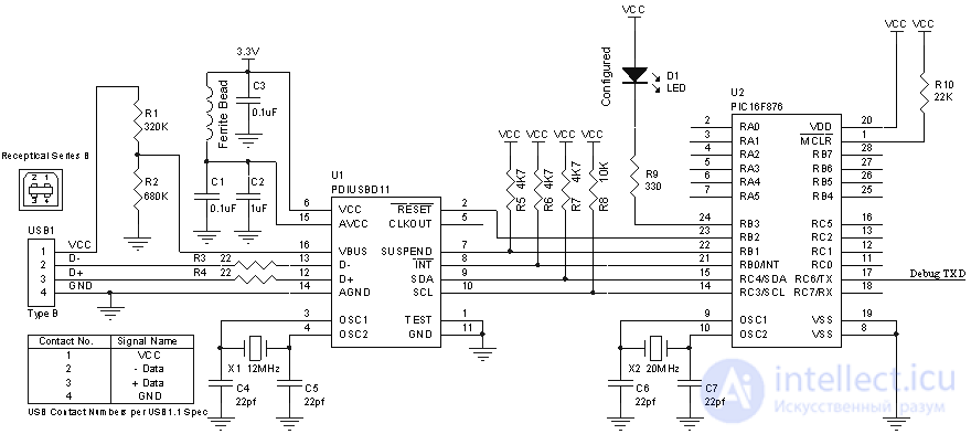
Schematic of the required hardware is shown in the figure above. The example goes through enumeration and allows you to read an analog voltage from five multiplexed ADC inputs of the PIC16F876 microcontroller. The code is compatible with the PIC16F877, which allows a maximum of 8 analog channels. An LED connected to port pin RB3 lights up when the device is configured. The 3.3V regulator is not shown, but it is required for the PDIUSBD11. If you run this example circuit from an external power supply, you can use an ordinary 78L033 3.3V regulator; however, if you want to run the device as a Bus Powered USB device, you need a low-dropout regulator.
Debugging can be done by connecting TXD (pin 17) to an RS-232 driver and connecting to a computer at 115,200 baud. The printf statements have been added to display the enumeration process.
The code is written in C and compiled with the Hi-Tech PICC Compiler. A 30-day PICC demo version (7.86 PL4) of the compiler is available for download. The compiled HEX file is included in the archive. It is compiled for use with ICD (or without it).
#include < pic.h >
#include < stdio.h >
#include < string.h >
#include "usbfull.h"
const USB_DEVICE_DESCRIPTOR DeviceDescriptor =
{
    sizeof(USB_DEVICE_DESCRIPTOR), /* bLength */
    TYPE_DEVICE_DESCRIPTOR,        /* bDescriptorType */
    0x0110,                        /* bcdUSB USB Version 1.1 */
    0,                             /* bDeviceClass */
    0,                             /* bDeviceSubclass */
    0,                             /* bDeviceProtocol */
    8,                             /* bMaxPacketSize 8 Bytes */
    0x04B4,                        /* idVendor (Cypress Semi) */
    0x0002,                        /* idProduct (USB Thermometer Example) */
    0x0000,                        /* bcdDevice */
    1,                             /* iManufacturer String Index */
    0,                             /* iProduct String Index */
    0,                             /* iSerialNumber String Index */
    1                              /* bNumberConfigurations */
};
All the structures are defined in the header file (a file with the *.h extension). We derived this example from the Cypress example, the USB thermometer, which you can use together with the USB Driver for the Cypress USB Starter Kit. A new generic driver has been written to support this and other examples that may also appear soon. Only one string is provided, to show the manufacturer. This illustrates how to implement string descriptors without overflowing the device's entire code memory. A description of the device descriptor and its fields can be found here.
const USB_CONFIG_DATA ConfigurationDescriptor =
{
    {                              /* configuration descriptor */
    sizeof(USB_CONFIGURATION_DESCRIPTOR), /* bLength */
    TYPE_CONFIGURATION_DESCRIPTOR, /* bDescriptorType */
    sizeof(USB_CONFIG_DATA),       /* wTotalLength */
    1,                             /* bNumInterfaces */
    1,                             /* bConfigurationValue */
    0,                             /* iConfiguration String Index */
    0x80,                          /* bmAttributes Bus Powered, No Remote Wakeup */
    0x32                           /* bMaxPower, 100mA */
    },
    {                              /* interface descriptor */
    sizeof(USB_INTERFACE_DESCRIPTOR), /* bLength */
    TYPE_INTERFACE_DESCRIPTOR,     /* bDescriptorType */
    0,                             /* bInterface Number */
    0,                             /* bAlternateSetting */
    2,                             /* bNumEndpoints */
    0xFF,                          /* bInterfaceClass (Vendor specific) */
    0xFF,                          /* bInterfaceSubClass */
    0xFF,                          /* bInterfaceProtocol */
    0                              /* iInterface String Index */
    },
    {                              /* endpoint descriptor */
    sizeof(USB_ENDPOINT_DESCRIPTOR), /* bLength */
    TYPE_ENDPOINT_DESCRIPTOR,      /* bDescriptorType */
    0x01,                          /* bEndpoint Address EP1 OUT */
    0x02,                          /* bmAttributes - Interrupt */
    0x0008,                        /* wMaxPacketSize */
    0x00                           /* bInterval */
    },
    {                              /* endpoint descriptor */
    sizeof(USB_ENDPOINT_DESCRIPTOR), /* bLength */
    TYPE_ENDPOINT_DESCRIPTOR,      /* bDescriptorType */
    0x81,                          /* bEndpoint Address EP1 IN */
    0x02,                          /* bmAttributes - Interrupt */
    0x0008,                        /* wMaxPacketSize */
    0x00                           /* bInterval */
    }
};
The description of the configuration descriptor and its fields can be found above. We made 2 endpoint descriptors in addition to the default channel. Endpoint EP1 OUT is a Bulk OUT endpoint with a maximum of 8 bytes, and endpoint EP1 IN is a Bulk IN endpoint with a maximum of 8 bytes. Our example reads data from the Bulk OUT endpoint and places it into an 80-byte circular buffer. Sending an IN packet to endpoint EP1 reads 8-byte chunks of memory from this circular buffer.
LANGID_DESCRIPTOR LANGID_Descriptor =
{ /* LANGID String Descriptor Zero */
    sizeof(LANGID_DESCRIPTOR),         /* bLenght */
    TYPE_STRING_DESCRIPTOR,            /* bDescriptorType */
    0x0409                             /* LANGID US English */
};
const MANUFACTURER_DESCRIPTOR Manufacturer_Descriptor =
{ /* ManufacturerString 1 */
    sizeof(MANUFACTURER_DESCRIPTOR),                     /* bLenght */
    TYPE_STRING_DESCRIPTOR,                              /* bDescriptorType */
    "B\0e\0y\0o\0n\0d\0 \0L\0o\0g\0i\0c\0"               /* ManufacturerString in UNICODE */
};
The string descriptor with index 0 is provided to support the LANGID requirements for USB string descriptors. It indicates that all the descriptors are in American English. The Manufacturer Descriptor can be a bit of a cheat, since the size of the character array is fixed in the header and is not dynamic.
#define MAX_BUFFER_SIZE 80
bank1 unsigned char circularbuffer[MAX_BUFFER_SIZE];
unsigned char inpointer;
unsigned char outpointer;
unsigned char *pSendBuffer;
unsigned char BytesToSend;
unsigned char CtlTransferInProgress;
unsigned char DeviceAddress;
unsigned char DeviceConfigured;
#define PROGRESS_IDLE 0
#define PROGRESS_ADDRESS 3
void main (void)
{
    TRISB = 0x03;  /* Int & Suspend Inputs */
    RB3 = 1;       /* Device not configured (LED) */
    RB2 = 0;       /* Reset the PDIUSBD11 */

    InitUART();
    printf("Initialising\n\r");
    I2C_Init();
    RB2 = 1;       /* Bring the PDIUSBD11 out of reset */

    ADCON1 = 0x80; /* ADC control - all 8 channels enabled, */
                   /* upgrade support for the 16F877 */
    USB_Init();
    printf("PDIUSBD11 ready to connect\n\r");
    while(1)
    {
        if (!RB0)
        {
           D11GetIRQ(); /* If IRQ is low, the PDIUSBD11
                           has an interrupt event pending */
        }
    }
}
The main function depends on the specific example. It is responsible for initializing the I/O port inputs and outputs and for initializing the I2C interface, the ADC and the PDIUSBD11. Once everything is configured, the D11GetIRQ handler processes interrupt requests from the PDIUSBD11.
void D11GetIRQ(void)
{
        unsigned short Irq;
        unsigned char Buffer ;

        /* Read the interrupt register to determine its source */
          D11CmdDataRead(D11_READ_INTERRUPT_REGISTER, (unsigned char*)&Irq, 2);

        if (Irq) printf("Irq = 0x%X: ",Irq);
The USB_Init function initializes the PDIUSBD11. This initialization procedure is omitted from the Philips datasheet for the PDIUSBD11, but is available in the FAQ. The last command enables SoftConnect of the pull-up resistor on the D+ signal, which tells the host that a full speed USB device is being connected, and represents the appearance of the USB device on the bus.
void USB_Init(void)
{
    unsigned char Buffer ;

    /* Disable the hub function in the PDIUSBD11 */
    Buffer  = 0x00;
    D11CmdDataWrite(D11_SET_HUB_ADDRESS, Buffer, 1);

    /* Set the address to 0 (default) and enable functionality */
    Buffer  = 0x80;
      D11CmdDataWrite(D11_SET_ADDRESS_ENABLE, Buffer, 1);

    /* Enable the generic endpoints */
    Buffer  = 0x02;
      D11CmdDataWrite(D11_SET_ENDPOINT_ENABLE, Buffer, 1);

    /* Set the mode - enable SoftConnect */
    Buffer  = 0x97; /* embedded function, SoftConnect, Clk Run, No LazyClk, Remote Wakeup */
    Buffer  = 0x0B; /* CLKOut = 4MHz */
    D11CmdDataWrite(D11_SET_MODE, Buffer, 2);
}
Main() makes calls to D11GetIRQ in a loop. This function reads the PDIUSBD11 interrupt register if any interrupts are pending. In that case they are handled; otherwise the loop continues. Other USB devices may have several interrupt vectors, one assigned to each endpoint. In that case each interrupt service routine (ISR) would handle its own interrupt, which makes it possible to remove the if statements.
if (Irq & D11_INT_BUS_RESET)
{
    printf("Bus Reset\n\r");
    USB_Init();
}

if (Irq & D11_INT_EP0_OUT)
{
    printf("EP0_Out: ");
    Process_EP0_OUT_Interrupt();
}

if (Irq & D11_INT_EP0_IN)
{
    printf("EP0_In: \n\r");
    if (CtlTransferInProgress == PROGRESS_ADDRESS)
    {
        D11CmdDataWrite(D11_SET_ADDRESS_ENABLE,&DeviceAddress,1);
        D11CmdDataRead(D11_READ_LAST_TRANSACTION + D11_ENDPOINT_EP0_IN, Buffer, 1);
        CtlTransferInProgress = PROGRESS_IDLE;
    }
    else
    {
        D11CmdDataRead(D11_READ_LAST_TRANSACTION + D11_ENDPOINT_EP0_IN, Buffer, 1);
        WriteBufferToEndPoint();
    }
}
The conditional statements work downward in order of priority. The highest priority is the bus reset interrupt. It simply calls the USB_Init function, which reinitializes the USB function. The next highest priority is the default channel, based on endpoint zero - EP0 OUT and EP0 IN. Enumeration and all control requests are handled here. We call another function to handle EP0_OUT requests.
When the host makes a request and wants to receive data, the PIC16F876 will send the PDIUSBD11 chip a packet of 8 bytes. Since the USB bus is controlled by the host, the PDIUSBD11 cannot send data whenever it wants; it buffers the data and waits for an IN token to be sent by the host. When the PDIUSBD11 receives the IN token, it generates an interrupt. At this point a new data packet to send must be loaded, which is done by the auxiliary function WriteBufferToEndpoint().
The CtlTransferInProgress == PROGRESS_ADDRESS section handles setting the device address. We will discuss this later.
if (Irq & D11_INT_EP1_OUT)
{
    printf("EP1_OUT\n\r");
    D11CmdDataRead(D11_READ_LAST_TRANSACTION + D11_ENDPOINT_EP1_OUT, Buffer, 1);
    bytes = D11ReadEndpoint(D11_ENDPOINT_EP1_OUT, Buffer);
    for (count = 0; count < bytes; count++)
    {
        circularbuffer[inpointer++] = Buffer[count];
        if (inpointer >= MAX_BUFFER_SIZE)
            inpointer = 0;
    }
    loadfromcircularbuffer(); //Kick Start
}

if (Irq & D11_INT_EP1_IN)
{
    printf("EP1_IN\n\r");
    D11CmdDataRead(D11_READ_LAST_TRANSACTION + D11_ENDPOINT_EP1_IN, Buffer, 1);
    loadfromcircularbuffer();
}
Endpoints EP1 OUT and EP1 IN are implemented to read and write bulk data to and from the circular buffer. The setup allows the code to be used in conjunction with the BulkUSB example from the Windows DDK. The circular buffer is defined earlier in the code as 80 bytes, which in length occupies all of bank1 of the PIC16F876 RAM.
if (Irq & D11_INT_EP2_OUT)
{
    printf("EP2_OUT\n\r");
    D11CmdDataRead(D11_READ_LAST_TRANSACTION + D11_ENDPOINT_EP2_OUT, Buffer, 1);
    Buffer  = 0x01; /* Stall the endpoint */
    D11CmdDataWrite(D11_SET_ENDPOINT_STATUS + D11_ENDPOINT_EP2_OUT, Buffer, 1);
}

if (Irq & D11_INT_EP2_IN)
{
    printf("EP2_IN\n\r");
    D11CmdDataRead(D11_READ_LAST_TRANSACTION + D11_ENDPOINT_EP2_IN, Buffer, 1);
    Buffer  = 0x01; /* Stall the endpoint */
    D11CmdDataWrite(D11_SET_ENDPOINT_STATUS + D11_ENDPOINT_EP2_IN, Buffer, 1);
    }

if (Irq & D11_INT_EP3_OUT)
{
    printf("EP3_OUT\n\r");
    D11CmdDataRead(D11_READ_LAST_TRANSACTION + D11_ENDPOINT_EP3_OUT, Buffer, 1);
    Buffer  = 0x01; /* Stall the endpoint */
    D11CmdDataWrite(D11_SET_ENDPOINT_STATUS + D11_ENDPOINT_EP3_OUT, Buffer, 1);
}

if (Irq & D11_INT_EP3_IN)
{
    printf("EP3_IN\n\r");
    D11CmdDataRead(D11_READ_LAST_TRANSACTION + D11_ENDPOINT_EP3_IN, Buffer, 1);
    Buffer  = 0x01; /* Stall the endpoint */
    D11CmdDataWrite(D11_SET_ENDPOINT_STATUS + D11_ENDPOINT_EP3_IN, Buffer, 1);
}
Endpoints 2 and 3 are not currently used, so we stall them if any data is received. The PDIUSBD11 has a Set Endpoint Enable command, which can be used to enable or disable the generic endpoints (i.e. any endpoints other than zero, which makes up the default control channel). We can use this command to disable the generic endpoints that we do not want to use. At present the code provides a foundation for further improvement.
void Process_EP0_OUT_Interrupt(void)
{
    unsigned long a;
    unsigned char Buffer ;
    USB_SETUP_REQUEST SetupPacket;

    /* Check whether the received packet is Setup or Data, together with clearing the IRQ */
    D11CmdDataRead(D11_READ_LAST_TRANSACTION + D11_ENDPOINT_EP0_OUT, &SetupPacket, 1);

    if (SetupPacket.bmRequestType & D11_LAST_TRAN_SETUP)
    {
The first thing we must do is determine whether the packet received on EP0 Out is a data packet or a Setup Packet. A Setup Packet contains a request, such as Get Descriptor, whereas a data packet contains data for a previous request. We are lucky that most requests do not send data packets from the host to the device. The request that does so is SET_DESCRIPTOR, but it is rarely used.
        /* This is a Setup Packet - read the packet */
        D11ReadEndpoint(D11_ENDPOINT_EP0_OUT, &SetupPacket);

        /* Acknowledge the Setup Packet on endpoint EP0_OUT
           & clear the buffer */
        D11CmdDataWrite(D11_ACK_SETUP, NULL, 0);
        D11CmdDataWrite(D11_CLEAR_BUFFER, NULL, 0);
        /* Acknowledge Setup Packet on endpoint EP0_IN */
        D11CmdDataWrite(D11_ENDPOINT_EP0_IN, NULL, 0);
        D11CmdDataWrite(D11_ACK_SETUP, NULL, 0);
        /* Parsing bmRequestType */
        switch (SetupPacket.bmRequestType & 0x7F)
        {
As we saw in the description of Control Transfers, a setup packet cannot be answered with NAK or STALL. When the PDIUSBD11 chip receives a Setup packet, it flushes the EP0 IN buffer and disables the Validate Buffer and Clear Buffer commands. This guarantees that the setup packet will be acknowledged by the microcontroller, by sending the Acknowledge Setup command to both the EP0 IN and EP0 OUT endpoints, before a Validate or Clear Buffer command becomes effective. Receiving a setup packet also takes control endpoint 0 out of the STALL state if it had been stalled.
Once the packet has been read into memory and the setup packet has been acknowledged, we begin analyzing the request, starting with determining the request type. For now we are not interested in the direction of the transfer, so we mask that bit off with an AND operation. The three requests that every device must answer are Standard Device Request, Standard Interface Request and Standard Endpoint Request. We implemented our functionality (reading the ADC inputs) in a vendor request (Vendor Request) – we added a case statement to the Standard Vendor requests. If our device supports a standard USB class specification, we also need to add case statements for Class Device Request, Class Interface Request and/or Class Endpoint Request.
            case STANDARD_DEVICE_REQUEST:
                printf("Standard Device Request ");
                switch (SetupPacket.bRequest)
                {
                case GET_STATUS:
                    /* Get the device Status Request that must
                       be returned: the Remote Wakeup and Self Powered states */
                    Buffer  = 0x01;
                    Buffer  = 0x00;
                    D11WriteEndpoint(D11_ENDPOINT_EP0_IN, Buffer, 2);
                    break;
                case CLEAR_FEATURE:
                case SET_FEATURE:
                    /* We do not support DEVICE_REMOTE_WAKEUP or TEST_MODE */
                    ErrorStallControlEndPoint();
                    break;
The Get Status request is used to report the state of the device: whether it is powered from the bus or has its own power source, and whether the device supports the remote wakeup function of the host. In our device we report that the device has its own power source (self powered, it is not powered from the USB bus), and that the device does not support remote wakeup.
To Device Feature requests this device will respond that it supports neither DEVICE_REMOTE_WAKEUP nor TEST_MODE, and it will return a USB Request Error.
                case SET_ADDRESS:
                    printf("Set Address\n\r");
                    DeviceAddress = SetupPacket.wValue | 0x80;
                    D11WriteEndpoint(D11_ENDPOINT_EP0_IN, NULL, 0);
                    CtlTransferInProgress = PROGRESS_ADDRESS;
                    break;
Only the Set Address command performs its processing after the status stage. All other commands must complete their processing before the status stage. The device address is read, the constant 0x80 is ORed into it, and the result is stored in the variable DeviceAddress. The OR with 0x80 is specific to the PDIUSBD11 chip: the most significant bit of its address register specifies whether the device is enabled or not. A zero-length packet is returned to the host as the status, signaling that the command completed successfully. However, the host must send an IN token, receive the zero-length packet and issue an ACK before we can change the address. Otherwise the device might not see the IN token sent to the default address (address zero).
The completion of the status stage is signaled by an interrupt on endpoint EP0 IN. To distinguish the response to setting the address from an ordinary EP0_IN interrupt, we set the variable CtlTransferInProgress to the value PROGRESS_ADDRESS. The EP0 IN handler checks the variable CtlTransferInProgress. If it equals PROGRESS_ADDRESS, the Set Address Enable command is issued to the PDIUSBD11 and CtlTransferInProgress is set to the value PROGRESS_IDLE. The host allows the device 2 ms to change its address before it sends any other command.
                case GET_DESCRIPTOR:
                    GetDescriptor(&SetupPacket);
                    break;
                case GET_CONFIGURATION:
                    D11WriteEndpoint(D11_ENDPOINT_EP0_IN, &DeviceConfigured, 1);
                    break;
                case SET_CONFIGURATION:
                    printf("Set Configuration\n\r");
                    DeviceConfigured = SetupPacket.wValue & 0xFF;
                    D11WriteEndpoint(D11_ENDPOINT_EP0_IN, NULL, 0);
                    if (DeviceConfigured)
                    {
                        RB3 = 0;
                        printf("\n\r *** Device Configured *** \n\r");
                    }
                    else
                    {
                        RB3 = 1; /* the device is not configured */
                        printf("\n\r ** Device Not Configured *** \n\r");
                    }
                    break;
                //case SET_DESCRIPTOR:
                default:
                    /* not supported - request error - Stall */
                    ErrorStallControlEndPoint();
                    break;
                }
                break;
The Get Configuration and Set Configuration requests are used to "enable" the USB device, which allows data to be transferred to endpoints other than endpoint 0. Set Configuration must be issued with the wValue field equal to the corresponding value of the bConfigurationValue field of the configuration you want to enable. In our case there is only one configuration – configuration 1. A zero configuration value means that the device is not configured, and a nonzero value means that the device is configured. The code does not fully validate the configuration value; it simply copies the value into a local variable for storage – DeviceConfigured. If the wValue field does not match the bConfigurationValue field of a configuration, a USB Request Error must be returned.
        case STANDARD_INTERFACE_REQUEST:
            printf("Standard Interface Request\n\r");
            switch (SetupPacket.bRequest)
            {
            case GET_STATUS:
                /* get the Status Request to return for the interface */
                /* zeros (reserved for future use) */
                Buffer  = 0x00;
                Buffer  = 0x00;
                D11WriteEndpoint(D11_ENDPOINT_EP0_IN, Buffer, 2);
продолжение следует...
Часть 1 All About USB: USB Interface Programming and Working with USB Peripherals
Часть 2 Communication Method in the USB Specification - All About USB:
Часть 3 Chapter 6: USB Requests - All About USB: USB Interface
Часть 4 Terms - All About USB: USB Interface Programming and Working

Comments