
Lecture
Это продолжение увлекательной статьи про usb.
...
the so-called token, is generated by the host to describe what will follow, whether it will be a read or a write transaction, and what the device address and specific endpoint are. The next packet is usually a data packet carrying the payload, followed by a handshaking packet reporting that the data or token was received successfully, or that the endpoint is stalled or unavailable to accept data.
Common USB Packet Fields
Data on the USB bus is transmitted in the following order: the LSB (Least Significant Bit) goes first. USB packets consist of the following fields:
All packets must begin with a synchronization field (sync). The sync field is 8 bits long at low speed and full speed or 32 bits at high speed, and is used to synchronize the receiver clock with the transmitter clock. The last 2 bits indicate where the PID field begins.
PID stands for Packet ID. This field is used to identify the type of packet being sent. The following table shows the possible values of this field.
| Group | PID Value | Packet Identifier |
| Token | 0001 | OUT Token |
| 1001 | IN Token | |
| 0101 | SOF Token | |
| 1101 | SETUP Token | |
| Data | 0011 | DATA0 |
| 1011 | DATA1 | |
| 0111 | DATA2 | |
| 1111 | MDATA | |
| Handshake | 0010 | ACK Handshake |
| 1010 | NAK Handshake | |
| 1110 | STALL Handshake | |
| 0110 | NYET (No Response Yet) | |
| Special | 1100 | PREamble |
| 1100 | ERR | |
| 1000 | Split | |
| 0100 | Ping |
The PID here has 4 bits, but to ensure it is received correctly, the 4 bits are complemented and repeated, resulting in an 8-bit PID. The resulting format is shown below:
| PID0 | PID1 | PID2 | PID3 | nPID0 | nPID1 | nPID2 | nPID3 |
The address field specifies which USB device the packet is intended for. The address is 7 bits long, which allows addressing up to 127 simultaneously supported devices. Address 0 is not valid for normal use; it is reserved for devices that have not yet been assigned an address. Any device that has not been assigned an address must respond to packets with address 0.
The endpoint field is composed of 4 bits, allowing 16 possible endpoints. However, low speed devices can have only 2 additional endpoints beyond the default channel (4 endpoints maximum).
Cyclic Redundancy Checks are performed on the data within the packet payload. All token packets have a 5-bit CRC, while data packets have a 16-bit CRC.
End of packet. It is signaled by a Single Ended Zero (SE0) for approximately 2 bits, followed by a J state lasting 1 bit.
USB Packet Types
USB has 4 different packet types. Token packets indicate the type of the subsequent transaction, data packets carry the payload, handshake packets are used to acknowledge data or report errors, and start of frame (SOF) packets indicate the beginning of a new frame.
There are 3 types of token packets:
In – informs the USB device that the host wants to read information.
Out - informs the USB device that the host wants to send information.
Setup – used to begin control transfers.
Token packets must conform to the following format:
| Sync | PID | ADDR | ENDP | CRC5 | EOP |
There are 2 types of data packets, each of which can carry up to 1024 bytes of data.
Data0
Data1
High Speed mode defines two other data PIDs - DATA2 and MDATA.
Data packets have the following format:
| Sync | PID | Data | CRC16 | EOP |
The maximum payload size for low-speed devices is 8 bytes. The maximum payload size for full-speed devices is 1023 bytes. The maximum payload size for high-speed devices is 1024 bytes. Data must be sent in units of bytes.
There are 3 types of handshake packets, which consist simply of a PID
ACK – acknowledgment that the packet was received successfully. NAK – a report that the device is temporarily unable to send or receive data. It is also used in interrupt transactions to inform the host that there is no data to transmit. STALL – the device is in a state that requires intervention from the host.
Handshake packets have the following format:
| Sync | PID | EOP |
The SOF packet consists of an 11-bit frame number, sent by the host every 1ms ± 500ns at full speed or every 125 µs ± 0.0625 µs at high speed.
| Sync | PID | Frame Number | CRC5 | EOP |
The USB specification offers the developer several device options depending on the required data rate. These are Low Speed (physical rate 1.5 Mbit/s ± 1.5%), Full Speed (12 Mbit/s ± 0.25%), High Speed (480 Mbit/s ± 0.05%), SuperSpeed (5 Gbit/s ± 0.06%), and SuperSpeed+ (10 Gbit/s). Low-, Full- and High-Speed devices use a single differential half-duplex communication line for data exchange, while SuperSpeed uses several. The exchange protocols are identical.
USB is a network with one master (the host) and an arbitrary number of slave devices. The network topology is an active tree. "Active" means that at each node of the tree there is a special device, a concentrator (hub). The hub handles electrical matching of the cables, packet routing, detection of device connection/disconnection, and other functions. All connections in the network are electrically and protocol-wise identical.
USB allows "hot" connection and disconnection of individual devices or network segments. "Hot" means that network operation is not disrupted, and the master is able to detect a change in the network configuration automatically, in real time. Since the whole network is powered by the master, automatic control of the network's power supply is supported: a device reports its needs to the master, and the master can forbid the device to operate if the power capabilities of the network might be exceeded.

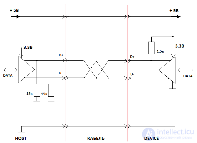
Circuitry of USB Full and High Speed ports. A Low Speed device differs in that the 1.5k resistor is connected to D− instead of D+.
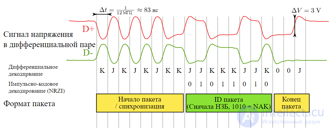
Oscillogram of a NACK packet for a Full Speed device
A simplified electrical diagram of a USB connection is shown in the figure. When nothing is connected to the host, both signal lines D+ and D− are pulled to the power ground by 15 kOhm resistors. When a device is connected, one of the lines is pulled up to +3.3 V through a 1.5 kOhm resistor. Low Speed devices pull up the D− line, and Full Speed devices pull up D+. In this way the host detects the fact of connection and the type of the connected device. High Speed devices operate as Full Speed at the moment of connection, switching to high-speed mode after an exchange of "business cards".
The state of the differential pair determined by the pull-up resistors is called Idle in the specification. The same state with the driver enabled is denoted by the letter J. The opposite state is denoted by the letter K. Shorting both lines to ground is called Single Ended 0, abbreviated SE0; shorting to the positive supply is SE1.
Data is encoded using the NRZI (Non-return-to-zero inverted) method. In this method, each zero bit of the input data corresponds to a change of state of the differential pair (J→K or K→J), while a one produces no change. To avoid loss of synchronization on long runs of ones, bit stuffing is used, that is, a zero is forcibly inserted into the data stream after every 6 consecutive ones.
A bus SE0 state lasting longer than 10 ms is interpreted by the device as a Reset and requires the device to reinitialize its USB stack. An Idle state lasting more than 3 ms in a row is interpreted by the device as a bus stop (Suspend) and formally requires the device to limit its own power consumption from the USB bus. Exit from Suspend occurs either when host activity resumes, or the device may, if necessary, send a special Resume signal. The Resume signal consists of a K state lasting several milliseconds, terminated by the sequence SE0, SE0, J, where each state lasts one bit interval according to the speed mode of the device.
Exchange takes place in short packets. Each packet begins with a Start of Packet sequence, which for Low and Full Speed is KJKJKJKK. Next always comes a special packet identifier, the PID (Packet IDentifier), which indicates the packet type. There are 16 different packet types in total, so the PID is 4 bits wide. However, for reliability the value of this field is duplicated in inverted form, so the length of the PID field in the packet is 8 bits. The packet ends with an End of Packet sequence: SE0, SE0, J. The minimum inter-packet interval is ~0.1 µs (for Full Speed).
Depending on the packet type, a number of other fields with packet parameters and/or data may be present between the PID and the EoP. All of these fields (including the PID) are transmitted least significant bit first (LSB first).
The USB packet types are presented in the table:
| Type | PID value (MSB first) | Transmitted byte (LSB first) | Name | Description |
|---|---|---|---|---|
| Reserved | 0000 | 0000 1111 | ||
| Token | 0001 | 1000 0111 | OUT | The host notifies the device that the next packet will contain data from the host to the device |
| 1001 | 1001 0110 | IN | The host notifies the device that it is ready to receive a data packet from the device | |
| 0101 | 1010 0101 | SOF | A packet marking the start of a time frame or microframe. | |
| 1101 | 1011 0100 | SETUP | The host notifies the device that the next packet will contain configuration data from the host to the device | |
| 1000 | 0001 1110 | SPLIT | USB High Speed split transaction | |
| 0100 | 0010 1101 | PING | Checks whether the device is able to receive data (USB High Speed) | |
| Special | 1100 | 0011 1100 | PRE | Notifies the hub that the next transaction will be carried out in Low Speed mode |
| Handshake | ERR | Split transaction error (USB High Speed) | ||
| 0010 | 0100 1011 | ACK | Acknowledgment of receipt of a data packet | |
| 1010 | 0101 1010 | NACK | Not ready to service the previous packet; the packet is ignored | |
| 0110 | 0110 1001 | NYET | Data is not ready yet (USB High Speed) | |
| 1110 | 0111 1000 | STALL | The previous packet addressed a nonexistent or disabled function | |
| Data | 0011 | 1100 0011 | DATA0 | Even data packet |
| 1011 | 1101 0010 | DATA1 | Odd data packet | |
| 0111 | 1110 0001 | DATA2 | Data packet for high-speed isochronous transfer (USB High Speed) | |
| 1111 | 1111 0000 | MDATA | Data packet for high-speed isochronous transfer (USB High Speed) |
IN, OUT and SETUP packets are the headers of a multi-packet data exchange transaction. They contain the address of the device and the number of the endpoint within that device with which data will be exchanged in this transaction. Packet integrity is guaranteed by the CRC5 field.
DATA packets contain a data field and a CRC16 data integrity field. The standard limits the maximum permitted data length: 8 bytes for unconfigured devices, 64 bytes for Low Speed devices, 1023 bytes for Full Speed devices and 1024 bytes for High Speed devices. A device may set its own maximum data length that is smaller than the permitted one. The host is required to support the maximum permitted data length. In normal exchange, data packets alternate as "even-odd".
ACK, NACK and STALL packets complete a transaction, reporting whether the current transaction succeeded. They contain no additional fields.
USB is a network, that is, several devices can be connected to one host. Each device is assigned a unique address during initial configuration at the moment of connection. The address is 7 bits wide, and the zero value is reserved, so up to 127 devices can be connected to one host. Only the packets that begin a transaction (IN, OUT, SETUP) contain the address field.
Besides addressing physically connected devices, USB offers logical addressing inside a device. Logical addressing makes it possible to separate data streams for different functions within one device. For example, a keyboard with a touchpad may have one data channel for key presses and another for touchpad data. In the TCP/IP stack there is a direct analogy to the endpoint: ports.
The "endpoint" field is 4 bits wide, so up to 16 endpoints are possible. Each endpoint can work independently as a receiving and as a transmitting endpoint, so they are sometimes counted as 32. The "endpoint" field is part of addressing in the USB network and is contained only in the same packets that carry the address (IN, OUT, SETUP). At the moment of connection, as part of initial configuration, the device is required to pass the host information about the endpoints in use and their purpose. This information must be consistent with the corresponding data channels of the device's software driver on the host. An access to an unused endpoint causes a STALL response. SETUP packets can arrive only at endpoint zero.
The USB specification includes the concepts of time frames and microframes. For Low Speed devices, the host transmits a Keep Alive signal every millisecond, consisting of a sequence of End of Packet signals. For Full Speed devices, the host transmits a special SOF (Start of Frame) packet every millisecond, marking the beginning of the next frame. For High Speed, this packet is transmitted every 125 µs; such a period is called a microframe. The USB specification requires transactions and packets to be scheduled so that the periodicity of SOF delivery is not violated.
Data is exchanged in so-called transactions, which are indivisible sequences of several packets. The exchange is always initiated by the host. It sends a short packet (token) announcing the start of a new transaction. In this token packet the host specifies the direction of the transaction (IN or OUT), the device address and the endpoint number. For example, an OUT token means that the token will be immediately followed by a data packet from the host to the device (DATA0 or DATA1). A transaction may contain several data packets if each of them has the maximum data length allowed for that device. The end of the data transfer is recognized by a packet length that is not equal to the maximum. As soon as a shortened packet arrives, the device immediately sends a response packet, a handshake, for example ACK (everything was received successfully), NACK (unable to receive: for example, the input buffer is full) or STALL (the data is addressed to a disabled endpoint). All packets in a transaction are transmitted almost back to back, and the maximum pause between packets must not exceed about 1 µs (for Full Speed); otherwise the transaction is considered erroneous.
Data transfer from the device to the host works similarly. The host initiates the transfer with an IN token. If the device has no data ready to send, it responds with NACK and the transaction ends. If data is ready, the device starts transmitting DATA0/DATA1 packets. The end of the transfer is determined in the same way: a data packet of less than full length. Having received a short packet, the host responds to the device with an ACK handshake packet.
A transaction with a SETUP token is completely analogous to an OUT transaction; the only difference is in how the device interprets the data: these are connection parameters that control the operation of the device's USB stack.
The USB specification provides several methods of data exchange. One of the methods must be assigned to each enabled endpoint. Control, Interrupt and Bulk use the exchange protocol with acknowledgements described just above. The bulk method allows the host to exchange data with the device freely, at its own discretion. The control method is similar to bulk, but exchanges with the device only special data that controls the operation of the USB protocol in accordance with the specification (within SETUP-type transactions). Because peripheral devices cannot initiate an exchange, the interrupt method was devised for sending data that suddenly appears on the device; it allows the device to be polled with a specified period. The interrupt method is widely used for polling keyboards and mice. The isochronous method stands apart: it allows part of the USB bus bandwidth to be reserved for data such as audio or video. Isochronous does not support transfer integrity control (ACK and NACK packets are not sent), which means that no retries are provided in case of errors: incorrectly received data is lost.
At the moment of connection, the host requests from the device a number of standardized items of information (descriptors), on the basis of which it decides how to work with this device. The descriptors contain information about the manufacturer and the type of the device, on the basis of which the host selects a software driver. The descriptor tables and the purpose of their fields are described in detail in Chapter 9 of the USB specification.
After that, the host changes the speed (if the device is High Speed) and assigns an address to the device.
To debug protocols and verify compliance with the standard, device developers can use various tools that make it possible to observe exchange processes on the bus[44][45]. These tools may be purely software, extracting bus events from the computer's USB drivers. However, such tools do not show signals on the bus that are handled by hardware or that are erroneous. For comprehensive independent verification, specialized hardware scanners and protocol analyzers are used. The USB consortium recommends using a hardware analyzer for passing certification and when preparing devices for serial production.
Formally, to obtain the right to place USB logos on a product, the product must be certified for compliance with the standard. The USB-IF organization offers certification services for USB devices and also maintains a list of third-party certification laboratories[46].
USB functions
When we picture a USB device, we think of it as a USB peripheral, but "USB device" could mean a USB transceiver used in a host or peripheral, a USB hub or a host controller chip, or a USB peripheral. The standard therefore refers to USB functions, which can be seen as USB devices that provide a particular functionality, such as a printer, a Zip drive, a scanner, a modem or other peripherals.
By now we should already know a number of the concepts that make up a USB packet. No? Have you already forgotten how many bits are in the PID field? Do not be too concerned about it. Fortunately, in most USB functions the low levels of the USB protocol (up to the transaction layer, which we will cover in the next chapter) are already handled in silicon (in dedicated chips). We look at information about the low layers of the USB protocol because most USB function controllers report errors such as PID Encoding Error. Without a brief look at the low level, one might ask what a PID Encoding Error means. If you guessed that the last four bits of the PID did not match the inversion of the first four bits, you would be right.
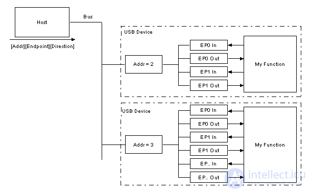
Most functions have a series of buffers, usually 8 bytes long. Each buffer belongs to an endpoint: EP0 IN, EP0 OUT, and so on. For example, the host sends a device descriptor request. The function reads the setup packet in hardware and determines from the address field whether the packet is intended for it, and if so, it copies the payload of the following data packet into the corresponding endpoint buffer, specified by the value in the endpoint field of the setup token. A handshake packet is also sent to acknowledge receipt of the byte, and an internal interrupt is generated in the microcontroller for the corresponding endpoint, indicating that a packet has been received. All of this is usually done in "hardware" (the circuitry of the USB device controller chip).
The software (the microcontroller firmware) receives the interrupt, in which it must read the contents of the endpoint buffer and parse the device descriptor request.
Endpoints
Endpoints can be described as sources or sinks of data. Because the bus is host-oriented, endpoints are located at the end of the communication channel, on the USB function. For example, at the software level your device driver may send a packet to endpoint EP1 of the device. Because the data comes from the host, it goes into the OUT buffer of EP1. Your firmware can now read this data at its leisure. If the device wants to send data back, the function cannot simply write it onto the bus, because the bus is entirely controlled by the host. So the firmware places the data in the EP1 IN buffer, and the data stays in the buffer until the host sends an IN packet requesting the endpoint's data. Endpoints can also be viewed as the interface between the hardware of the device function and the firmware running on the device function.
All devices must support endpoint 0. This is the endpoint that receives all control and status requests during enumeration and for as long as the device remains operational on the bus.
Pipes
When a device sends and receives data through several endpoints, the client software passes data through pipes. A pipe is a logical connection between the host and an endpoint (or endpoints). Pipes also have a set of parameters: the transfer type (Control, Bulk, Iso or Interrupt), the direction of data flow, and the maximum packet/buffer sizes. For example, the default pipe is a bidirectional pipe made up of IN endpoint 0 and OUT endpoint 0 with the control transfer type.
USB defines two types of pipes
The USB standard defines 4 types of endpoints/transfers:
Control transfers
Control transfers are typically used for commands and status operations. The basic setup of a USB device, including all enumeration functions, is done using control transfers. These are usually quick, randomly timed packets initiated by the host, which have best-effort delivery priority. The maximum allowed payload length (payload, or packet size) of a control transfer is 8, 16, 32 or 64 bytes for full-speed USB devices; for high-speed devices this size is 64 bytes, and for low-speed devices it is 8 bytes (only 8 bytes, with no other options).
Control transfers can have up to 3 stages.
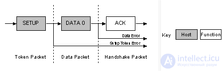
The data stage has two different scenarios, depending on the direction of the data transfer.
IN scenario: when the host is ready to receive control data, it issues an IN token. If the function receives an IN token with an error, for example the PID does not match the inverted PID bits, it ignores the packet. If the token is received successfully, the device can respond with a DATA packet containing the control data to be sent, with a stall packet indicating an endpoint error, or with a NAK packet showing the host that the endpoint is working but has no data to send yet.
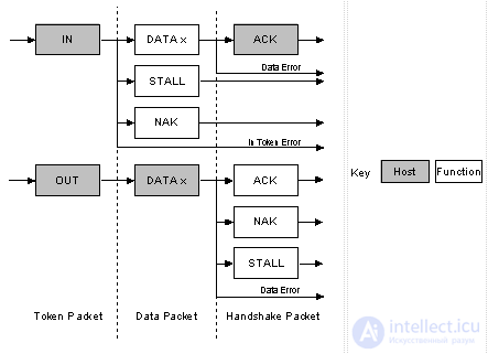
OUT scenario: when the host needs to send the device a control data packet, it issues an OUT token, followed by a packet containing the control data as its payload. If any part, either the OUT token or the data packet, is erroneous, the function ignores the packet. If the endpoint buffer is empty, the function fills the buffer with the data and sends an ACK, informing the host that the data was received successfully. If the endpoint buffer is not empty because the previous packet is still being processed, the function responds with NAK. However, if the endpoint had an error and its halt bit was set, it returns STALL.
The status stage also has two different scenarios, depending on the direction of the data transfer.
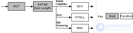
IN scenario: if the host sent IN token(s) during the data stage to receive data, the host must acknowledge successful receipt of the data. It does this by sending an OUT token followed by a zero-length data packet. The function can now report its status in the handshaking stage. ACK indicates that the function has completed the command and is ready to receive the next command. If an error occurred while processing this command, the function issues STALL. However, if command processing is still in progress, the function issues NAK, telling the host to repeat the status stage later.
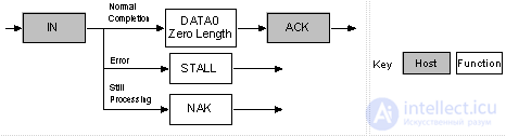
OUT scenario: if the host sent OUT token(s) during the data stage to send data, the function acknowledges successful receipt of the data by sending a zero-length packet in response to an IN token. However, if an error occurred, the function must issue STALL, or if the data is still being processed, it must issue NAK, telling the host to repeat the status phase later.
Control transfers: overview
Now, how does all this fit together? For example, the host wants to request a device descriptor during enumeration. The packets that are sent will be as follows.
The host sends a Setup token, telling the function that the next packet will be a Setup packet. The address field will contain the address of the device from which the host is requesting the descriptor. The endpoint number must be 0, which indicates the default pipe. Then the host will send a DATA0 packet. It will contain 8 bytes of payload, which will be a Device Descriptor Request, described in Chapter 9 of the USB specification. The USB function acknowledges that the setup packet was read correctly, without errors. If the packet is received with an error, the device simply ignores that packet. The host must resend the packet later, after a short delay.
1. Setup token |
Sync | PID | ADDR | ENDP | CRC5 | EOP | Address and endpoint number |
| 2. Data0 packet | Sync | PID | Data0 | CRC16 | EOP | Device Descriptor Request | |
| 3. Ack Handshake | Sync | PID | EOP | The device acknowledges the Setup packet |
The three packets above make up the first USB transaction. Now the USB device will decode the 8 received bytes and determine from them that this is a device descriptor request. After that, the device will attempt to send the Device Descriptor, which will happen in the next USB transaction.
1. In token |
Sync | PID | ADDR | ENDP | CRC5 | EOP | Address and endpoint number |
| 2. Data1 packet | Sync | PID | Data1 | CRC16 | EOP | First 8 bytes of the device descriptor | |
| 3. Ack Handshake | Sync | PID | EOP | The host acknowledges the packet |
| 1. In token | Sync | PID | ADDR | ENDP | CRC5 | EOP | Address and endpoint number |
| 2. Data0 packet | Sync | PID | Data0 | CRC16 | EOP | Last 4 bytes + Padding | |
| 3. Ack Handshake | Sync | PID | EOP | The host acknowledges the packet |
In this case we assume that the maximum payload size is 8 bytes. The host sends an IN token, thereby telling the device that it can now send data for this endpoint. Because the maximum packet size is 8 bytes, we must split the 12 bytes of the device descriptor into pieces for sending. Each piece must be 8 bytes in size, except for the last transaction. The host acknowledges each packet that we send to it.
Once the device descriptor has been sent, the status transaction begins. If the transactions were successful, the host sends a zero-length packet, showing that the whole transaction was successful. The function responds to this with a zero-length packet indicating its status.
1. Out token |
Sync | PID | ADDR | ENDP | CRC5 | EOP | Address and endpoint number |
| 2. Data1 packet | Sync | PID | Data1 | CRC16 | EOP | Zero-length packet | |
| 3. Ack Handshake | Sync | PID | EOP | The device acknowledges the entire transaction |
Interrupt transfers
Anyone who has dealt with interrupt requests on microcontrollers knows that interrupts are generated by the device (inside the microcontroller). Under USB control, however, if a device requires the host's attention, it must wait until the host polls it before it can signal that it needs an urgent data exchange! Interrupt transfers have the following characteristics:
Interrupt transfers are usually non-periodic, when a USB device "initiates" communication that requires a limited waiting time. An "interrupt" request is queued by the USB device until the computer polls the USB device to obtain the data.
Maximum payload for low-speed devices is 8 bytes.
Maximum payload for full-speed devices is 64 bytes.
Maximum payload for high-speed devices is 1024 bytes.
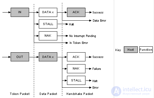
The diagram shows the format of Interrupt IN and Interrupt OUT transactions.
Interrupt IN: the host periodically polls the interrupt endpoint. The polling rate is specified in the endpoint descriptor, which we will look at later. Each poll is accompanied by the host sending an IN token. If the IN token is corrupted, the function ignores the packet and continues monitoring the bus, waiting for new tokens.
If an interrupt has been queued by the USB device, the function will send a data packet containing the data corresponding to the interrupt when it receives the IN token. After successful receipt by the host, the host returns ACK. However, if the data was corrupted, the host does not return a status. If the interrupt condition was not present when the host polled the interrupt endpoint with an IN token, the function answers with a NAK status. If an error has occurred on this endpoint, STALL is sent in response to the IN token.
Interrupt OUT: when the host wants to send interrupt data to the device, it issues an OUT token followed by a data packet containing the interrupt data. If any part, either the OUT token or the data packet, is erroneous, the function ignores the packet. If the function's endpoint buffer was empty and the function has written the data to the endpoint buffer, it issues ACK, informing the host that the data was received successfully. If the endpoint buffer is not empty (the previous packet is still being processed), the function issues NAK. However, if an error occurred on the endpoint and its halt bit was set, the function issues STALL.
Isochronous transfers
Isochronous transfers occur periodically and continuously over a long time. They usually carry time-bound information (sensitive to delivery time), such as audio or video streams. If a delay or retransmission of data occurs in an audio stream, you will end up with distorted sound. An additional problem is that audio synchronization may be lost. However, dropped packets or frames can happen again and again, and this will be less noticeable to the listener. Isochronous transfers provide:
For an isochronous endpoint, the maximum data payload size is specified in the endpoint descriptor. This size can be up to 1023 bytes for full speed and up to 1024 bytes for high speed. Because the maximum payload size affects the bus bandwidth requirement, it should be chosen carefully. If you use a large payload, it may be a good choice to define a series of alternative interfaces with different isochronous payload sizes. If during enumeration the host cannot grant your isochronous endpoint the requested bandwidth because of bandwidth limitations, it will still have other bandwidth options instead of failing completely. The data sent through an isochronous endpoint may be smaller than the previously agreed size, and may vary in length from transaction to transaction.
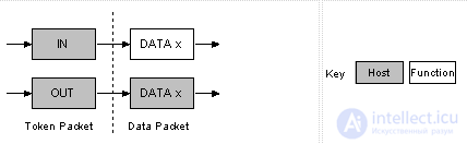
The diagram shows the format of isochronous IN and OUT transactions. Isochronous transactions have no handshaking stage and cannot report errors or STALL/HALT events.
Bulk Transfers
Bulk transfers can be used for large amounts of data that are not time-critical. Examples are a print job sent to a printer or an image generated by a scanner. Bulk transfers provide payload error correction through the CRC16 field, as well as error detection and retransmission mechanisms that guarantee that the transmitted or received data is error-free.
Bulk transfers use whatever bus bandwidth remains after all other transactions have been allocated. If the bus is busy with isochronous and/or interrupt data, bulk data may move across the bus slowly. Therefore, bulk transfers should be used only for intensive communication where delivery time is not guaranteed. Characteristics of bulk transfers:
Bulk transfers are supported only by full-speed and high-speed devices. For full-speed endpoints, the maximum bulk packet size is 8, 16, 32 or 64 bytes. For high-speed endpoints, the maximum packet size can be up to 512 bytes. If the data payload is smaller than the maximum packet size, it does not have to be padded with zeros. A bulk transfer is considered complete when it has transferred the exact amount of data requested, transferred a packet smaller than the endpoint's maximum packet size, or transferred a zero-length packet.
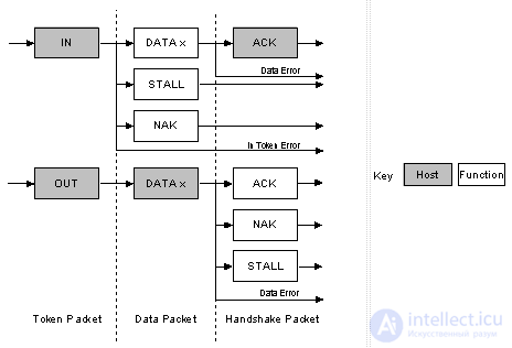
The diagram shows the format of bulk IN and bulk OUT transactions.
Bulk IN: when the host is ready to receive bulk data, it issues an IN token. If the function receives the IN token with an error, it ignores the packet. If the token is received correctly, the function can respond with a DATA packet (containing the bulk data to be sent), with a STALL packet (indicating that the endpoint has an error), or with a NAK packet (indicating that the endpoint is working but has no data to send yet).
Bulk OUT: when the host wants to send a bulk data packet to the function, it issues an OUT token followed by a data packet containing the bulk data. If any part of the OUT token or the data packet is corrupted, the function ignores the packet. If the function's endpoint buffer is empty, the function shifts the data into the endpoint buffer and issues an ACK, informing the host that the data was received successfully. If the function's endpoint buffer is not empty because the previous packet is still being processed, the function returns a NAK. However, if the endpoint is in an error state and its halt bit is set, the function returns a STALL.
Bandwidth Management
The host is responsible for managing the bus bandwidth. This happens during enumeration and when configuring isochronous and interrupt endpoints through bus operations. The specification places limits on the bus that allow no more than 90% of all frames to be allocated to periodic transfers (interrupt or isochronous) on a full-speed bus. On a high-speed bus this limit is reduced: no more than 80% of microframes can be allocated to periodic transfers.
Thus, it is clear that if you have a bus heavily loaded with periodic transfers, the remaining 10% is reserved for control transfers, and once those have been allocated (processed), bulk transfers get the remaining bandwidth.
All USB devices have a hierarchy of descriptors that describe information for the host, such as what the device is, who made it, which version of USB the device supports, the ways in which the device can be configured, the number of endpoints and their types, and so on.
The most common USB descriptors are the following:
A USB device can have only one device descriptor. The device descriptor includes information such as the USB revision the device supports, the Product ID (PID) and Vendor ID (VID) used to load the driver appropriate for the device, and the number of possible configurations of the device. The number of configurations indicates how many branches there are among the configuration descriptors.
The configuration descriptor specifies the amount of power drawn from the bus, whether the device is self powered or bus powered, and the number of interfaces the configuration has. When a device goes through enumeration, the host reads the device descriptor and decides which configuration to apply. The host can enable only one of the configurations.
For example, there might be a configuration with high power consumption from the bus and a configuration with a self-powered supply. If the device is connected to a desktop host with mains power, the driver may choose the high bus-power configuration even though the device has its own power source. When it is connected to a laptop host (running on battery), the driver may force the self-powered configuration, which will require the user to connect an external power supply for the USB device.
Configuration settings are not limited to differences in power. Each configuration can be set up for the same power but have different interfaces or sets of endpoints. Note, however, that changing the configuration requires all activity on every endpoint to stop. Although USB offers this capability, very few devices have more than 1 configuration.
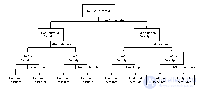
An interface descriptor can be thought of as a header or grouping of endpoints into a functional group that performs a single feature of the device. For example, you might have a multifunction fax/scanner/printer device. Interface descriptor 1 might describe the endpoints of the fax function, interface descriptor 2 might describe the scanner function, and interface descriptor 3 might describe the printer function. Unlike the configuration descriptor, there is no limit on the number of interfaces enabled at the same time. A device can have 1 or many interfaces enabled simultaneously.
Interface descriptors have a bInterfaceNumber field, which indicates the interface number, and a bAlternateSetting field, which allows the interface to change its settings on the fly. For example, suppose you have a device with two interfaces: interface 1 and interface 2. Interface 1 has its bInterfaceNumber field set to 0, showing that it is the first interface descriptor, and its bAlternativeSetting field set to 0. Interface 2 has its bInterfaceNumber field set to 1, showing that it is the second interface, and its bAlternativeSetting field set to 0 (the default value). We could add another descriptor here whose bInterfaceNumber field is also set to 1 (showing that it is the second interface), but this time with the bAlternativeSetting field set to 1, showing that the interface descriptor can have an alternative setting, taken from another descriptor of interface 2.
When this configuration is enabled, the first two interface descriptors, whose bAlternativeSettings field equals 0, are used. However, during operation the host can send a SetInterface request addressed to interface number 1 (the second interface) with alternative setting 1, which enables a different interface descriptor.
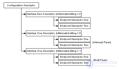
This is an advantage of using two configurations: we can transfer data through interface 0 while changing the settings of the endpoint associated with interface 1, without disturbing the operation of interface 0.
Each endpoint descriptor is used to specify the transfer type, direction, polling interval and maximum packet size for each endpoint. Endpoint 0 is always implied to be the default control endpoint, and therefore it has no descriptor.
Structure of USB Descriptors
All descriptors share a common format. The first byte gives the length of the descriptor in bytes, and the second byte gives the descriptor type. If the descriptor length is smaller than defined in the specification, the host computer should ignore it. If the size is larger than expected, however, the host will ignore the extra bytes and look for the next descriptor at the end of the valid returned length.
|
Offset |
Field |
Size |
Value |
Description |
|
0 |
bLength |
1 |
Number |
Size of the descriptor in bytes |
|
1 |
bDescriptionType |
1 |
Constant |
Descriptor type |
|
2 |
... |
n |
|
Start of the descriptor parameters |
Device Descriptors
The device descriptor of a USB device represents the device as a whole. Consequently, a USB device can have only one device descriptor. This descriptor gives some basic (undoubtedly important) information about the device, such as the supported USB version, the maximum packet size, the vendor and product IDs (VID and PID), and the number of possible configurations the device can have. The format of the device descriptor is shown below.
|
Offset |
Field |
Size |
Value |
Description |
|
0 |
bLength |
1 |
Number |
Size of the descriptor in bytes (18 bytes for the device descriptor) |
|
1 |
bDescriptorType |
1 |
Constant |
Type - Device Descriptor (0x01) |
|
2 |
bcdUSB |
2 |
BCD |
Number of the USB specification with which the device is compatible. |
|
4 |
bDeviceClass |
1 |
Class |
Class code (assigned by USB Org) |
|
5 |
bDeviceSubClass |
1 |
SubClass |
Subclass code (assigned by USB Org) |
|
6 |
bDeviceProtocol |
1 |
Protocol |
Protocol code (assigned by USB Org) |
|
7 |
bMaxPacketSize |
1 |
Number |
Maximum packet size for endpoint 0. Valid sizes are 8, 16, 32, 64 |
|
8 |
idVendor |
2 |
ID |
Vendor ID, VID (assigned by USB Org) |
|
10 |
idProduct |
2 |
ID |
Product ID, PID (assigned by the manufacturing organization) |
|
12 |
bcdDevice |
2 |
BCD |
Device Release Number (device version number) |
|
14 |
iManufacturer |
1 |
Index |
Index of the string describing the manufacturer |
|
15 |
iProduct |
1 |
Index |
Index of the string describing the product |
|
16 |
iSerialNumber |
1 |
Index |
Index of the string containing the serial number |
|
17 |
bNumConfigurations |
1 |
Integer |
Number of possible configurations |
Configuration Descriptors
A USB device can have several different configurations, although most devices are simple and have only one. The configuration descriptor specifies how the device is powered, its maximum power consumption, and the number of interfaces the device has. It is therefore possible for a device to have 2 configurations: one for bus power and another for power from a main (external) source. Since this is the header for the interface descriptors, it is also possible to have different configurations for different transfer modes.
Once all the configurations have been read and analyzed by the host, it sends a SetConfiguration command with a non-zero value that corresponds to the bConfigurationValue of one of the configurations. This is used to select the desired configuration.
|
Offset |
Field |
Size |
Value |
Description |
|
0 |
bLength |
1 |
Number |
Size of the descriptor in bytes |
|
1 |
bDescriptorType |
1 |
Constant |
Configuration descriptor (0x02) |
|
2 |
wTotalLength |
2 |
Number |
Total length of the returned data in bytes |
|
4 |
bNumInterfaces |
1 |
Number |
Number of interfaces |
|
5 |
bConfigurationValue |
1 |
Number |
Value used as an argument to select this configuration |
|
6 |
iConfiguration |
1 |
Index |
Index of the string descriptor describing this configuration |
|
7 |
bmAttributes |
1 |
Bit set (Bitmap) |
D7 reserved, set to 1. (USB 1.0 Bus Powered) |
|
8 |
bMaxPower |
1 |
mA |
Maximum power consumption in units of 2 mA |
продолжение следует...
Часть 1 All About USB: USB Interface Programming and Working with USB Peripherals
Часть 2 Communication Method in the USB Specification - All About USB:
Часть 3 Chapter 6: USB Requests - All About USB: USB Interface
Часть 4 Terms - All About USB: USB Interface Programming and Working

Comments