
Lecture
This article addresses the problem of controlling a two-wheeled balancing robot. The advantages and existing applications of this type of robot are investigated. A review of implemented systems, their purposes, and their features is presented. A version of the robot capable of maintaining balance in
place has been developed.
Introduction
Robotics began in the 1960s, when, owing to the rapid growth of industrial production and advances in electronics, it became possible to build an automatic machine for the needs of assembly-line production of consumer goods. Since then the use of robots has expanded considerably and gone far beyond industrial needs. With the start of the new millennium, robotics has been actively introduced into all areas of human activity, including everyday life.
A traditional robot that interacts with a person has a wide base and moves with small accelerations to avoid losing stability. The center of mass of such mobile wheeled robots is kept as close as possible to the surface over which the motion takes place, and for the sake of stability the robot
always has at least 3 points of support.
Two-wheeled balancing robots have a smaller base because they do not require static stability. The pair of wheels allows the robot to turn in place,
which gives it greater mobility. Robots of this design also have lower power consumption.
This work examines a relatively new area for mobile, inherently unstable robots – maintaining balance and moving by shifting the center of gravity. This feature makes it possible to build a mobile
two-wheeled robot capable of maintaining balance in place while simultaneously
moving its individual parts (manipulators).
Robots of this kind can be used as mobile assistants to a worker, carrying a variety of tools and capable of performing non-critical tasks under the direction of an operator using augmented-reality systems; as manually operated forklifts, for mapping premises that are hazardous to humans, for working as guards (mobile video cameras), and as wheelchairs and personal
mobility aids for humans.
Although the first two-wheeled balancing robot was built by Kazuo Yamafuji in 1986, most such robots were created between 2003 and 2012. Methods and means of controlling such two-wheeled balancing robots are extremely important for practical robotics and make it possible to build automatic control systems for any mechatronic systems on their basis.
1. Review of existing solutions
Let us consider the main design and structural-functional features, as well as the areas of application, of existing two-wheeled balancing robots.
nBot (fig. 1) uses an accelerometer to obtain the tilt angle and a gyroscope to obtain the rate of change of the tilt angle. A Wiener filter is used to combine the signals of these two sensors into one. Balancing formula: the motor is supplied with a voltage proportional to the tilt angle, the angular velocity, the chassis position, and its velocity.
Turning is achieved by adding a voltage value to one motor and subtracting it from the other. In this way, the robot can turn while keeping its
balance. Straight-line motion is achieved by adding a value to the balance angle.
JOE (fig. 2) was developed as a miniature prototype vehicle for carrying people. Stabilization uses a state-space controller that receives information from a gyroscope and motor encoders.
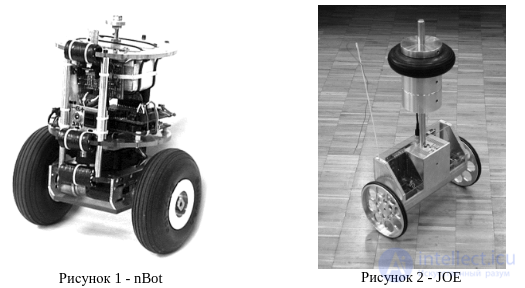
Figure 1 - nBot Figure 2 - JOE
The robot built by Peter Miller obtains the chassis position from motor encoders and the velocity value by differentiating the position value. A gyroscope and accelerometer combined by a Kalman filter make it possible to obtain an accurate velocity and tilt-angle value without loss of accuracy over time. Control is performed using a nonlinear fuzzy-logic system that distributes
control signals to the motor of each wheel.
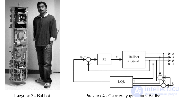
Ballbot (fig. 3) – a robot that balances on a ball. It was developed for interaction with people. The control system (fig. 4) consists of two loops: the inner one – a PI controller, the outer one – a linear-quadratic regulator.
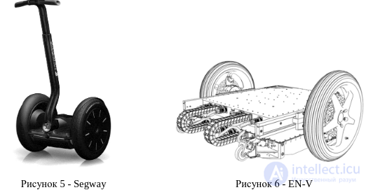
Segway (fig. 5) – a commercially available platform used for transport over relatively short distances in various fields, from tourism to police patrols. EN-V (fig. 6) – a concept two-wheeled vehicle developed by Segway together with General Motors. Unlike other unstable two-wheeled robots, control is achieved by shifting a load, which causes the center of gravity to shift relative to the wheel axis.
In most robots, the tilt angle is calculated by integrating the angular velocity obtained from the gyroscope and is corrected by successive approximation to the angle computed from the accelerometer readings. At the same time, all parameters are processed by a Kalman filter.
At the first stage, the goal of the development is an autonomous two-wheeled balancing robot with no moving parts and two degrees of freedom (fig. 7). The wheels are coaxial, and power is supplied by a battery pack. The center of gravity is located above the wheel axis. The task is to balance around the equilibrium position. Information about the position is obtained using a gyroscope and a two-axis accelerometer. Motor shaft encoders make it possible to measure the speed and direction of the robot's motion. Additional information can be obtained from a video camera mounted on the robot and tracking angular deviation from a predefined visual landmark. Control signals from the microprocessor go to the motor drivers, which then convert them into motor torques.
In addition, the robot is fitted with a center-of-gravity shifting system that converts the rotary motion of motor 1 into linear motion, by means of rack-and-pinion gear 2, of load 3, which may be the power supply (fig. 8).
Such a system can also be used to shift the center of gravity in the vertical plane. Together these means may be needed when studying the behavior
of the control system under center-of-mass shifts in different directions and in its further
improvement.
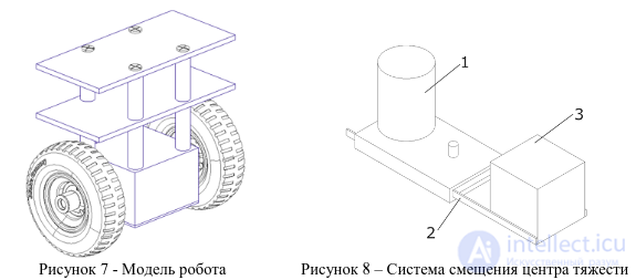
Figure 7 - Robot model Figure 8 – Center-of-gravity shifting system
This work uses an abstraction that makes it possible to simplify the real system with 5 degrees of freedom down to a system with 2 degrees (fig. 9).
This model is a cart with one degree of freedom (motion along the x axis) with a pole hinged to it that can rotate in the vertical plane. A controller can act on the cart with a force F, thereby changing its horizontal position. There is no friction in the system. The mass of the cart is  , the mass of the pole is
  , the length is
  . The variable x is the position of the cart along the x axis,
  is the deviation of the pole from the vertical position.
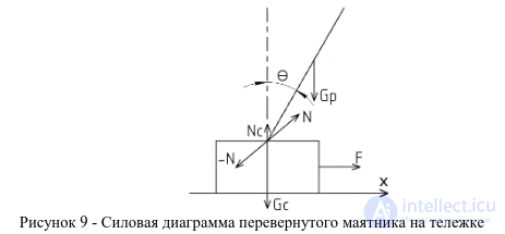
Figure 9 - Force diagram of an inverted pendulum on a cart
Dynamic equations of this system:5
Angular acceleration: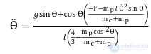
Horizontal acceleration: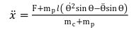
Bushings 1 are mounted on the axis of both wheels, making it possible to fix the robot in place, thereby eliminating unnecessary degrees of freedom and ensuring that the robot's tilt angle can be measured. One of the bushings, with one rotational degree of freedom, is pivotally mounted in the carriage of angle sensor 2, while the sensor's own shaft is attached to the robot's chassis by means of mount 3 (fig. 10, b).
An alternative way of measuring the tilt angle is to install video camera 2, which compares the robot's position with horizontal reference 1, where 3 is the robot's vertical axis, associated with its deviation from the equilibrium position (fig. 10, c). The experiment consists of displacing the robot from its state of equilibrium in order to
determine the quality of the control system. A variable parameter in this
configuration is also the vertical position of the robot's center of mass (fig. 10, a).
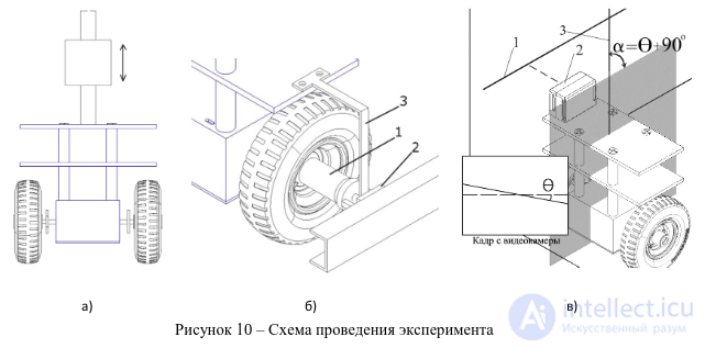
Figure 10 – Experimental setup diagram
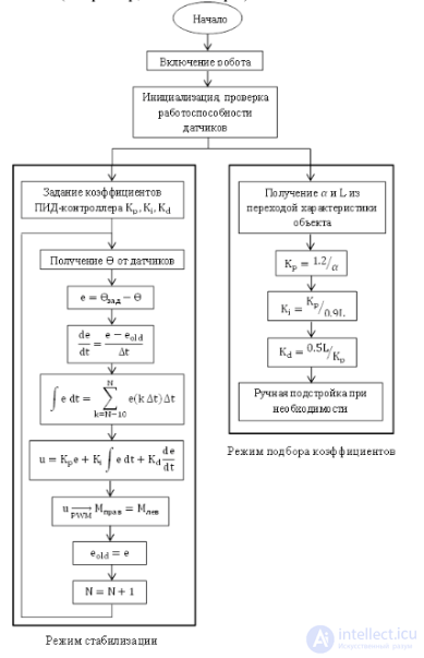
The PID controller coefficients are selected using the Ziegler-Nichols method. The variables L and α are determined from the plant's step response. The constants are set according to the formulas given above and are manually fine-tuned as needed.
Stabilization mode begins with obtaining the tilt angle θ value from the Kalman filter. The error e is found, and the integral and differential components are computed, where ∆t is the sampling interval determined by the microcontroller's performance, and k is the index of the time interval. The resulting control signal is converted by PWM and passed through the drivers to the motors, producing torques. The error values are stored in memory for use in computing the control-signal components in subsequent iterations (fig. 11).6
The article addressed the problem of controlling a two-wheeled balancing robot. The advantages of this type of robot were investigated, along with the possibility of using a controlled system for shifting the position of the center of gravity. A review of existing systems was carried out.
A version of the robot with a limited number of degrees of freedom, capable of balancing around the vertical equilibrium position, was developed.
Further work on the project involves increasing the degrees of freedom of the controlled object and making the automatic control system more sophisticated. One of the promising directions for the project's further development is seen as the task of controlled shifting of the position of the center
of mass of the controlled object.
A number of experiments must be conducted to verify the approaches that have been developed.
Setting up the experiments is a priority task for the project's near-term development. In
particular, obtaining independent objective data will support incorporating
additional sensors (such as a video camera) into the system.
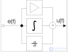
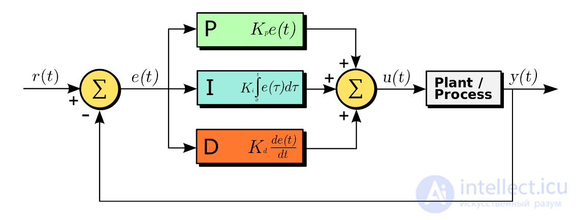
Diagram illustrating the operating principle of a PID controller. The coefficients in front of the integral and derivative terms are omitted for clarity of illustration.
A proportional-integral-derivative (PID) controller — a device in a feedback control loop. It is used in automatic control systems to shape the control signal in order to obtain the required accuracy and quality of the transient process. A PID controller produces a control signal that is the sum of three terms, the first of which is proportional to the difference between the input signal and the feedback signal (the error signal), the second — the integral of the error signal, the third — the derivative of the error signal.
If some of the components are not used, the controller is called a proportional-integral, proportional-derivative, proportional controller, and so on.
The proportional term produces an output signal that counteracts the deviation of the controlled quantity from the set value observed at the given moment. It is larger the larger this deviation is. If the input signal equals the set value, then the output is zero.
However, when using only a proportional controller, the value of the controlled quantity never stabilizes at the set value. There is a so-called static error, equal to the deviation of the controlled quantity that produces an output signal stabilizing the output quantity precisely at that value. For example, in a temperature controller the output signal (heater power) gradually decreases as the temperature approaches the setpoint, and the system stabilizes at a power equal to the heat losses. The temperature cannot reach the setpoint, since in that case the heater power would become zero and it would begin to cool.
The larger the proportionality coefficient between the input and output signal (the gain), the smaller the static error; however, if the gain is too large and there are delays (lag) in the system, self-oscillation may begin, and with a further increase in the coefficient the system may lose stability.
The integral term is proportional to the time integral of the deviation of the controlled quantity. It is used to eliminate the static error. It allows the controller to account for the static error over time.
If the system is not subject to external disturbances, then after some time the controlled quantity stabilizes at the set value, the signal from the proportional term becomes zero, and the output signal is provided entirely by the integral term. Nevertheless, the integral term can also lead to self-oscillation if its coefficient is chosen incorrectly.
The derivative term is proportional to the rate of change of the deviation of the controlled quantity and is intended to counteract deviations from the target value that are predicted to occur in the future. Such deviations may be caused by external disturbances or by a lag in the controller's action on the system.
When using a PID controller in a control system, one must take into account undesirable effects that arise when implementing the derivative channel of the error signal έ(t). These drawbacks occur because amplifying this channel directly increases the frequency response. The main drawbacks in this case are:
Theoretical methods for analyzing a system with a PID controller are rarely used in practice. The main difficulty in practical application is not knowing the characteristics of the controlled object. In addition, the nonlinearity and non-stationarity of the system represent a significant problem. Practical controllers operate within an upper- and lower-bounded range, and are therefore inherently nonlinear. For this reason, methods of experimental tuning of a controller connected to the controlled object have become widespread. Direct use of the control quantity generated by the algorithm also has its own specifics. For example, when regulating temperature, often not one but two devices are used: one controls the supply of a hot heat-transfer medium for heating, and the other controls a refrigerant for cooling. Three variants of practical controllers are commonly considered. In the first variant, the one closest to the theoretical description, the controller's output is a continuous, bounded analog quantity. In the second case, the output is a stream of pulses that can drive a stepper motor. In the third case, the controller's output control signal is used for pulse-width modulation.
In modern automation systems, which are typically built on PLCs, PID controllers are implemented either as specialized hardware modules included in the control controller, or by software methods using specialized libraries. Controller manufacturers often develop specialized software (tuners) for adjusting the controller's coefficients.

Comments