
Lecture
Despite the initial focus on long-haul communications, fiber-optic technologies have found application across a wide range of
fields, including access networks, data centers, sensing, fiber lasers, illumination, imaging, and many others. Another important area of fiber-optic technologies is the integration of optical and microwave (RF) technologies for uses such as radar, communication links, military systems, and instrumentation. This field has become known as microwave photonics (MWP). This interdisciplinary field can benefit from the additional capabilities that optical technology can provide in the microwave domain of
communications. The value of researching MWP is explained by the ability of optical devices to transmit useful information over long distances
and to operate with wide spectral bandwidths. This field of photonics includes photonic generation and transmission, processing, and
monitoring of microwave signals, as well as auxiliary photonic and analog-to-digital conversions. Features such as the low attenuation and wide bandwidth of fiber-optic technologies can be used to implement the functionality and capabilities of microwave systems -[14] that are extremely complex or sometimes not feasible directly in the microwave domain. These advantages are especially relevant when high-frequency signals are subject to existing limitations in the areas of generation, processing, and transmission.
Photonic microwave filtering technology has attracted considerable interest owing to its capability for broadband tuning and major advances in the area of integration into fiber-optic systems. A wide variety of filter-building structures have been considered in the literature. In general, the known photonic filter structures can be classified according to the following main construction methodologies: incoherent multi-tap methods based on the realization of a finite impulse response (FIR filters) [3-6], and coherent methods of photonic filter design using optical filters with subsequent transfer of their transfer characteristic into the microwave range. Multi-tap FIR filters are readily tunable and reconfigurable, free of the frequency instability inherent in coherent filter structures, and insensitive to environmental changes owing to their incoherent structure, which together have led to positive results in their integration into optical systems. Nevertheless, the transfer characteristic of FIR filters has a periodic structure, i.e., several harmonic passbands are present owing to the natural features of discrete signal processing. This is a serious drawback, since it does not allow full use of the broadband properties of photonics. The ratio of the filter periodicity to the passband width is a substantial limitation. Furthermore, the periodic structure of photonic microwave filters hinders the implementation of bandpass filtering with a wide spectral rejection band, which is required in many important signal-selection tasks. The relationship between the spectral periodicity and the passband width of the filter for a given number of taps serves as a limiting factor in the applicability of this filtering approach. Therefore, the development of a photonic microwave filter with a low noise level is a relevant and important task. Several multi-tap FIR filter structures have previously been proposed to address the task of suppressing the periodicity of the spectral characteristic, including non-uniform distribution of optical sources and slicing the spectrum of a broadband radiation source [10]. This work presents a method of combining an incoherent multi-tap FIR filter with a coherent Lyot filter to achieve stability and improve the Q-factor of FIR filters without the constraints imposed by the periodic nature of their spectral characteristic.
The traditional method of processing radio-frequency (RF) signals is shown in
Figure 1.1. Here, the RF signal, generated by a high-frequency oscillator
or received from an antenna, enters the RF signal-processing unit, where either in
the RF range or at an intermediate frequency it undergoes further
processing. In any case, the RF signal-processing unit is capable of performing
processing tasks only within a certain limited spectral band.
Such a method leads to limited flexibility of bandwidth and signal
processing, since any changes in the frequency range of the processed
signals would require a new configuration of the RF signal-processing unit and,
possibly, the use of a different hardware technology. Moreover, even if
the carrier frequency remains unchanged, the nature of the modulating signal may
change, which would require of the processor a larger bandwidth or
a higher sampling rate. This is especially relevant in the case of discrete
signal processing. These drawbacks are often referred to in the literature on
optical communications by the term «electronic bottleneck», which, translated from
English, means «electronic bottleneck», [14]. This
limitation is not the only source of distortion, since
electromagnetic and frequency-dependent losses also make their contribution.
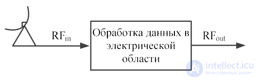
Figure 1.1 – Traditional method of processing RF signals
The first MWP systems were used to transmit electrical
signals in the optical domain, as shown in Figure 1.2. An electro-optical
conversion device (E/O), typically a Mach-Zehnder modulator or
an electro-absorption modulator, transferred the useful electrical signal onto
one or more optical carriers, which were transmitted over the optical medium
(the optical fiber) and then recovered in the electrical domain by
detection with opto-electronic converters (O/E), PIN photodetectors [15]. Such systems are known as microwave photonic links.
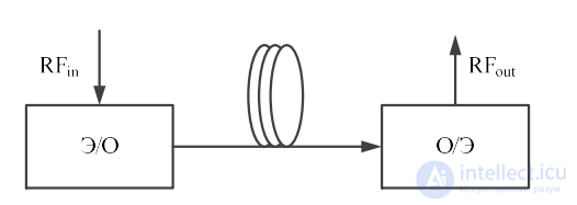
Figure 1.2 – Optical link for transmitting RF signals
Their main advantages are owed to the properties of the propagation medium,
such as a constant low attenuation coefficient across the entire
frequency range of modulating signals in the centimeter and millimeter
domains, which allows signal transmission over long distances with
low signal degradation; independence from the data format, which means that
low-frequency and high-frequency signals can be transmitted with the same
performance; large bandwidth; adaptability to various
network-implementation scenarios owing to the flexibility of optical fiber
cables; low weight and volume; immunity to electromagnetic interference. These
features have made it possible to implement Radio-over-Fiber (RoF) data-transmission
networks, which provide the transmission of a radio signal, typically
of the centimeter or millimeter range, from a central station (CS)
to one or more (BS) [18]. The concept of hybrid data-transmission networks
should also include the combination of RoF networks and wireless data-transmission
networks [19]. This approach makes it possible to simplify the system by using a
centralized structure that includes an antenna module
located closer to the end user [20]. The optical carrier is
modulated by the useful RF signal either at an intermediate frequency or
directly at the radiation frequency. For clarity, this process is
demonstrated in Figure 1.3.
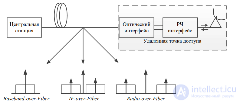
Figure 1.3 – Examples of forming a modulated signal in hybrid data-transmission networks
The best option will depend on the number of BSs, although the latter
method (RoF) is the most common, because it allows the use of
simple BSs.
Fiber optics, in addition to transmitting microwave signals, can also be
used to process microwave signals directly in the optical
domain. Optical processing of microwave signals was first proposed in 1976
. Optical signal processing (Figure 1.4) offers unique capabilities for
handling ultra-wideband microwave signals across virtually the entire
spectral region of the centimeter and millimeter ranges, completely
eliminating the «bottleneck» limitations of fully electrical devices.
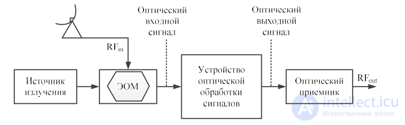
Figure 1.4 – Optical system for processing microwave signals
Moreover, optical signal processing using optical
waveguides offers new solutions related to building channels with
high throughput [21]. Thus, optical signal
processing represents a new approach to the question of signal processing,
which complements digital processing and analog processing using
microwave components [11]. Moreover, processing microwave signals
directly in the optical range makes it possible to avoid
costly opto-electronic conversions if the signals are already in the optical
propagation medium.
Areas of application of optical signal processing include microwave
filtering [26], Mb/s analog-to-digital converters [27-29],
mixers and frequency converters [30], signal correlators [31],
arbitrary-waveform signal generators [32], analog-to-digital
converters in the optical domain [33], [34] and radio-beam formers for
phased arrays (PAA) [35], schematically depicted in Figure 1.5.
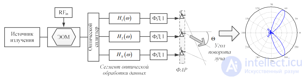
Figure 1.5 – Block diagram of PAA radiation-pattern formation
Unlike electrical filters, the response of photonic microwave filters does not
depend on the frequency of the electrical signal, because the center frequency
of the filter depends solely on the optical delay introduced into the structure.
In reality, in practical systems the frequency characteristic is
limited by the bandwidth of the electro-optical and opto-electronic
converters (modulators and photodetectors, respectively).
The process of processing radio signals directly in the optical domain
can be called discrete optical processing of microwave signals. It consists of sampling the input modulated optical signal,
processing the samples, and further structuring them with the aid of optical
delay lines and other photonic devices [36]. The processed
optical signal is then detected by opto-electronic devices. In addition to the
advantages listed, methods of discrete optical processing of microwave
signals can provide very short time delays, which leads to
ultra-high sampling rates (over 100 GHz compared with a few
gigahertz in the domain of digital signal processing). Moreover, operating
in the optical domain makes possible both spatial and frequency
division of channels thanks to WDM technologies. Figure 1.6 demonstrates the application of WDM technology.
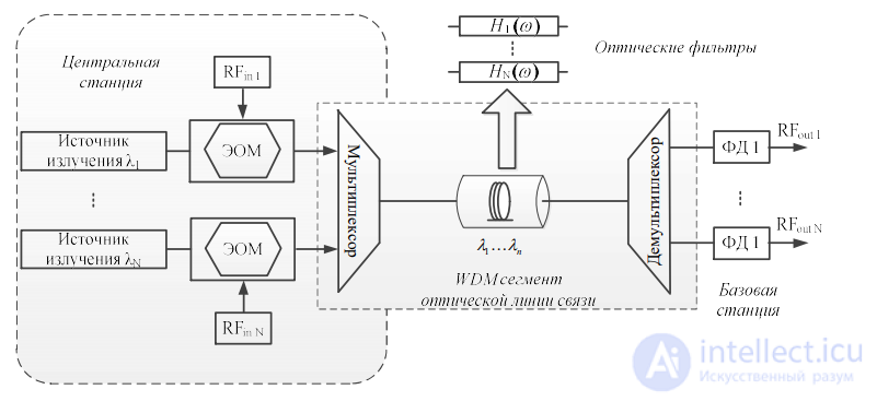
Figure 1.6 – Multiport WDM optical data-transmission networks
In general, the technology under consideration is attractive for
hybrid data-transmission systems [37], since the antenna receives not only
the useful signal but also various interference, which subsequently leads to
interference in the optical transmission lines. The ability to filter out
unwanted signals directly in the optical domain is a
unique characteristic of photonic filters. Also, a photonic filter
can be used as a bandpass filter to pass the required
band of frequencies [38]. Moreover, the required spectral band can
be changed given the ability to reconfigure and tune the filter. In both
cases, the passband window can vary from a few MHz to tens of GHz.
Traditionally, the formation of a microwave signal takes place in electrical
circuits and has a multi-stage character of frequency conversion. These
systems are complex and economically unfavorable. In addition, in many applications
the generated microwave signal must be transmitted over a remote distance, and
carrying out this action in the electrical domain is impractical
owing to the large attenuation when transmitting over a coaxial cable.
The solution to the task is the transmission of the microwave signal over an optical fiber [39].
Consequently, the question of generating a microwave signal in the
optical domain becomes relevant.
The traditional approach to the formation of a microwave signal is considered to be
generating it based on the superposition of two optical waves with different
frequencies arriving at a photodetector. An electrical
signal is then formed with a frequency corresponding to the wavelength spacing of the optical sources
[40]. This approach makes it possible to obtain a signal in the electrical range with a
frequency exceeding the THz range, but it has a substantial drawback: owing to
the incoherence of the optical sources, the generated microwave signal will
have significant phase noise. Recently, a
large number of methods for generating a microwave signal have been proposed. They can be classified into
4 categories:
1) sideband optical injection locking
2) optical phase-locked loop,
3) microwave generation using external modulation, and
4) dual-wavelength radiation source.
The first method consists in maintaining high coherence of the
radiation sources. The scheme for implementing the method is depicted in Figure 1.7a.
Owing to frequency modulation on the master laser, a
carrier and sidebands of various orders are formed at its output. The
signal of the master laser then arrives at two other lasers, whose carriers
are close to two symmetric sidebands. Thus, the carrier
of one of the lasers is locked to the 2nd-order sideband of the master laser, while the carrier of the other laser is locked to the
2nd-order sideband of the master laser. Taking into account the phase correlation
of the slave lasers, the generated microwave signal has a low level of
phase noise. In addition, with a certain configuration, the frequency of the
generated microwave signal after detection is an integer
multiple of the frequency of the modulating RF signal.
The second method of achieving phase coherence of two optical
sources consists in creating a phase-locked loop, as shown
in Figure 1.7b. After detection of the optical signal of the two radiation
sources, its phase is compared with the phase of a reference signal. A phase
detector generates a current proportional to the phase difference, which
arrives at one of the lasers along a feedback line to correct the phase
of the radiation by changing the laser cavity length or the injection current.
With proper tuning of the feedback-loop gain and the response time,
the relative phase between the two lasers will be significantly reduced, and,
consequently, the phase of the generated signal will correspond to the phase
of the reference signal of the microwave oscillator. A requirement for a high figure of
merit of this system is the condition of a narrow spectral linewidth
of the lasers, in order to ensure low-frequency phase fluctuations. Also
known is the approach of jointly using the first and second methods of
forming a microwave signal [46].
To implement the third approach, external modulators are used.
The best known of them is the Mach-Zehnder modulator. But its
use also has a drawback, caused by drift of the operating point on the
transfer characteristic of the modulator. The solution to the problem is the
use of an optical phase modulator [57]. The latter differs in that
it forms in the optical domain both the carrier and both sidebands,
so a narrowband notch filter is used to
eliminate the optical carrier. A drawback of this method is that
the sidebands transmitted over SMF fiber will experience the influence of chromatic dispersion, which in turn will change the phase
relationship between them. To avoid the negative consequences, it is necessary to
use methods of chromatic-dispersion compensation.
The last method of generating a microwave signal uses a radiation source
capable of generating two carriers with the required frequency spacing.
Because the radiation will be generated from a single source,
the coherence of the carriers will be at a high level. An advantage of implementing
this method is the absence of a microwave reference oscillator, which significantly
cheapens the structure. The key elements in the scheme in Figure 1.7c are
FBG-1 with two ultra-narrow passbands, fabricated using the technology
of relative phase shift, and FBG-2, made on the principle of superposition
of two standard FBGs.
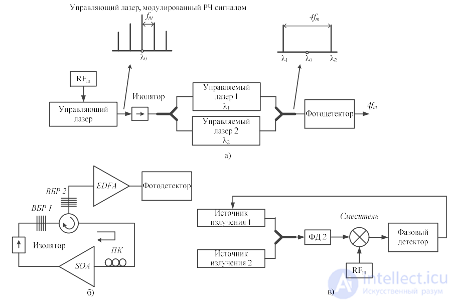
Figure 1.7 – Block diagrams of systems for forming a microwave signal in the optical domain
Two main approaches are distinguished in the methods of forming and controlling radio beams in radiating systems (RS):
- optical true-time-delay (TTD) systems, which introduce a frequency-invariant time delay by means of the optical propagation
medium and are characterized by a wide bandwidth
- coherent phase-shift optical beamformers, based on optical heterodyning and precise tuning of the phase of the optical
carrier to form the phase difference of the microwave signal
The various methods of forming and controlling the radio beam are considered in more detail below.
In the structures of spatial optical radio-beam formers,
spatial light modulators (SLM) are, as a rule, used to
control a set of optical channels, which can be controlled
independently. The optical channels are distributed among
photodetectors, which makes it possible to control the radiation pattern (RP) with the
aid of TTD. Figure 1.8 depicts the block diagram of Dolfi [60],
which is an example of a former of a two-dimensional TTD signal in free
space based on delays with polarization switching using
an SLM. The radiated signal is distributed across channels, and for
each channel the beam passes through N pixels of the SLM. Each pixel acts
as a voltage-controlled polarization rotator, which, in combination with
a polarizing beam splitter (PBS), switches the beam between one of two
propagation paths. N units provide time delays in
geometric progression (1T, 2T, ..., 2(N-1) T), where T is the time increment.
The time delay between the outputs determines the steering angle of the RP in the far zone.
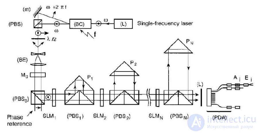
Figure 1.8 – Block diagram of an optical former with an SLM
Photonic implementations of the Rotman lens (Figure 1.9) have also been proposed
[61-62]. In [62] the photonic block consists of a slab waveguide, similar in
design to its radio-frequency counterpart with photodetectors as
interfaces connected to transmitting antennas, and whose shape can
realize a linear phase variation with different slopes.
Photonic implementations of the Blass matrix [63-64] also exist.
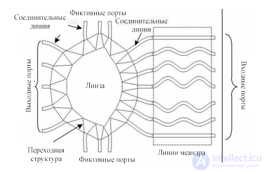
Figure 1.9 – Rotman lens
Yet another example of the implementation of spatial radio-beam
forming is the work [65], where the TTD is formed by means of a microelectromechanical system of micromirrors, in which light is reflected between
spherical mirrors a fixed number of times.
Programmable time-delay devices can be created using single-mode optical fiber, at the core of which
will lie the propagation delay of optical radiation. Figure 1.10 shows the block diagram of a programmable fiber-optic delay
line (FODL) based on single-mode fiber and optical switches.
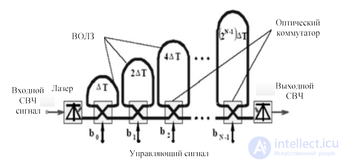
Figure 1.10 – Block diagram of a programmable fiber-optic delay line
The optical signal passes through cascaded optical switches and N fiber-optic delay lines, whose length increases in geometric progression. This concept requires one FODL per each radiating element of the system, which reduces the potential for practical use in large radiating systems.
Schemes of passive optical radio-beam formers based on a fiber-optic implementation of the Rotman lens [68-
70] have also been considered. Such systems contain FODLs of the appropriate length to form the required RP of the radiating system. The schemes may also contain optical amplifiers and
splitters.
In 1992, R. Soref proposed a new concept of FODL based on the dispersion properties of optical fiber. The main idea was to simplify existing schemes and components by parallelizing the time delay (the parallelism concept) [71]. To implement this idea, an equal number of lasers and radiating elements in the system was required. For further
simplification of the photonic equipment used in radio-beam forming systems and the forming of several radio beams simultaneously, WDM technology
came into wide use.
The concept of an optical radio-beam former based on a dispersive prism was proposed by R. Esman and his colleagues. The fiber prism was implemented by combining optical fibers of the appropriate length with high and low dispersion coefficients. The block diagram of the former is depicted in Figure 1.11.
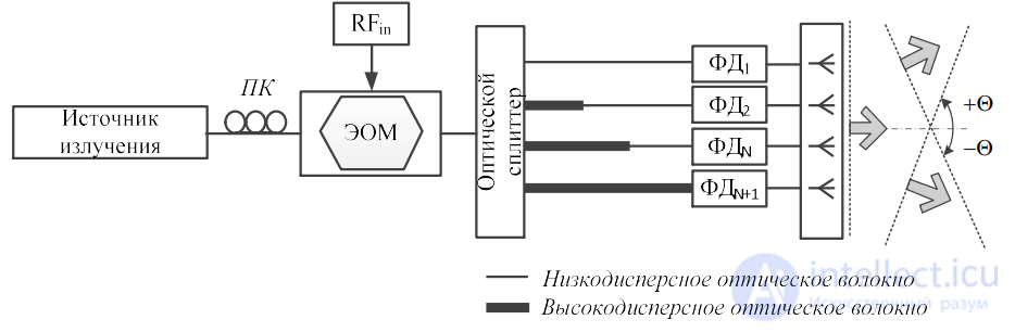
Figure 1.11 – Block diagram of an optical radio-beam former based on a dispersive prism
For the central optical wavelength, the dispersion magnitude is zero, which
forms the initial position of the RP of the radiating system. As the
optical wavelength increases (decreases), the high-dispersion optical fiber adds
(subtracts) a time delay, which leads to a change in the phase between
the elements of the radiating system. Subsequent improvement of the technology in the area of optical technologies made it possible to reduce the weight-and-size figures [78,
79].
Bragg optical gratings were also applied to implement TTD by obtaining a time delay through their dispersive properties. The signal
of a tunable optical laser was reflected from a broadband Bragg grating and formed the required time delay between the radiating elements of the system [80].
Chirped Bragg gratings also found application, which made it possible to increase
the reconfigurability of the system [81, 82]. But these systems are subject to
amplitude and phase distortions.
Integrated optical lines can be implemented on various
types of substrates. Planar lightwave circuits (PLC) [83] based on silica
waveguides were used in the works [84, 85].
Integrated optical technologies found an alternative implementation
in microring resonators based on the technology of integrating
CMOS and planar optical waveguides [86].
A drawback of such systems is the forced trade-off between
the maximum possible time delay, the operating frequency, and the
bandwidth, since the linear response of the optical delay line strictly
depends on the frequency of the radio signal. Eliminating this drawback was considered
in the work [87], where a new approach based on the use of ring
resonators proposed separate tuning of the optical carriers.
Another structure was proposed in the work [88], where the optical delay
lines were implemented on the basis of combining an integrated
sequence of resonators. Such a design reduces the negative
effects of group-delay dispersion and provides a wide
bandwidth and continuous tuning of long delays without distortions.
Another category of optical formers is coherent phase-shift optical beamformers, based, as a rule, on
heterodyne optical sources whose beat frequency corresponds to the frequency of the microwave signal. Control of the phase of the microwave signal is carried out by means of
controlling the relative phase of the optical signal [89, 90].
This type of former is based on the three-dimensional spatial Fourier transform of the function of optical lenses and the relationship between the front
and back focal planes. In the work [91] the spatial distribution of the light amplitude in the front focal plane is transformed by the optical Fourier transform into a phase distribution in the back focal plane of the lens. Sampling of the signals in the back focal
plane is performed with the aid of a set of microlenses or bundles of optical fibers connected to the radiating elements of the system.
The main advantage of this approach is compactness and simplicity. Nevertheless, the fabrication of a spatial fiber-optic
matrix with a specified precision is quite problematic within the framework of mass production.
In the works [92, 93] it was proposed to use an SLM to create a relative phase shift together with TTD methods to form
time delays with the goal of reducing insertion losses and increasing the reconfigurability of the system. Works are also presented that use
WDM technologies in coherent structures based on an SLM [94], where spatial and spectral channel division
was used to build a multi-beam heterodyne radio-beam former. In the work [84] a heterodyne optical waveguide system
for forming and controlling the RP of a radiating system, integrated on an electro-optical lithium niobate substrate, is described. Other works give examples of synthesizing optical radio-beam formers integrated on indium phosphide substrates [95, 96] and PLC based on silica substrates [97].
Table 1 gives the advantages and disadvantages of the considered radio-beam former systems based on photonic technologies.
Table 1 - Classification of photonic radiation formers
| Class | Technology | Advantages | Disadvantages |
|
Optical |
Based on spatial light modulators |
-High performance of parallel processing -Multi-beam propagation capabilities |
Significant insertion losses -Stability against environmental conditions -Significant size -Need for fast spatial optical modulators |
|
Optical |
Based on a photonic Rotman lens |
-Multi-beam propagation capabilities -Wide frequency band of the former -Compactness of the design |
-Significant insertion losses -Limited scalability -Limited resolving capability -Fast switches are required for RP-angle steering |
|
Optical |
Based on switched fiber-optic delay lines |
-High flexibility -Beam-steering |
-Limited scalability -Large dimensions - Fast switches are required for RP-angle steering |
| Optical formers with true-time-delay technology |
Based on a fiber-optic Rotman lens |
-Multi-beam propagation capabilities -Easy implementation -Independence from radiation wavelength |
-Limited scalability -Large dimensions - Fast switches are required for RP-angle steering |
| Optical formers with true-time-delay technology |
Based on microring optical resonators |
-Integrated device |
-Trade-off between bandwidth and delay -High delay ripple -Significant insertion losses -Dependence on radiation wavelength -Complexity of implementation |
| Optical formers with true-time-delay technology |
Esman optical prism, based on high/low dispersion optical fiber |
-Wide frequency band of the beam former -High flexibility -Multi-beam propagation capability at low complexity of the beam-former device -Limited number of optical connections -Beam steering by means of the radiation source |
-Need for a large length of fiber-optic link -Significant dimensions -Temperature sensitivity |
| Optical formers with true-time-delay technology |
Based on WDM using a Bragg grating |
-Wide frequency band of the beam former -High flexibility -Low insertion losses -Multi-beam forming capabilities at low complexity - Beam steering by means of the radiation source - Limited number of optical connections |
-Large number of Bragg gratings -High cost of the system -Multipath interference for Bragg gratings |
| Coherent optical phase-shift beamformers |
Beamformers of the Fourier transform |
-High parallelism -Low weight-and-size figures |
-High insertion losses -Opto-mechanical alignment of structures -Stability against environmental conditions -Need for a matrix of fast spatial optical modulators |
| Coherent optical phase-shift beamformers |
Hybrid beamformer based on arrays of spatial optical modulators |
-High parallelism -Low weight-and-size figures |
-High insertion losses -Stability against environmental conditions -Need for fast spatial optical modulators |
| Coherent optical phase-shift beamformers |
Beamformer based on an integrated lithium niobate or silicon semiconductor phase shifter |
-Low weight-and-size figures |
-High insertion losses -Limited scalability -Dependence on environmental conditions -Significant power consumption |

Comments