
Lecture
A feed − is a lumped element of a parabolic antenna, located at its focus (phase center) or focal plane, which forms the antenna's radiation pattern and polarization.
The feed is not a standalone antenna. It solves only one task: to evenly «spread» the energy arriving via the feeder from the transmitter across the surface of the reflector so as to obtain the maximum gain of the entire system
A feed horn (or feedhorn) is a small horn antenna used to convey the waveguide feed, for example, to parabolic antennas or offset parabolic antennas for receiving or transmitting microwave signals. A typical application is its use for receiving satellite television with a satellite dish. In this case, the feed horn may be either a separate part used, for example, together with a «low-noise block downconverter» (LNB), or, more typically today, integrated into a «low-noise block feedhorn» (LNBF).

The main characteristics of feeds include:
Feeds, depending on their cost, tasks and operating band, are circular or rectangular conical horns that form a radiation pattern identical in the E and H planes. To equalize the patterns and reduce the side lobes, the horns may be made with internal grooves.
The aperture of the feed often has dimensions comparable to its operating wavelength, unlike other elements of the antenna-feeder path, above all the antenna reflector, whose dimensions are usually orders of magnitude larger than those of the polarizer, filters, etc.
A passive feed is often a coaxial-to-waveguide transition or a conical horn, although many other designs exist as well. The receive output of the feed is structurally connected to the LNA, the transmit output to the frequency converter path or to the transmitter. Such close placement of the LNA to the feed is explained by the need to minimize losses in the path at high frequencies. After the LNA with the frequency converter, the signal is transmitted to the receiver at lower frequencies.
Several different feeds can operate in a single antenna, located at its focus or focal plane. Accordingly, they can form the antenna's RP in different directions of signal reception-transmission, of different polarization and different frequency band. This variant is used when working simultaneously with different space communication satellites.
The radiation pattern of the feed must be adapted to the dimensions of the reflector, because it has a strong effect on the aperture efficiency of the entire antenna, which determines its gain. Radiation from the feed that falls beyond the edge of the dish is called "spillover" wasted, reducing the antenna gain and increasing the side lobes, which in turn can cause interference in receiving antennas and increases susceptibility to extraneous high-frequency noise. The maximum effect is achieved provided that the reflector is uniformly illuminated with a constant field power at its edges amounting to 10 dB below the maximum of the feed's RP.
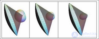
Effect of the width of the feed's RP on the antenna's RP. Left: the feed has a wide pattern and most of the power is scattered outside the reflector. Right: The feed has a narrow pattern and the reflector is not fully used.
As already mentioned, the feed is not a standalone antenna. It solves only one task: to evenly «spread» the energy arriving via the feeder from the transmitter across the surface of the reflector so as to obtain the maximum gain of the entire system. And for this:
The shape of the feed's RP must be matched to the shape of the reflector and its f/D (sections 13.7.2, 13.7.2.3). That is, it must have an RP width specified in accordance with f/D (section 13.7.2.2). And this width must be identical (or close) in the horizontal and vertical planes (since reflectors are mostly circular).
The side and back lobes of the feed must be minimal, since they cause a loss of gain and an increase of the side lobes of the parabolic antenna.
The phase center of the feed must be point-like, not smeared out in space. In addition, its position in both planes must coincide or be close.
The feed must have the ability to tune the SWR. The wave reflected from the reflector, falling back into the feed, changes the field around it and, consequently, its input impedance. This is called the reflector's influence. Almost the same thing happens as in any antenna over a perfect ground (section 3.3.4). Only in our case the role of the ground is played by the reflector.
The area of the feed must be small (to reduce its shadowing of the reflector).
If the parabolic antenna is used for space communication (EME, for example), then the feed must have the ability to switch polarization.
Such a set of requirements makes creating a feed a difficult and not always achievable task.
The most difficult matter is realizing the specified shape of the three-dimensional RP. We need a directional antenna that uniformly «illuminates» the circular reflector and radiates nowhere else. That is, the feed is required to have a main lobe of conical shape with the same RP shape in the azimuthal and zenithal planes. This requirement follows from the geometry of the circular reflector (we do not seriously consider the case of elliptical reflectors, since it is practically unrealistic to make a reflector for a specific feed).
However, in almost all directional antennas both the shape and the width of the RP differ in the azimuthal and zenithal planes. For example, in a two-element Yagi-Uda at the –10 dB level in the azimuthal plane the RP has a width of 1200, and in the zenithal plane – 2100.
The reason for such a difference in the dissimilarity of the RP in the two planes lies with the single element of an end-fire antenna (and almost all feeds below 3 GHz are such). In the example with the Yagi-Uda antenna, a single dipole has a figure-eight RP in the azimuthal plane and a circular one in the zenithal plane. The use of a second element reduces this difference (due to the overall narrowing of the RP), but does not eliminate it.
Conclusions:
A single feed element must have RPs of similar shape in the zenithal and azimuthal planes. And for this it must have extent both horizontally and vertically (this, by the way, is why a Yagi-Uda antenna cannot be a good feed).
As the number of feed elements increases, the overall radiation pattern depends less on the RP of a single element. But the influence still remains. Thus, for a 12-element Yagi-Uda the width of the azimuthal RP is 540, and the zenithal 580.
The obvious solution: use loop elements. For example, in a rectangular loop the azimuthal and zenithal radiation patterns are closest at a loop side ratio of 2:1 and feeding at the middle of the short side.
A two-element feed made of such loops is shown in Fig. 13.7.13, which gives the azimuthal and zenithal RPs simultaneously. Such a feed is suitable for a reflector with f/D = 0.45 (see Figs. 13.7.4 and 13.7.6).
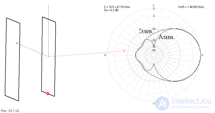
Fig. 13.7.13.
The feed of 3 loops, shown in Fig. 13.7.14, has a better match of the patterns. But they are narrower, so such a feed works on a reflector with f/D = 0.52 (see Figs. 13.7.4 and 13.7.6).
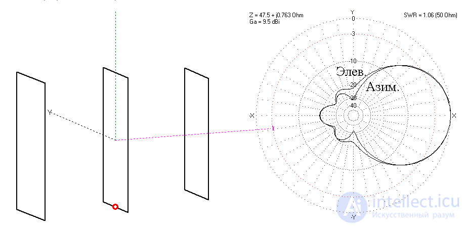
Fig. 13.7.14.
Despite the rectangularity of the loops, both feeds of the two previous figures have a correct conical RP, i.e. the RP shape is identical not only in the azimuthal and zenithal planes, but also for any plane rotated by an arbitrary angle relative to the X axis.
I have dwelt on this separately, because the identity of only the zenithal and azimuthal RPs does not yet guarantee the conicity of the beam (and, consequently, the uniformity of «illumination» of the reflector). For example, two in-phase dipoles with a small reflector (meaning a small feed reflector, not the main parabolic one) give a very good match of the shapes of the azimuthal and zenithal RPs (files ...2el_dip_obl.gaa, ...2el_dip_obl_m.gaa). But if one looks at the three-dimensional RP, it turns out that the shape of the main lobe is not conical but pyramidal, quadrangular, and that at angles of +450 relative to the X axis the RP shape is noticeably different from that in azimuth and in zenith. Consequently, such a feed will be suitable only for a square reflector.
A good option is the use of a zigzag element (Fig. 4.3.18a). True, when using the same element as a reflector (small), the RP comes out not very symmetric (approximately as in Fig. 13.7.14). But if you take a solid reflector, then, by selecting its dimensions, you can achieve almost complete matching of the shapes of the main lobe in azimuth and zenith. The optimal dimensions of the solid reflector come out to 0.76λ x 0.73λ (height by width). Such a feed is shown in Fig. 13.7.15. It is suitable for a reflector with f/D = 0.5 (see Figs. 13.7.4 and 13.7.6).
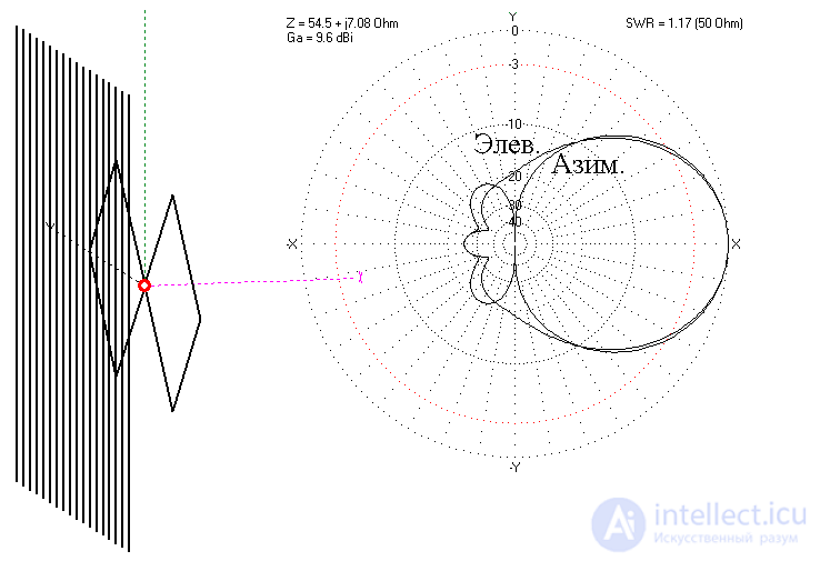
Fig. 13.7.15.
Let us note that by changing the dimensions of the feed's solid reflector one can achieve an improvement in the identity of the azimuthal and zenithal RPs.
This idea is brought to perfection in the RA3AQ feed, shown in Fig. 13.7.16. A loop radiator is placed into a cylindrical reflector 0.76λ in diameter and 0.21λ high, to a depth of 0.063λ. The match of the azimuthal and zenithal RPs is almost complete for all angles. Such a feed is suitable for a reflector with f/D = 0.42 (see Figs. 13.7.4 and 13.7.6).
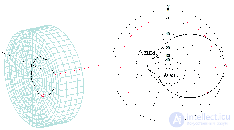
Fig. 13.7.16.
A variant of the previous feed with a reflector 0.731λ in diameter in the form of a spherical segment (its radius 0.77λ) is shown in Fig. 13.7.17. This feed differs from the previous one by a wider lobe, so it can «illuminate» a reflector with f/D = 0.4 (see Figs. 13.7.4 and 13.7.6).
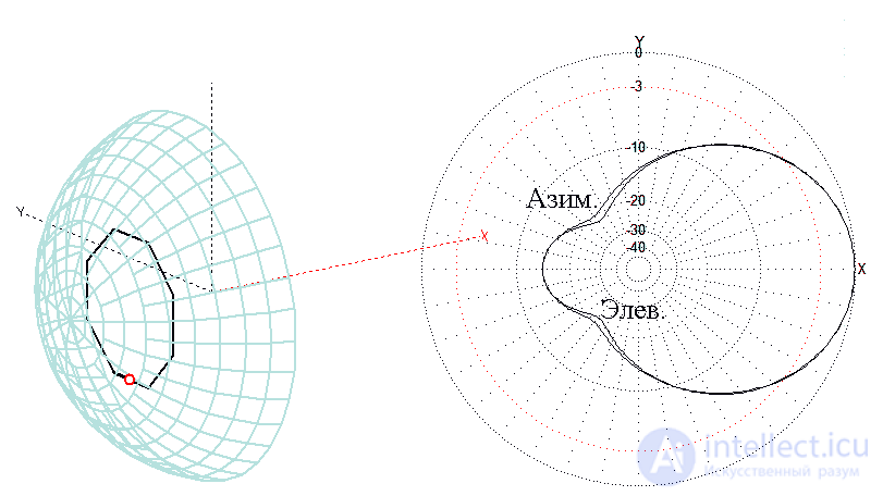
Fig. 13.7.17.
…Digressing from the current topic. A parabolic antenna with the feed of Fig. 13.7.17 can, with some (very slight) stretch, be considered a dual-reflector antenna. We will not consider dual-reflector systems (these are entirely professional antennas). But they exist and solve the same task: to uniformly «illuminate» and use reflectors with a small f/D. But let us return to our feeds…
In them more complex metal reflectors are also used. They are arranged in principle the same way as the feeds of Figs. 13.7.16 and 13.7.17: a metal cavity of complex shape, inside which an exciter antenna is located. This turns out to be a horn or an open end of a waveguide. This is usually done at frequencies above 3 GHz, so in this book we will not consider such feeds.
To change the direction of linear polarization the feed is rotated mechanically. If all polarizations are needed (including both rotating ones) and fast switching between them, then the RA3AQ feed or the one in Fig. 13.7.17 with two feed points (as in Figs. 12.2.18 and 13.4.12) and the switching scheme of Fig. 13.4.10 is used.
We have already spoken in general terms about the influence of the wave reflected from the reflector on the input impedance of the feed at the beginning of this section. Now let us look at this in figures. Fig. 13.7.18 gives graphs of the SWR of an initially tuned feed (having SWR = 1 without a reflector) as a function of the reflector diameter in λ for different f/D. These graphs are computed for a circular parabolic reflector with an edge excitation level of –10 dB.
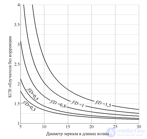
Fig. 13.7.18.
Fig. 13.7.18. From Fig. 13.7.19 it follows that the influence of the reflector on the feed's SWR is significant in most practical variants. It can be neglected only if a very large (several tens of λ in diameter) reflector with f/D < 0.5 is used. In all other cases the drift of the feed's SWR will be large and measures must be taken to match it (for example, changing the dimensions).
Let us figure out why the graphs of Fig. 13.7.18 look exactly this way. It is obvious that the influence of the reflector on the feed is the stronger the larger the part of the energy reflected by the reflector that passes through the feed.
It is clear why the SWR in Fig. 13.7.18 improves with increasing reflector diameter: the larger the diameter, the smaller the part of the aperture occupied by the feed. Consequently, most of the energy reflected from the reflector will pass by the feed without affecting it.
It is less obvious why an increase in f/D so greatly increases the influence of the reflector (i.e. the feed's SWR) that without matching adjustment of the feed the antenna system turns out to be practically inoperable. But this too becomes clear if one turns to the graphs of Fig. 13.7.4: the viewing angle of the reflector from the focus drops rapidly with increasing f/D to a few tens of degrees. In other words, for a long-focus (large f/D) parabola the feed must have a narrow RP, and, consequently, high gain and a large aperture area. And through this large area a significant part of the energy reflected from the reflector passes. In other words, the field in the near zone of the feed changes strongly. And this changes the input impedance and SWR.
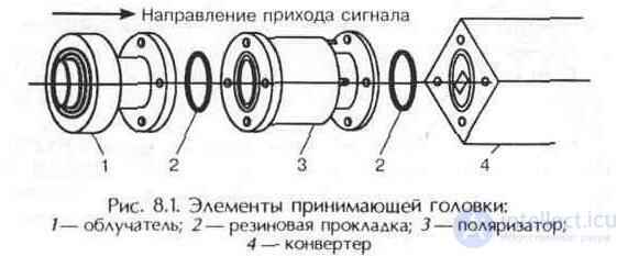
The receiving head, located at the focus of the antenna's parabolic reflector, consists of three parts: the feed, the polarizer and the converter (Fig. 8.1).
These functionally distinct blocks can be structurally combined and made in a single housing (in pairs or all three elements together).
The signal reflected by the parabolic antenna goes to the feed. Its purpose is to transmit the energy of the satellite's television transponder received by the antenna via the waveguide to the converter.
The feed is one of the most important units of the antenna system, so certain requirements are imposed on it: the radiation pattern must be axially symmetric and without side lobes; the feed must not strongly shadow the parabolic antenna, since this leads to distortion of its radiation pattern and a reduction of the surface utilization factor of the paraboloid of revolution.
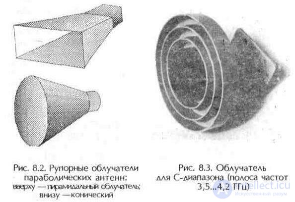
The feeds of parabolic antennas are weakly directional antennas. These can be horns, slot antennas, helices, dielectric antennas, etc. The simplest are feeds in the form of an open end of a waveguide — of rectangular or circular cross-section (Fig. 8.2).
A waveguide of circular cross-section satisfies to a greater degree the requirements imposed on the feeds of antenna systems — the radiation pattern is axially symmetric, unlike the pyramidal (rectangular) waveguide.
The designs of feeds for axially symmetric and offset antennas differ somewhat. This is due to the fact that a parabolic antenna is characterized by the ratio of its focal length to the diameter of the paraboloid of revolution (F/D).
Most axially symmetric satellite antennas now manufactured have an F/D parameter of about 0.3...0.4, and offset ones — about 0.5...0.6. Accordingly, feeds for axially symmetric and offset antennas are made with different «flare angles».
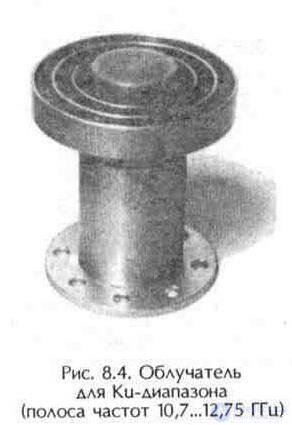
The design of modern feeds provides for three metal rings for better focusing of electromagnetic waves and providing a narrower antenna radiation pattern. Thus, the feed is a directional antenna that is mounted at the focus of the parabolic reflector (Figs. 8.3, 8.4).
The feed is installed for more complete use of the reflector surface and for realizing the maximum antenna gain.
An electromagnetic wave propagating in space from the transmitting antenna of the satellite to the antenna of the ground station is characterized by polarization, i.e. the orientation of the electric field intensity vector E relative to the Earth's surface (see Ch. 1, section 5).
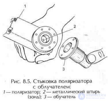
The polarizer is a device that provides the selection of the required type of polarization of the received radio wave. Usually the polarizer is installed between the feed and the converter (Fig. 8.5). During assembly it is important to ensure the tightness of the connection. Thus, for example, rubber gaskets must be precisely located in the metal grooves and have no misalignment.
By the principle of their operation, polarizers can be mechanical, ferrite (electromagnetic) and pulsed ferrite.
A mechanical polarizer includes a loop-like or pin conductor (3) (the coupling element with the converter's electrical path) and an actuating mechanism (6) (Fig. 8.6). The coupling element (4) enters the electromagnetic field of the waveguide and converts its ener-
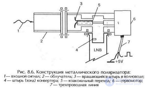
gy into an electric current. The same role is performed by any television antenna, which we are accustomed to seeing on the roofs of buildings or on masts.
In order for the maximum electromotive force to develop in the coupling element, which creates the greatest electric field in its conductor, it is necessary to give the probe the same position as the radiator of the antenna on the satellite. Accordingly, the receiving system must separate signals of one polarization from another and receive them separately.
In mechanical polarizers the transition from one polarization to another is carried out by raising the supply voltage from 13 V (V polarization) to 18 V (H polarization). A switching system allows obtaining two fixed values of polarization, the choice of which occurs by mechanical movement — rotation of the coupling element about its own axis with the help of a stepper motor. The presence of moving elements reduces the reliability of a mechanical polarizer.
In an electromagnetic polarizer (Fig. 8.7) the choice of polarization (Fig. 8.8) is carried out by changing the magnitude of the current in the coil (3) wound on a ferrite core (2). The reliability of such a polarizer is higher, since there are no moving mechanical parts. Moreover, current-controlled polarizers allow smooth adjustment of the polarization.
The polarization of the signal transmitted from the satellite is strictly parallel (H) or perpendicular (V) to the sur-
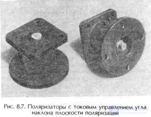
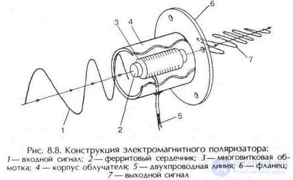
face of the Earth only at the longitude of the satellite itself. If reception is carried out further to the East or to the West, then due to the curvature of the Earth's surface the plane of polarization is more inclined relative to its surface. The farther the longitude of the reception point is from the longitude of the satellite, the greater this angle of inclination. Accordingly, the polarizer
is placed at a greater or smaller angle to the Earth's surface.
A similar problem arises in the case where the antenna is installed with positioning on several satellites. For each artificial satellite the angle of inclination is its own, so smooth current adjustment of the polarization is necessary. For each satellite its own value of control current and angle of inclination of the polarization plane to the horizon is chosen.
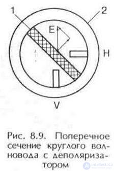
On European satellites (ASTRA, EUTELSAT, etc.) linear polarization is mainly used, and on Russian ones (GALS1, GALS2, TDF2) — only circular. To receive circular waves, another element is installed in front of the polarizer — a depolarizer, which converts circular polarization into linear (Fig. 8.9).
The device that converts one type of field polarization in a circular cross-section waveguide (2) into another is a section of waveguide in which there are longitudinal inhomogeneities in the form of dielectric plates (material teflon or other) (1) and metal rods (H or V). Obviously, the phase velocities of waves whose electric field intensity vectors E are parallel or perpendicular to the plates or rods are different.
Let a linearly polarized wave, whose vector E forms a 45° angle with the plane of the inhomogeneities, propagate in a circular cross-section waveguide with longitudinal inhomogeneities. Let us decompose this vector into two components: parallel and perpendicular to the plane of the inhomogeneity. At the input of the depolarizer both field components are identical and have identical phases. If the length, parameters and configurations of the plates or rods are chosen in such a way that at the output of the device the phase difference between the parallel and perpendicular components of the vector E equals 90° (3.14/2), then at the output of the device instead of a linearly polarized field we obtain a field with circular polarization. This is the 3.14/2 polarizer. If a field with circular polarization enters such a polarizer, then it is converted into a field with linear polarization. Depending on the position of the dielectric plate and the pins in the waveguide, circular polarization is converted into vertical or horizontal.
In a number of cases when receiving signals with both types of
polarization (linear from European satellites and circular from the Russian GALS and TDF2) one can do without a depolarizer. However, in this case a loss of 3 dB in the level of the circular signal will be incurred, which corresponds to an increase of the required antenna diameter by a factor of 1.4. For broadcasts from GALS this is not critical, since on the territory of the Republic of Belarus its signal is received, for example, in Minsk on a «dish» of significantly smaller diameter (0.6...0.9 m) than signals from any European satellite.
Polarizers also differ from the point of view of the discreteness (intermittency) of the change of polarization. In mechanical polarizers the plane of polarization changes discretely by 90°. Current-controlled polarizers allow smooth change of the plane of polarization.
There also exist pulsed-ferrite polarizers, in which the polarization probe is moved with the help of a mechanism. To control this mechanism a sequence of pulses is sent to the polarizer, the duration of which carries information about the required position of the polarizer. In such polarizers the plane of polarization changes discretely, but with a small discretization step.
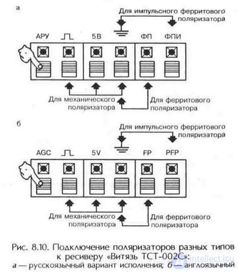
Electromechanical polarizers require three control signals from the receiver, while magnetic ones need only two (Fig. 8.10).
The advantage of electromechanical polarizers compared to magnetic ones is somewhat lower signal losses. Nowadays electromagnetic polarizers are used mainly in C/Ku rotors.
Example of a non-standard feed design
WBME — Wide Band Magneto-Electric dipole — was proposed by two Chinese scientists - Kwai-Man Luk of the City University of Hong Kong and Mingjian Li of the University of Wisconsin in Madison (USA) in 2012-2015. It can be represented as a superposition of two elementary radiators. The first radiator is a half-wave dipole, which is equivalent to an elementary electric dipole. The second radiator is a short-circuited quarter-wave patch, whose radiating slot is equivalent to an elementary magnetic dipole. Together the patch and the half-wave dipole constitute a magneto-electric dipole, which, in turn, is equivalent to the Huygens element well known in theory, with a radiation pattern in the shape of a cardioid.
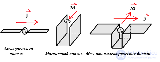
Let us draw the reader's attention to the fact that the concepts of «magnetic dipole», «electric dipole», «Huygens element» are virtual mathematical abstractions from antenna theory. The «half-wave dipole», «short-circuited quarter-wave patch», «magneto-electric dipole» are real antennas that can be touched with the hands. Note that in the English-language literature the abstract elementary electric dipole and the real dipole are denoted by one word — dipole. This can lead to confusion of concepts. In essence, abstractions are intended to simplify the understanding of the physics of phenomena, but for a practitioner accustomed to working with real hardware, abstractions are perceived rather with difficulty.
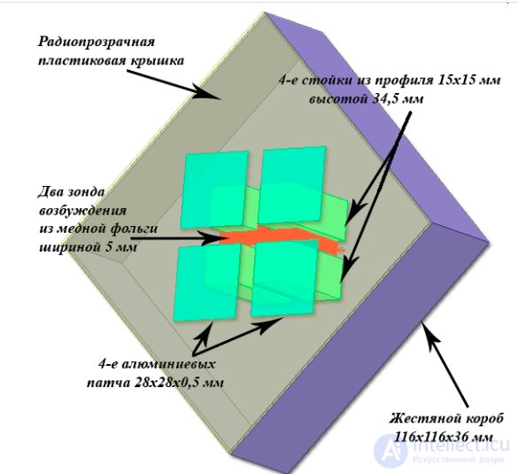
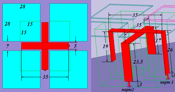
The criteria for choosing a feed are as follows:
The horn minimizes mismatch losses between the antenna and the waveguide. If a simple open-ended waveguide were used, without a horn, the sudden end of the conducting walls causes an abrupt change of impedance at the aperture between the wave impedance in the waveguide and the impedance of free space.
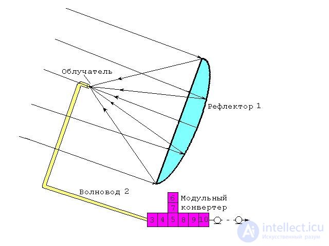
Fig. 14. Axially symmetric parabolic antenna.
When used with an offset, parabolic or lens antenna, the phase center of the horn is placed at the focal point of the reflector. The feed characteristic is usually chosen with the 3 dB points of the horn's radiation pattern falling on the edge of the reflector (the horn's beamwidth corresponding to the F/D ratio of the satellite dish). ] When the shape of the antenna deviates from a circular dish, the horn must have a corresponding shape in order to illuminate the antenna correctly.
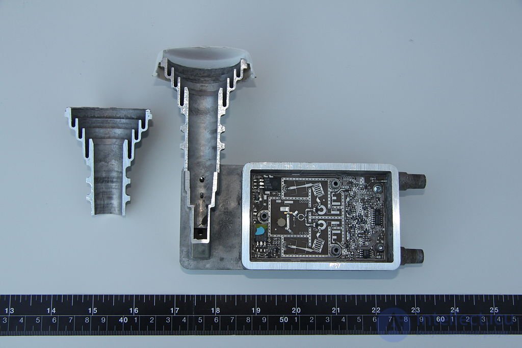
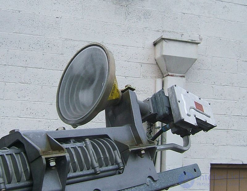
A feed for a satellite communication antenna is a conical horn with a circular pattern
For receiving satellite TV the horn is mounted on the arm of the satellite antenna. Then the horn is connected via a short waveguide to the «low-noise block downconverter» (LNB), a small housing containing part of the receiving electronics (also called the «RF front end»). This LNB converts the high downlink satellite microwave frequencies into lower frequencies, so that the television signals can be more easily transmitted through coaxial cables to receivers located anywhere inside the building. For DTH TV, the LNB and the feed horn are usually combined into a single unit called a «low-noise block feedhorn» (LNBF), but for more specialized applications separate horns and LNBs are used.
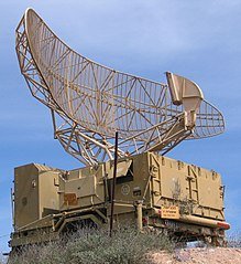
For the satellite uplink (for example, for transmitting DTH «Direct-To-Home» TV programs, satellite news gathering SNG, satellite Internet access or VSAT applications) a block upconverter (BUC) is connected via a waveguide to the horn for transmission via the satellite antenna to the communication satellite.
Feed horns are also used in applications such as radar, microwave line-of-sight transmission or radio astronomy.

Comments