
Lecture
The invention relates to the field of radio engineering and electronics and may be used to protect computer equipment against information leakage caused by spurious electromagnetic emissions. The object of the invention is to broaden the spectrum of the output signal while simultaneously improving the uniformity of the power spectral density and the stability of the noise-signal generation regime. The essence of the invention is that a noise-signal generator, containing first and second interconnected self-oscillators, first and second unbalanced strip lines (USLs) and a first capacitor installed in a housing-screen, additionally contains a third USL, second and third capacitors, and first, second and third resistors; each of the self-oscillators is implemented on two transistors in a push-pull common-emitter configuration; the first, second and third USLs are made in the form of a three-start Archimedean spiral; the bases of the first transistors of the first and second self-oscillators and the bases of the second transistors of the first and second self-oscillators are connected in pairs and coupled to the initial section of the first USL; the collectors of the transistors of the first and second self-oscillators are coupled to the initial sections of the second and third USLs respectively; the ends of the second and third USLs are joined and, through the second resistor, connected to the positive terminal of the power supply, which is connected through the third resistor to the end of the first USL; the first capacitor is connected between the second and third USLs; the second and third capacitors are connected between the first and third USLs. 2 figures.
The invention relates to the field of radio engineering and electronics and may be used to protect computer equipment (CE) and radio-electronic equipment (REE) against information leakage caused by spurious electromagnetic emissions, as well as in measurement technology.
Patent 2097906 Patent authors: Kadeev A.M. Fadeev N.M.
An effective method of preventing information leakage from CE and REE is the active radio-engineering masking of spurious electromagnetic emissions by means of noise-signal generators.
The most important requirements imposed on noise-signal generators of this kind are: a broadband output-signal spectrum, dictated by the broadband nature of spurious electromagnetic emissions; high uniformity of the noise power spectral density; stability of the noise-generation regime; high efficiency; small dimensions and mass.
The noise-signal generators known from the literature do not satisfy the combination of the listed requirements.
A noise-signal generator with delayed feedback is known [1, Fig. 9.101], containing a traveling-wave tube (TWT) as the nonlinear active element, a resonant filter and a delay line (DL). Such a generator has large dimensions and mass. Powering it requires a special power supply that is likewise distinguished by large dimensions and mass. These drawbacks impede the widespread use of generators of this type.
Semiconductor noise-signal generators are more promising and more attractive in terms of dimensions and mass, as well as in other respects.
A noise-signal generator is known that contains a nonlinear converter, a DL and a bandpass filter connected in a ring, the nonlinear converter being made in the form of a multistage amplifier with intra-stage and inter-stage feedback circuits through sections of the DL, which is made multi-tapped from LC sections.
The drawbacks of this generator include low efficiency, instability of the noise-signal generation regime when the supply voltage changes, and poor spectral uniformity.
Also known is a noise-signal generator containing a pump source in the form of a frequency-controlled self-oscillating unit, a first inductor, an oscillator consisting of a negative-resistance element and an LC oscillatory circuit formed by a second inductor and a nonlinear capacitor, as well as a coupling element. In this device, by providing control of the self-oscillating unit's frequency according to a random law, a certain improvement in spectral uniformity is achieved. However, the device is narrowband and cannot be effective when used to prevent information leakage from CE and REE.
The closest to the claimed device in technical essence and in the combination of essential features is the noise-signal generator per the invention selected as the prototype. This generator contains [4, Fig. 2] first and second interconnected self-oscillators with, respectively, first and second unbalanced ring-shaped microstrip lines, a feedback capacitor, and an output microstrip line with a decoupling capacitor. Each of the self-oscillators is implemented on a single bipolar transistor.
The drawbacks of the prototype include: a comparatively narrow output-signal spectrum, limited at the low end because of the insufficient broadband nature of the oscillatory system; relatively low uniformity of the noise-signal power spectral density; and low stability of the noise-signal generation regime when the supply voltage changes.
The object of the invention is to broaden the output-signal spectrum while simultaneously improving the uniformity of the power spectral density and the stability of the noise-signal generation regime when the supply voltage changes.
The object is achieved in that a noise-signal generator, containing 1st and 2nd interconnected self-oscillators with 1st and 2nd unbalanced strip lines (USLs) and a 1st capacitor installed in a housing-screen, additionally contains a 3rd USL, 2nd and 3rd capacitors, and 1st, 2nd and 3rd resistors; each of the self-oscillators is implemented on two transistors in a push-pull common-emitter configuration; the 1st, 2nd and 3rd USLs are made in the form of a three-start Archimedean spiral; the bases of the first transistors and the bases of the second transistors of the first and second self-oscillators are connected in pairs and coupled to the initial section of the 1st USL, which is connected to the 1st terminal of the 1st resistor, the 2nd terminal of which is connected to the housing; the collectors of the transistors of the 1st and 2nd self-oscillators are coupled to the initial sections of the 2nd and 3rd USLs respectively; the ends of the 2nd and 3rd USLs are joined and, through the 2nd resistor, connected to the positive terminal of the power supply, which is connected through the 3rd resistor to the end of the 1st USL; the 1st capacitor is connected between the 2nd and 3rd USLs; the 2nd and 3rd capacitors are connected between the 1st and 3rd USLs; and the output of the generator is any point of the 2nd and 3rd USLs.
The technical result of the invention consists in a manifold broadening of the output-signal spectrum while simultaneously improving the uniformity of the noise-signal power spectral density and the stability of the noise-signal generation regime when the supply voltage changes. In particular, the frequency coverage ratio in the proposed device is 100,000 times, compared with 8 for the prototype.
The achievement of the stated technical result can be explained by the increase, in the proposed generator, of the number of degrees of freedom compared with the prototype, owing to making the USLs in the form of a three-start Archimedean spiral whose turns are inductively coupled to one another, connecting the collectors of the two pairs of self-oscillator transistors to the bases through the USLs and feedback capacitors, and connecting the oscillatory system to the power supply through a current-limiting resistor. As a result, a complex dynamic oscillatory system is formed with ultra-deep positive feedback and a large number of oscillatory circuits with different resonant frequencies and with chaotic variation of these frequencies, as well as of the phases of the onset and cessation of the high-frequency oscillations. The output-signal spectrum of such a system is practically continuous over a wide frequency band, and the power spectral density has high uniformity.
The large number of degrees of freedom also determines a higher stability of the noise-signal generation regime when the supply voltage changes.
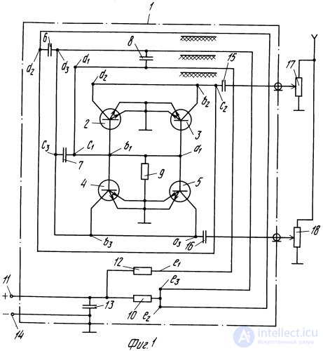
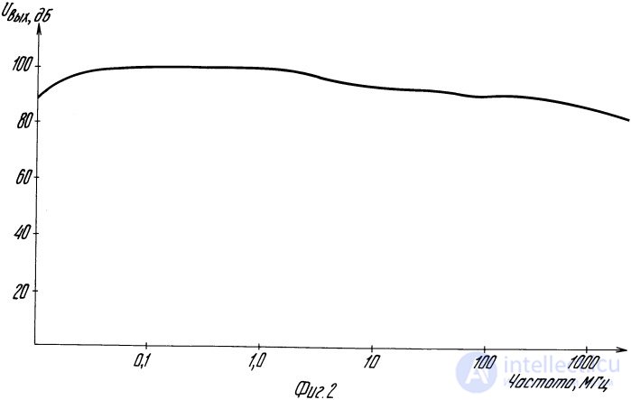
Fig. 1 shows the electrical schematic of the proposed device; Fig. 2 shows its amplitude-frequency response (AFR).
The claimed device contains (Fig. 1): a housing-screen 1; first and second interconnected push-pull self-oscillators, made in the common-emitter configuration on transistors 2, 3 and 4, 5 respectively, with a first USL a1b1c1d1e1, a second USL a2b2c2d2e2 and a third USL a3b3c3d3e3; a first feedback capacitor 6 connected between the second and third USLs; second 7 and third 8 feedback capacitors connected between the first and third USLs; a first resistor 9, one terminal of which is connected to the initial section a1b1 of the first USL and the other is connected to the housing; a second resistor 10, one terminal of which is connected to the positive terminal 11 of the power supply and the other terminal to the ends of the second and third USLs; a third resistor 12 connected between the end of the first USL and the positive terminal 11 of the power supply; a bypass capacitor 13 connected between the positive 11 and negative 14 terminals of the power supply; decoupling capacitors 15 and 16 for taking off the output signals through an output-level control on variable resistors 17 and 18.
The first, second and third USLs form a three-start Archimedean spiral; the bases of the first transistors 2, 4 and the bases of the second transistors 3, 5 of the first and second self-oscillators are connected in pairs and coupled to the initial section of the first USL at points b1 and a1 respectively; the collectors of transistors 2 and 3 of the first self-oscillator are coupled to the initial section a2b2 of the second USL; the collectors of transistors 4 and 5 of the second self-oscillator are coupled to the initial section a3b3 of the third USL; the ends e2 and e3 of the second and third USLs are joined to each other and connected to the terminal of resistor 10. The bypass capacitor 13 may be installed in the power supply. The decoupling capacitor 13 may be installed in the power supply. The decoupling capacitors 15, 16 and the noise-signal level control on resistors 17 and 18 are shown in Fig. 1 as an example of a possible implementation of the generator's output-signal pickup device. In principle, the output of the generator may be any point of the second and third USLs.
Each of the USLs is made in the form of a turn and therefore constitutes an inductance. Owing to their being located in immediate proximity to one another, all three USLs turn out to be inductively interconnected. Capacitors 6-8 determine the electrical coupling between the USLs; on the one hand these capacitors provide feedback, and on the other hand they are the capacitors of the oscillatory circuits. As a result, a complex oscillatory system is formed with a large number of oscillatory circuits and degrees of freedom, giving rise to ultra-deep hard positive feedback in the self-oscillator circuit. The oscillatory system also includes the distributed capacitance between the USLs and the housing. The oscillatory system is connected to the power supply through resistor 10, i.e. it is not purely reactive but lossy.
The operation of the proposed device is based on the principle of intermittent generation of high-frequency oscillations repeating at a low frequency. The root cause of the system's stochastic behavior is the natural fluctuations of the initial conditions for the onset of the high-frequency oscillations, whose amplitude, owing to the super-regenerative amplification effect, receives a significant increment but does not reach the stationary value determined by the nonlinearity of the active elements, since energy is delivered to both self-oscillators from a single power supply through common resistor 10, which limits the current of the active elements. With the saturation of the active elements and the charging of the oscillatory-circuit capacitors, there occurs a sharp decrease in the current through these elements, after which, owing to the deep positive feedback, the oscillatory-circuit capacitors discharge through the inductances of these circuits, which leads to shock excitation of the oscillatory circuits. Because of the inductive coupling of the USLs, this process spreads to all the oscillatory circuits, and each of them generates high-frequency oscillations at a frequency determined by the parameters of that circuit. Owing to the large number of degrees of freedom, the dynamic operating regime of the generator is characterized by chaotic variation of the resonant frequencies of the oscillatory circuits and of the phases of the onset and cessation of the high-frequency oscillations, which determines both the broadening of the output-signal spectrum and the improvement of the uniformity of the noise-signal power spectral density. The large number of degrees of freedom simultaneously ensures high stability of the noise-signal generation regime when the supply voltage changes.
A prototype of the device was built on a printed circuit board of double-sided copper-clad fiberglass laminate 1.5 mm thick, using standard production components (transistors, capacitors, resistors). The unbalanced strip lines, in the form of printed copper conductors, had a width of 2.5 mm. The housing-screen is made of metal and has dimensions of 75 x 100 x 15 mm.
The AFR plot of the prototype (Fig. 2) shows that the proposed device provides a frequency coverage ratio of 100,000 times with high spectral uniformity.
The noise-signal generation regime remains stable when the supply voltage changes within the range of 3.5-7 V.
The industrial applicability of the invention is evident from the description of the proposed device in statics and dynamics and is confirmed by the fact of the manufacture and successful testing of a prototype achieving the stated technical result.
A noise-signal generator, containing first and second interconnected self-oscillators with first and second unbalanced strip lines and a first capacitor installed in a housing-screen, characterized in that it additionally contains a third unbalanced strip line, second and third capacitors, and first, second and third resistors; each of the self-oscillators is implemented on two transistors in a push-pull common-emitter configuration; the first, second and third unbalanced strip lines are made in the form of a three-start Archimedean spiral; the bases of the first transistors of the first and second self-oscillators and the bases of the second transistors of the first and second self-oscillators are connected in pairs and coupled to the initial section of the first unbalanced strip line, which is connected to the first terminal of the first resistor, the second terminal of which is connected to the housing; the collectors of the transistors of the first and second self-oscillators are coupled to the initial sections of the second and third unbalanced strip lines respectively; the ends of the second and third unbalanced strip lines are joined and, through the second resistor, connected to the positive terminal of the power supply, which is connected through the third resistor to the end of the first unbalanced strip line; the first capacitor is connected between the second and third unbalanced strip lines; the second and third capacitors are connected between the first and third unbalanced strip lines; and the output of the generator may be any point of the second and third unbalanced strip lines.
1. Neimark Yu. I., Landa P.S. Stochastic and Chaotic Oscillations. Moscow, 1987.
2. USSR Author's Certificate No. 292209, class H 03 B 29/00, published 06.01.71.
2. USSR Author's Certificate No. 1555804, class H 03 B 29/00, published 08.04.90.
2. USSR Author's Certificate No. 1806439, class H 03 B 29/00, published 30.03.93.

Comments