
Lecture
There are certain aspects that must be taken into account during the design of photonic filters.
Source coherence: in this case, two existing regimes must be considered. The coherent regime implies a stable
optical phase correlation of the radiation in the filter taps. As a result, any minor changes in the system parameters (the length of the optical delay line, changes in the refractive index due to environmental effects, polarization, etc.) can significantly affect the filter response.
The incoherent regime, in contrast to the previous one, is distinguished by the fact that the optical phases between the filter taps are completely independent of one another.
When implementing the incoherent regime, the filter coefficients can take positive values.
Positive coefficients: incoherent photonic filters are linear in optical intensity, and thus the weighting
coefficients will take only positive values. This fact entails two important consequences that follow from the theory of
positive systems [11], [14]. The first and most important limitation is that the usable range of the transfer function is very
limited. The second limitation is that, regardless of the magnitude of the spectral periodicity, the transfer function always has a resonant
frequency in the baseband. The latter is not a serious drawback, since a DC filter can be installed at the optical output of the receiver.
Spectral periodicity is an inherent characteristic of microwave photonic filters, which is a serious drawback, since it does not allow
the broadband properties of photonics to be fully exploited. The ratio of the filter periodicity to the passband width is a significant
limitation.
The first experience in the field of optical filtering of electrical signals, obtained in the late 1970s, made it clear that the high modulation bandwidth
of low-loss optical fiber could be used to implement a broadband delay line. Later, structures based on multimode fiber [10], [11] and the first works based on single-mode fiber , [13] were proposed. These early works
examine various configurations and potential limitations present in optical processing. Nevertheless, these
schemes were based on passive structures and did not have the capability for reconfiguration. Later, various optical components were developed
that made it possible to design more flexible structures having the capability for power tuning (the ability to dynamically change
the position of the passbands or the filter zeros) and reconfiguration (the ability to dynamically change the amplitude values of the delayed samples, i.e.
to change the filter weighting coefficients).
Microwave photonic filters can be divided into two categories [98]: filters operating in the coherent regime and filters operating in the incoherent
regime. To build photonic filters operating in the incoherent regime, delay lines with a finite impulse response
(FIR) and an infinite impulse response (IIR) are used. To avoid optical interference, incoherent sources or groups of lasers are used as radiation sources.
Tuning and reconfiguration of such filters is carried out by changing the time delay lines or
the filtering weighting coefficients. In coherent filters, as a rule, a single carrier is required, and the problem of optical interference does not
arise inherently due to the absence of any delay lines. Thus, the main photonic microwave filters can be
grouped into the following categories.
Incoherent microwave photonic filters are usually implemented on the basis of an FIR (Figure 1.12) or IIR (Figure 1.13) delay line configuration.
The formation of a multi-tap filter is possible through the creation of time delay lines and the presence of several carriers. The time delay lines
between adjacent filter taps can be implemented using either simple optical fiber, whose physical length increases with each subsequent filter tap, or various optical waveguides in which the radiation propagation time changes depending on the wavelength due to the chromatic dispersion effect.
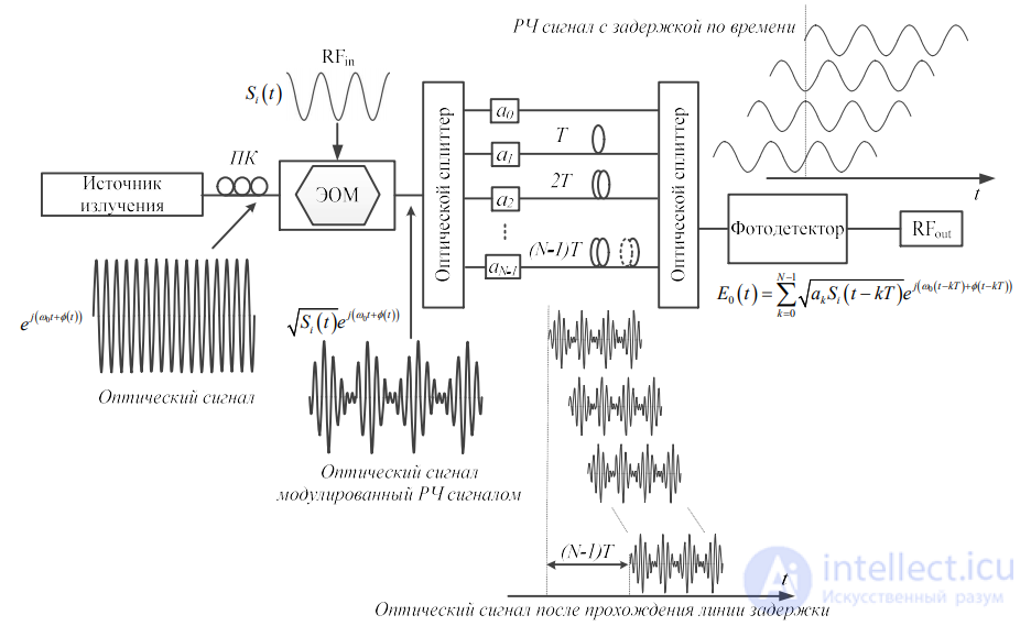
Figure 1.12 – Structure of a microwave photonic FIR filter using an example implementation with an optical signal time delay block
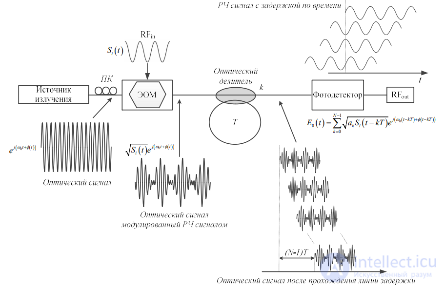
Figure 1.13 – Structure of a microwave photonic IIR filter using an example implementation with an optical signal time delay block in the form of an optical splitter
Thus, the radiation source in incoherent schemes of microwave photonic filters can be a set of lasers at different wavelengths, or it
can be a broadband radiation source with spectrum slicing. The key device in microwave photonic filters is the optical delay line
module, which may consist of an array of Bragg gratings, an arrayed waveguide prism, a chirped Bragg grating, or
a dispersive fiber. For an N-tap delay line of a microwave photonic FIR filter, the output microwave signal at the photodetector can be represented in the
following form:
 (1.1)
(1.1)
where b0, b1, b2, bN-1 are the filter weighting coefficients, T – the time delay between
adjacent filter taps. Applying the Fourier transform to (1.1) we obtain

The transfer function of the photonic filter is as follows:

The structures of incoherent FIR filters based on the listed methods of forming the optical delay module are given below.
Tuning of the spectral response of the filter is carried out by changing the magnitude of the time delay or by changing the wavelength
between the carriers. One of the drawbacks of using FBGs is the fact that they are not tunable. Therefore, a solution to the problem may be
the use of a tunable laser. The use of a chirped Bragg grating is also considered below. The tuning speed of such
lasers can reach the microsecond threshold. But, despite the fast response, some applications require a higher tuning
speed in the nanosecond range. This can be achieved using a comb radiation source, whose response speed reaches 40 ns [99].
As mentioned earlier, the weighting coefficients of a microwave photonic filter with optical delay lines operating in the incoherent regime will
take only positive values [24],[100]. Relying on signal processing theory, a microwave photonic filter with the aforementioned configuration
will operate as a low-pass filter. To overcome these limitations, optical delay lines were developed with the capability of
realizing negative and complex weighting coefficients, which in turn made it possible to achieve arbitrary filtering shapes in the incoherent regime.
Most of the first proposals for microwave photonic filters were based on passive structures consisting of separate optical
fibers [10],[12]. Therefore, these were non-reconfigurable filters, equivalent to conventional transversal digital filters.
Soon, new schemes appeared, similar to «lattice» filters with feedforward (non-recirculating) as well as «lattice» filters with
feedback (recirculating) structures, which were also borrowed from digital processing [101].
Transversal filters are similar in structure to their counterparts in the field of digital processing, where they were first used. The transfer
function of the microwave signal amplitude of an N-loop transversal photonic filter under the optimal polarization state for optical signals
is represented in the following form [102]:

where  – the photodiode responsivity, β – the dispersion parameter of the optical fiber, f – the frequency of the electrical signal, P – the impulse response of the
filter, Δτ – the time delay.
The term «lattice» refers to the interconnection structure formed by a cascade of sections compatible with the same basic topology, as shown in
Figure 1.14. These structures have two input ports and two output ports and take the form of feedforward filters (Figure 1.14 a) or feedback filters (Figure 1.14 b). These schemes use existing, widely developed theories for the design and synthesis of filters based on such
structures. These processors were capable of performing several operations, both in the time domain and in the frequency domain. They also allowed
integration to be carried out when the delay lines did not exceed a few centimeters.
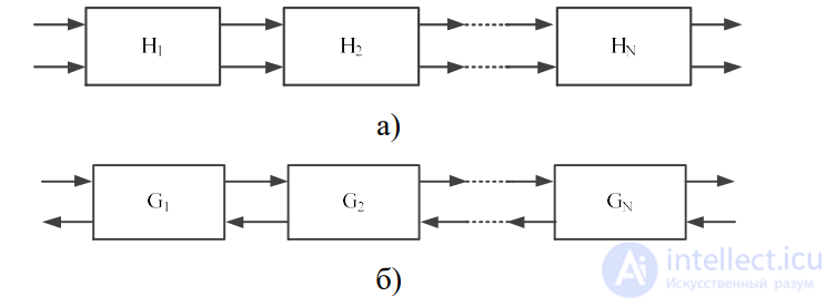
Figure 1.14 – Lattice filter structures a) feedforward b) feedback
Nevertheless, these systems have two main limitations, since they operate in the incoherent regime in order to eliminate the dependence of the phase
of the optical signal on environmental conditions (mechanical vibrations, temperature changes, etc.). First, optical sources with
a broad emission spectrum are required, so lasers with a small spectral emission width, which are usually used in optical communication
systems, cannot be applied. And second, a significant level of phase noise introduces a large delay due to the interference of optical signals.
This phase noise is, as a rule, the main source of noise limiting the signal-to-noise ratio in the system [103]. In addition, the first
filters did not have the capability for reconfiguration.
For these reasons, the physical properties of optical filters soon began to be used to improve performance and the ability
to change the passband frequencies (tunable) or change the shape of the frequency response (reconfigurable). Considering the similarity between the schemes of optical beamforming networks and transversal filters, some of the schemes shown in section 1.3 were adapted for use as microwave photonic filters.
The chromatic dispersion properties of optical fiber or any other dispersive medium can be used to implement
tunable filters [104]. Dispersion introduces a delay between optical carriers of different wavelengths, so that if these carriers
are modulated by an electrical signal and detected after passing through the dispersive medium, a transversal filter is obtained. Figure
1.15 shows the general scheme of filters of this type.
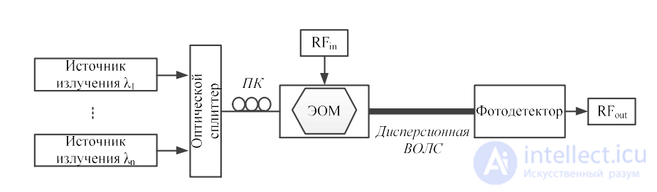
Figure 1.15 – Block diagram of a dispersion-based photonic filter
An alternative implementation is based on obtaining a multichannel optical signal from a source by slicing a broadband signal
(spectrum slicing) [105]. At the same time, the ability to tune the response is lost, but the cost of the filter decreases.
Dispersive fiber prism
Another similar system structure is presented in Figure 1.16, where the concept of a fiber prism is taken as the basis [106].
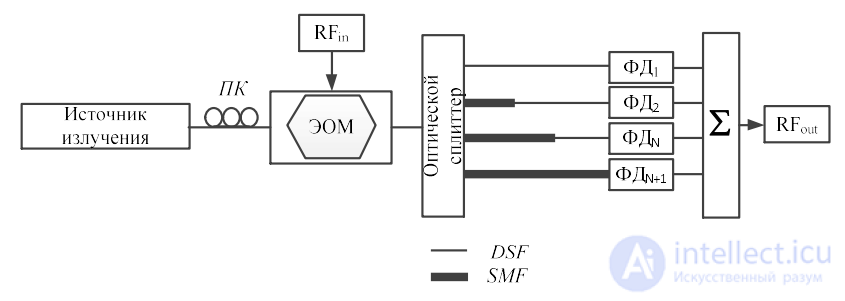
Figure 1.16 – Structure of a microwave photonic filter based on a fiber prism
Structures based on diffraction gratings. Optical gratings (for example, a Bragg grating) are a very versatile component that makes it possible to implement various types of microwave filters. The first group of filters based on these components uses
discrete diffraction gratings [107],[108].
Figure 1.17 shows the scheme of one of these structures in the case of a notch filter. The gratings are arranged in such a way that two
reflected optical signals return with a time delay, thus implementing a notch filter.
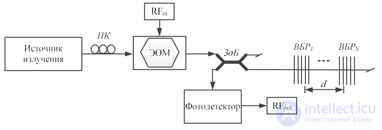
Figure 1.17 – Structure of a microwave photonic filter based on discrete diffraction gratings
These schemes have a drawback, since the time delay is achieved by changing the distance between the gratings, i.e. there is a minimum
delay (maximum value of the filtering period), determined by the minimum manufacturing resolution of the discrete
gratings. Thus, the minimum delay that can be achieved is about 10 ps. In addition, errors in the fabrication of
diffraction gratings lead to delay errors.
Schemes have also been proposed, similar to the one shown in Figure 1.18, based on discrete diffraction gratings that implement IIR filters (filters with an infinite impulse response) by replacing the splitter with an optical circulator [109]. Their structure is presented in Figure 1.18.
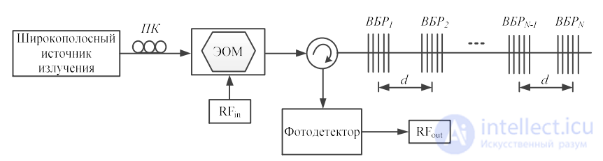
Figure 1.18 – Structure of a microwave photonic filter using a broadband radiation source and several optical Bragg gratings
In addition, there are structures of photonic filters where a radiation source with multiple optical carriers based on chirped
diffraction gratings is used (Figure 1.19). The diffraction gratings are chirped (dispersed), i.e. they introduce a delay that depends on the wavelength
of the incident radiation. The use of chirped gratings makes it possible to carry out continuous tuning (if the optical source allows
the frequency parameters of the radiation to be changed), and in addition it allows a smaller time delay to be obtained than when using an ensemble of discrete
gratings. Within such structures, a set of tunable lasers [102] can be used as the optical source, or one can take advantage of the nonlinearity property of an external modulator (an electro-optic Mach-Zehnder modulator, MZM, or an electro-absorption modulator, EAM) [110].
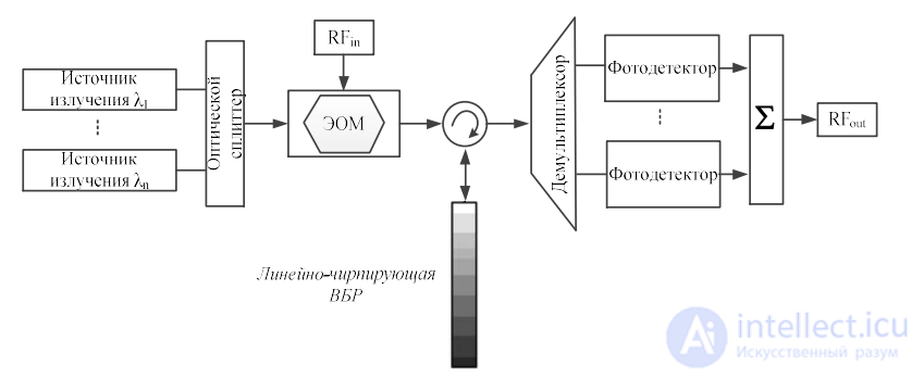
Figure 1.19 – Structure of a microwave photonic filter based on a linearly chirped FBG
Recently, chirped gratings with a variable dispersion index have been presented, and thereby with the ability to change the
time delay depending on each optical carrier. The most common method for achieving this effect consists of
thermal or mechanical action on the grating or the use of piezoelectric transducers. For example, in [111], to change the
magnitude of the dispersion of a diffraction grating from 300 to 900 ps/nm, a non-uniform magnetic field was used on a transducer that depends
on the applied voltage. Recently, a different approach has been proposed for implementing bandpass microwave photonic filters with negative
coefficients, based on the use of optical phase modulators [112]. The method is based on the conversion of phase modulation into
intensity modulation of the radiation in dispersive elements with additional dispersion, such as a linearly chirped FBG (LC FBG) with
additional chirp, by reflecting phase-modulated optical signals from an LC FBG with positive or negative chirp. Thus,
the microwave signals at the photodetector are obtained with or without a phase shift. An advantage of using a phase modulator is its
self-sufficiency, i.e. independence from external voltage sources, which means the absence of the voltage drift problem as in Mach-Zehnder modulators. The basic principle of operation of this kind of filter is depicted in Figure 1.20. The radio signal is fed to the optical phase modulator through the
input microwave port for phase modulation of the optical carriers entering the modulator through the optical port. Since the photodetector operates in the
envelope detection mode, if the phase-modulated signal is fed directly to the photodetector, the latter will recover only the DC component. This conclusion can also be reached based on the spectrum of the phase-modulated signal. Figure 1.20 shows the optical phase-modulated signal with sidebands that are in antiphase. When passing through a dispersive medium, the phases of the sidebands change, thereby leading to the conversion of phase modulation into intensity modulation of the radiation. In addition, depending on the sign of the chromatic dispersion, the detected radio signal may have a π phase shift, which will lead to the formation of negative coefficients.
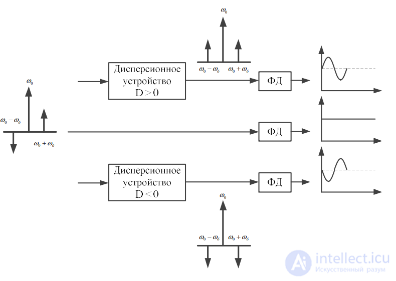
Figure 1.20 – Method of forming negative weighting coefficients of a microwave photonic filter based on the conversion of phase
modulation into intensity modulation of radiation
The structure of a filter operating according to the described technique is depicted in Figure 1.21.
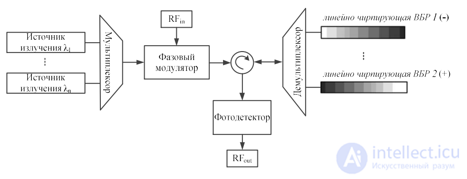
Figure 1.21 – Structure of a microwave photonic filter for forming negative coefficients, based on the method of phase modulation
conversion by means of devices with opposite dispersion values
Finally, the use of diffraction gratings together with a discrete optical amplifier for high-performance
IIR filters was proposed. Figure 1.22 demonstrates the scheme of the proposed structure. In this case, when the signal passes the first grating, part of the signal
is reflected. The remaining part of the signal is amplified by erbium-doped fiber and then fully reflected at the second grating. When the signal returns to the first diffraction grating, part of the signal is coupled out of the delay line, and part is reflected further into the active medium. By adjusting the gain of the active medium in such a way that the output signal maintains a constant amplitude and the structure does not re-emit, it is possible to obtain a large number of repetitions of the input signal with a constant time delay between them.
Thus, this structure makes it possible to achieve a high Q-factor value, presenting values in the range from 801 to 1 GHz [113].
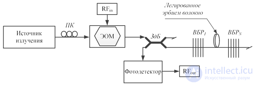
Figure 1.22 – Structure of a microwave photonic filter based on a pair of active discrete diffraction gratings
Structure based on arrayed waveguide gratings (AWG). AWG devices have also been used to implement microwave photonic
filters [114] in the same way as in structures for their direct purpose [115]. Figure 1.23 demonstrates the proposed structure.
It provides the ability to synthesize the required signal by a coarse method using delay lines obtained with the aid of the AWG, and finer
tuning by means of the structure depicted in the lower part of the scheme. This makes it possible to carry out continuous tuning of the output signal.
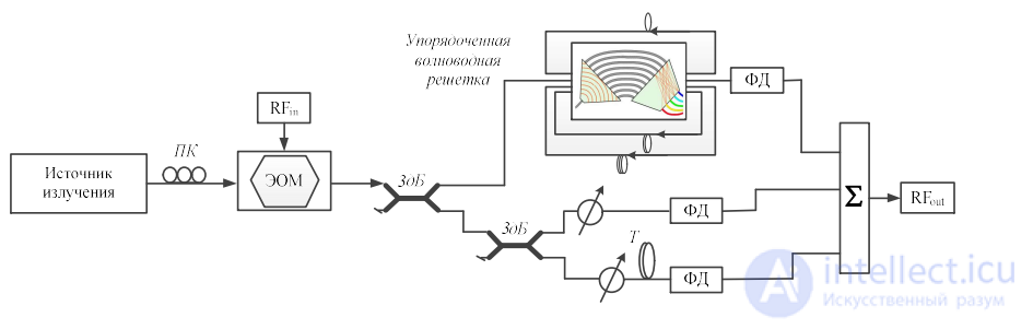
Figure 1.23 – Structure of a microwave photonic filter based on an arrayed waveguide grating

Comments