
Lecture
To solve the problem of coefficient positivity, various alternatives have been proposed. The first solution is based on the
electro-optical approach using separate detection schemes. An optical signal modulated by a radio signal passes through two taps of the filter. These taps serve as optical time delay lines with a difference T between them. The signal from the delay line is fed to a
differential detection module, which consists of two matched photodiodes. The detected microwave signals are then combined and subtracted in the electrical domain, which results in the formation of negative and positive weighting coefficients of the photonic filter. In this method, the negative coefficients are not formed directly in the optical domain, and the filter itself will not be fully optical, but will be considered a hybrid type. Figure 1.24 shows the general scheme of systems of this type.
A two-tap photonic microwave filter can be reconfigured into a multi-tap one if the single laser is replaced by a group of lasers and the 3 dB splitter
is replaced by a WDM demultiplexer. It has also been demonstrated that it is possible to implement an arbitrary filter as the difference of two positive filters [116]. This method was proposed in the filters of the first schemes based on recirculating structures, [10], [117].
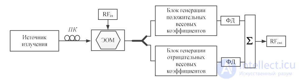
Figure 1.24 – Structure of a microwave photonic filter for forming negative filtering weighting coefficients based on differential detection
Subsequently, other solutions appeared based on the use of the physical principles of various optical devices to implement
negative inputs directly in the optical range, such as amplitude inversion of the modulated signal, which is obtained through
wavelength conversion via cross-gain modulation (XGM) and cross-phase modulation (XPM) in semiconductor amplifiers (semiconductor optical amplifier (SOA)) [118]. As shown in Figure 1.25, a tunable radiation source at wavelength λ1 is modulated by a microwave signal and then split into two components. One part is fed to the optical delay line, the other part is combined with the continuous signal of a DFB laser at a different wavelength and then fed into the semiconductor optical amplifier [119]. The continuous radiation of the DFB laser at wavelength λ2 is also modulated by the incoming radio signal, but with a phase shift of π compared to the other microwave signal, which results in the formation of negative weighting coefficients of the photonic filter. An optical bandpass filter is used to filter out the residual component of the λ1 signal. Then the microwave signal from the upper branch of the photonic filter and the phase-shifted microwave signal from the lower branch are combined and detected at the photodetector. In this way, a bandpass photonic microwave filter with one negative coefficient is formed. Detection at the photodiode can be considered incoherent, since the two optical carriers at different wavelengths are generated using two independent laser radiation sources. To avoid beating between the two wavelengths falling within the filter passband, the carriers must be chosen with a large frequency spacing. As mentioned earlier, it is possible to increase the number of coefficients by using several radiation sources and replacing the optical splitters with WDM multiplexers and demultiplexers.
This method has the advantage that phase inversion (negative coefficients) is achieved in the optical range, but it has
a limitation on the bandwidth of the electrical modulating signal, having a cross-modulation gain efficiency of a low-pass filter
[120].
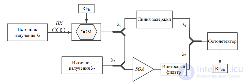
Figure 1.25 – Structure of a microwave photonic filter for forming negative coefficients, based on the cross-phase modulation effect
in semiconductor amplifiers
A similar method of forming negative coefficients using a Fabry-Perot interferometer and an FBG array is described below [121].
The filter structure is shown in Figure 1.26. As in the previous scheme, the microwave-modulated signal is split into two channels. The signal from the upper tap, passing through the optical delay line, is fed to the photodetector. In the lower channel, the signal is fed to a Fabry-Perot resonator. The Fabry-Perot laser diode operates with several longitudinal modes. One of the longitudinal modes is blocked by the input optical signal, while the others will experience cross-gain modulation. This process is similar to cross-gain modulation in an SOA; the signal modulating the free mode is phase-shifted. As a result, the negative coefficients are formed by the free modes. The time delay between adjacent free modes is introduced by the FBG array. The main drawback of the method is the mode competition regime at the laser output, which can lead to system instability. In addition, the spacing between modes must be large enough to avoid beating between two adjacent modes falling within the filter passband.
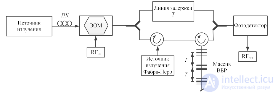
Figure 1.26 – Structure of a microwave photonic filter for forming negative coefficients, based on a Fabry-Perot interferometer
Other optical device effects proposing to implement negative coefficients by acting on the carrier in directly modulated DFB lasers [122] or cross-gain modulation of the emission spectrum in an SOA are described in [123].
One of the ways to form negative weighting coefficients of a photonic filter is a method based on the carrier depletion effect of a DFB laser [122]. The structure of the filter system is shown in Figure 1.27. Instead of using a multi-wavelength Fabry-Perot interferometer, a DFB laser operating in single-wavelength mode is used. The emitted wave of the DFB laser is blocked by the input optical radiation. Due to the carrier depletion effect, the microwave signal modulating the injection carrier is transferred to the emitting wavelength with a phase shift, which leads to the formation of negative coefficients. It is worth noting that the emitting wave of the DFB laser should not differ greatly in spectral characteristics from the injecting wave arriving at the photodetector through the FBG.
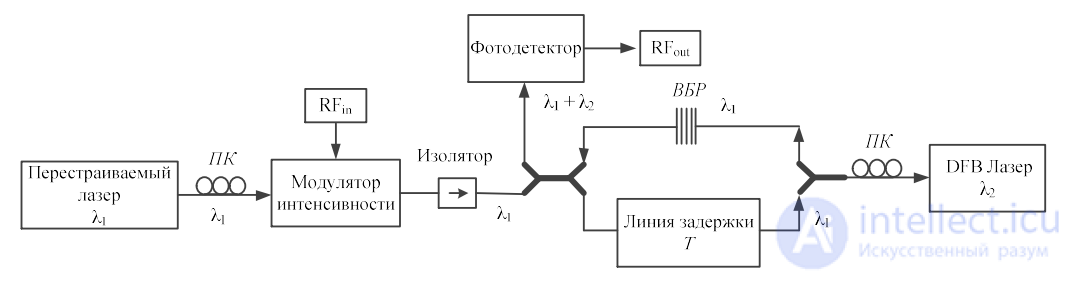
Figure 1.27 – Structure of a microwave photonic filter for forming negative coefficients, based on the carrier depletion effect of a DFB
laser
Another way of obtaining negative coefficients consists of «slicing» the spectrum of a broadband emitter using uniform
Bragg gratings [124]. In this scheme, the positive coefficients are obtained using tunable lasers in combination with EDFA amplifiers, and the
negative coefficients are obtained by creating nulls (notches) in the spectrum using diffraction gratings in «transmission» mode. The transmission
spectrum of the FBG is changed, which in turn is used to form negative coefficients. The positive coefficients
are formed using another multi-wavelength source, the output signal of which is combined with the filtered signal of the spontaneous emission source. The structure of the described two-tap photonic microwave filter is shown in Figure 1.28.
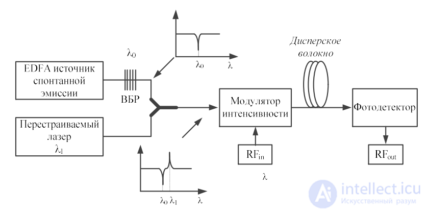
Figure 1.28 – Structure of a microwave photonic filter for forming negative coefficients, based on a spontaneous emission source
and a linear FBG
It should be mentioned the technique based on the use of the positive and negative linear part of the transfer function of
Mach-Zehnder electro-optical modulators [125], [126]. In Figure 1.29, in the inset, the transfer function of an electro-optical modulator is shown. To obtain positive and negative coefficients, two Mach-Zehnder modulators are used, each of which operates in a specific mode, which is marked in Figure 1.29 by separate voltage values. The operating point is chosen on the negative and positive sections of the modulator transfer function. When a microwave signal is applied to the two electro-optical modulators, the envelopes of the optical modulated signal complement each other. At the output of the photodetector, two complementary microwave signals are formed, which in turn create negative coefficients. The time delay between two adjacent taps is formed due to the chromatic dispersion effect in the dispersive device. To reconfigure this structure, laser arrays are used. To form positive or negative weighting coefficients, the corresponding wavelengths must be fed separately to both Mach-Zehnder modulators.
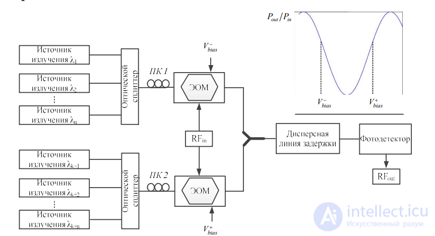
Figure 1.29 – Structure of a microwave photonic filter for forming negative coefficients, based on the transfer characteristic of a
Mach-Zehnder modulator
Structures of microwave filters based on polarization properties
A similar method is demonstrated in [127] using a single
Mach-Zehnder modulator. Taking into account the dependence of the transfer function of the
modulator on the wavelength of the incoming radiation, a precise DC voltage
will facilitate operation of the modulator on complementary sections of the
transfer characteristic, when the optical radiation is in the 1550 nm and
1310 nm transparency windows.
The structure of a microwave photonic filter can also be built on the basis of a
polarization modulator [128], [129]. A polarization modulator (PolM) –
is a device that transmits both transverse modes – the electric and
magnetic ones – but with opposite phase modulation indices. In
Figures 1.30 and 1.31, the operating principle of the PolM device and the scheme of the
photonic filter based on it are shown. Radiation from the source is fed to the PolM through a
polarization controller with a polarization direction of 45 degrees relative
to the principal axis of one of the PolMs. Due to polarization modulation
in the PolM, two in-phase radio signals carried on two optical carriers with the same wavelength but orthogonal polarization reach the output of the PolM. Then a polarization-maintaining optical fiber (PMF) is used
to form two different time delays.
Figure 1.31 shows a scheme for obtaining a larger number of delay intervals. For this, several optical radiation sources are used. An optical polarizer, the polarization angle of which is 45 degrees to the direction of the PolM axis, is connected to the output of the PolM. An in-phase or anti-phase microwave optical signal is obtained at the output of the optical polarizer by tuning the polarization of the input radiation to a value of 45 or 135 degrees toward one of the PolM axes. This, in turn, leads to the formation of positive or negative filter coefficients.
The time delays between adjacent taps (carriers) are formed due to the dispersive delay line, which can be represented as an optical fiber or a chirped FBG.
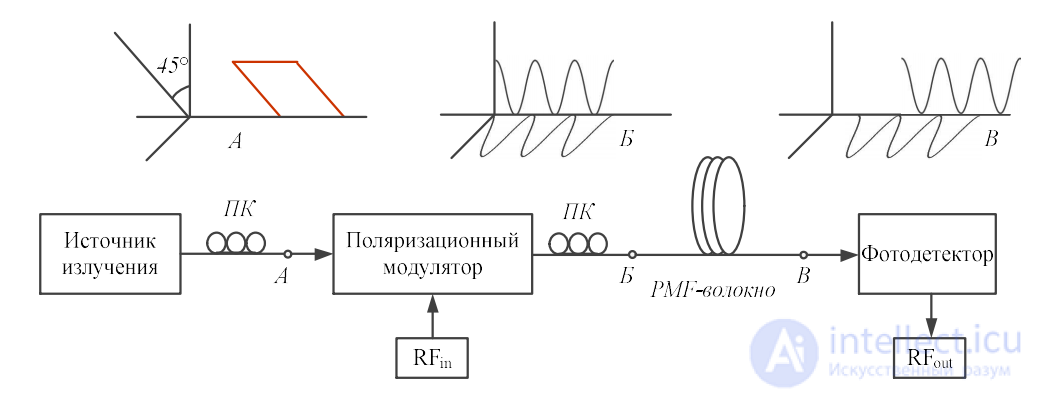
Figure 1.30 – Delay line of a microwave photonic filter based on a polarization modulator using a single wavelength and
time delays created by one or two sections of PMF fiber
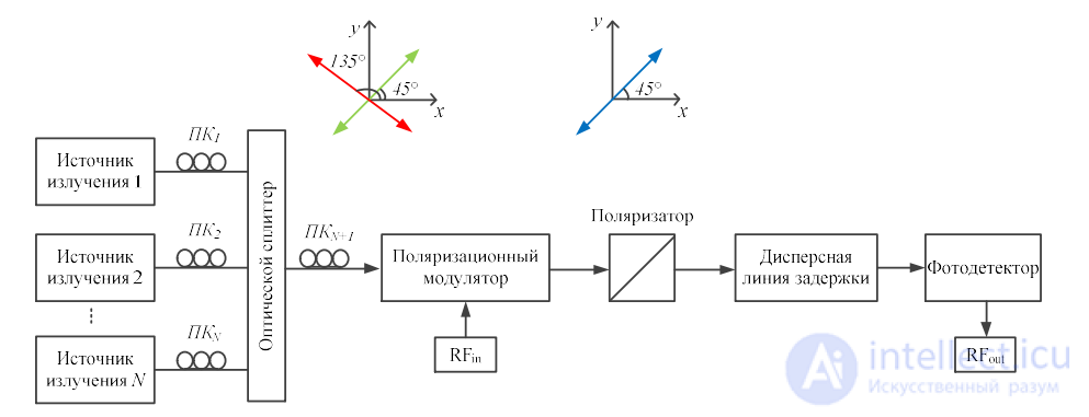
Figure 1.31 – Delay line of a microwave photonic filter based on a polarization modulator using N radiation sources and a dispersive delay line
Tuning of a microwave photonic filter with a delay line, as a rule,
occurs by adjusting the time delay. However, changing the
time delay will affect the change in the frequency characteristics of the
filter, such as the spectral periodicity. This will lead to a change in the
bandwidth at the -3 dB level, as well as a change in the frequency response of the filter
as a whole. For many applications it is preferable that only the
central passband or rejection frequency changes, leaving the frequency
response of the filter unchanged. The solution to this problem is the use of complex
weighting coefficients in microwave photonic filters with delay lines.
The transfer function of an N-tap photonic filter with complex
coefficients is as follows:
 (1.2)
(1.2)
where T – is the time delay between adjacent taps of the filter.
To keep the spectral characteristic of the filter unchanged during
its tuning, it is necessary that the phase differences between the filter taps
be matched, as can be seen from (1.2). Thus, the phase shift of each
tap must be tuned independently of one another. In [130], a structure of a two-tap microwave photonic filter with one complex
coefficient is described, which is built using three optical
attenuators and two microwave splitters. The transfer function of this filter
is as follows:
 (1.3)
(1.3)
where T – is a fixed value of the time delay.
By changing the phase φ, the transfer function of the filter will shift in the
longitudinal direction, but the shape of the spectral characteristic will
remain unchanged. Expression (1.3) can be rewritten in the following
form:
 (1.4)
(1.4)
where a = cos(φ), b = sin(φ).
As can be seen from (1.4), the transfer function contains only one complex coefficient -b/2j . The quantity
introduces a phase delay,
which does not affect the change of the spectrum.
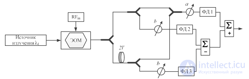
Figure 1.32 – Structure of a microwave photonic filter for forming complex coefficients, based on the use of optical attenuators and two microwave splitters
It should be noted that the presented structure of the photonic filter in
Figure 1.32 is a hybrid scheme, since the complex coefficients in it are
formed in the electrical domain after detection of the optical
signal.
A fully optical scheme for forming complex coefficients
is presented below in Figure 1.33. The complex coefficients in the scheme [131]
are formed due to the change in the phase of the radio signal, which in the structure of the photonic
filter is implemented through a combination of single-sideband modulation
(SSB) and stimulated Brillouin scattering (SBS).
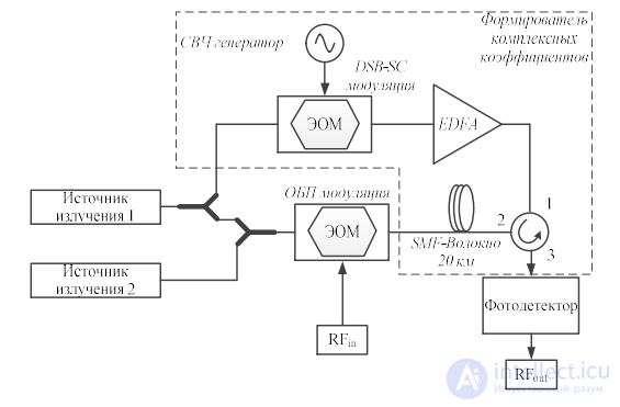
Figure 1.33 – Structure of a microwave photonic filter for forming complex coefficients, based on SSB modulation
As shown in the scheme, the microwave signal modulating the optical carrier
will have a phase shift if, when passing through the optical fiber,
the spectrum of the optical carrier or the sideband is suppressed in the gain spectrum
of the FBG [132]. The drawback of this scheme is the expensive and technically
complex reconfiguration capability. A simpler scheme is demonstrated
in Figure 1.34 [133]. The complex coefficients are formed due to
regulating the voltage of a broadband tunable optical
phase shifter of the microwave signal, built on two electro-optical
Mach-Zehnder modulators. The phase shift of the radio signal is carried out due to
a change in the voltage applied to the electro-optical modulators, which,
in turn, remains unchanged over the entire operating frequency range.
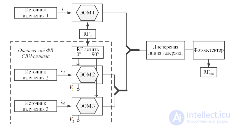
Figure 1.34 – Structure of a microwave photonic filter for forming complex coefficients, based on an optical radio signal phase shifter
The coherent mode in microwave photonic filters can be implemented using
a radiation source using only one wavelength. Due to
the fact that in coherent microwave photonic filters there are no delay lines,
optical interference will not negatively affect the stability
of the filter operation.
The general structure for building a coherent filter is shown in Figure 1.34. A narrowband laser signal is fed to a phase modulator, at the output
of which a carrier and two sidebands are formed.
It should be noted
that the sidebands are out of phase. Thus, upon
direct detection of the phase-modulated signal at the
photodetector, it is impossible to obtain the original radio signal, except for the
DC component, since the beating between the optical carrier and the lower
sideband will completely compensate the beating between
the optical carrier and the upper sideband. However, if
one of the sidebands is removed using a notch filter in
transmission, or a double bandpass filter is applied in reflection mode [134], for
example an FBG or a cascade of FBGs, then upon detection of the SSB amplitude-modulated signal at the photodetector, the required
radio signal is formed.
Figure 1.35 shows the scheme of a coherent photonic microwave filter, in
which an optical notch filter is used to remove one of the
sidebands of the phase-modulated signal, thereby implementing the
transition from a phase-modulated signal to an amplitude-modulated one with a single
sideband. It can be concluded that this scheme is equivalent to a microwave
filter whose passband is determined by the passband of the
optical notch filter (based on an FBG). The central frequency
is determined by the frequency difference between the optical carrier and the central
rejection frequency. Thus, the central frequency of the bandpass microwave
filter is tuned by changing the central frequency of the notch
filter or the wavelength of the radiation source. The spectral characteristic
of the filter during tuning remains unchanged. This gives a significant
advantage compared to incoherent structures of photonic filters,
in which the spectral shape changes during filter tuning, with the
exception of the schemes with complex coefficients that were considered
earlier.
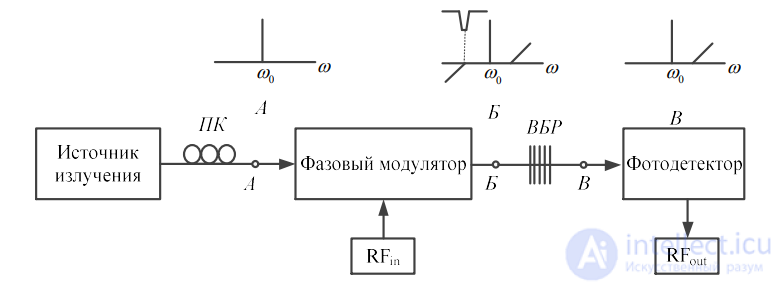
Figure 1.35 – Structure of a coherent microwave photonic filter, based on
the use of AM-SSB modulation.
A configuration of the considered scheme is possible using two FBGs
operating in reflection, one of which selects the optical carrier, and the
other transmits one of the sidebands. The drawback of such a method
is the wide passband, since a uniform FBG is used. The passband
of the microwave photonic filter is determined by the passband of the FBG
for selecting the sideband. The use of an optical ring resonator
[135] can reduce the bandwidth, but the selectivity of such a filter
will remain unacceptable for many applications.

Comments