
Lecture
The Pistolkors folded dipole — is a system of two parallel conductors (or systems of conductors) short-circuited at their ends and spaced a small distance apart relative to the wavelength. The generator is connected at the center of one of the conductors. When the length of these conductors is λ/2, a voltage node forms at the center of the other conductor, which makes it possible to ground the antenna element to the mast structure. An advantage of the folded dipole is its higher input impedance and the ability to adjust it by an appropriate choice of conductor radius. The typical input impedance of a half-wave Pistolkors dipole is 300 ohms, which makes it possible to feed it with a 300-ohm balanced line.
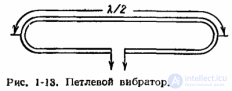
Simple half-wave dipoles (see Balanced half-wave dipole ) can be connected in the form of a stub, forming a folded dipole (Fig. 1-13). The radiation pattern of a folded dipole is almost indistinguishable from the radiation pattern of a simple dipole. The folded, or stub, dipole was proposed by A. A. Pistolkors in 1936.
When two simple dipoles are connected in parallel, the total inductance decreases in accordance with the formula
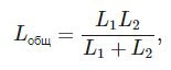
while the capacitance is summed. The L/C ratio, therefore, is smaller for the folded dipole, and its bandwidth is greater than that of the simple dipole.
To calculate the radiation resistance of the half-wave dipole we used the formula
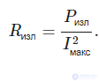
When two identical half-wave dipoles forming a folded dipole are connected in parallel, the antenna current, flowing through two branches, is divided into two parts. Thus, for the same radiated power, the antenna current of the folded dipole equals half the antenna current of the simple dipole; the radiation resistance of the folded dipole takes the form:
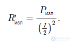
Thus, for the simple dipole we obtain:
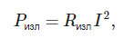
and for the folded dipole
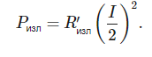
Since the radiated power is the same in both cases, it can be concluded that 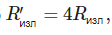 , i.e. the radiation resistance of the folded dipole is 4 times greater than the radiation resistance of the simple dipole and equals 240—280 ohms.
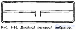
A variety of the simple folded dipole is the double folded dipole (Fig. 1-14).
In the case where the diameters of all conductors are the same, the antenna current in each dipole equals one third of the total antenna current. The input impedance of the double folded dipole is then 9 times greater than the input impedance of the simple dipole (about 540—630 ohms). Often, to change the input impedance at the antenna terminals, different dipole diameters are chosen.
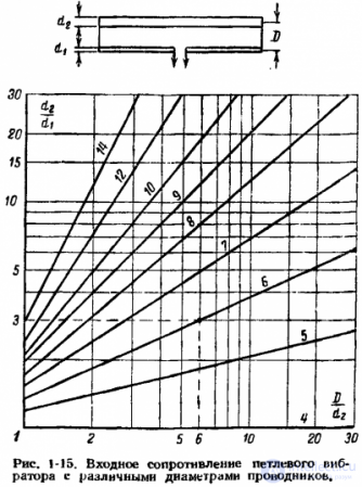
If the diameter of the upper, unbroken dipole d2 is greater than the diameter d1 of the lower dipole, then the input impedance increases compared with the input impedance of an ordinary folded dipole, and conversely, if the diameter d1 is greater than d2, then the input impedance decreases. This latter means of changing the input impedance is rarely used in practice, since for the purpose of matching the antenna to the feed line it is usually necessary to increase the input impedance.
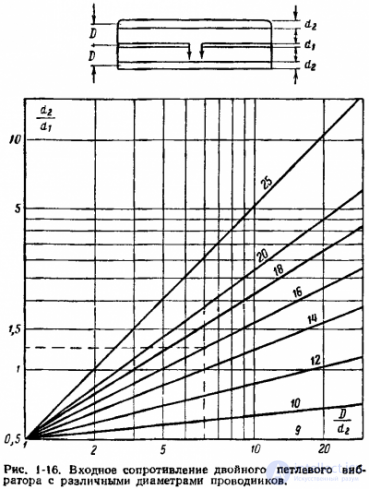
The input impedance of a folded dipole for various diameters (d2 > d1) is presented in the form of graphs in Fig. 1-15. For example, for d2/d1 = 3 and D/d2 = 6 the input impedance equals six times the input impedance of the half-wave dipole (360—420 ohms). In the same way, by choosing the diameter of the central conductor equal to or smaller than the diameters of the upper and lower conductors, one can change the input impedance of the double folded dipole. Fig. 1-16 shows the dependence of the input impedance of the double folded dipole for various ratios of diameters and distances between the conductors.
A half-wave balanced dipole antenna exhibits weakly pronounced bidirectional directivity, which makes it possible to orient the antenna toward the correspondent and thereby somewhat reduce the influence of external interference on the receiver input. There are two types of balanced dipoles: the split dipole and the Pistolkors folded dipole. The latter has the same radiation pattern as the split dipole, but its input impedance is 300 ohms. The high impedance facilitates matching the antenna to the feeder when using multi-element antennas, since increasing the number of elements in the antenna lowers its input impedance.
The advantages of Pistolkors half-wave dipole antennas include simplicity of construction, a wide operating band, low sensitivity to industrial interference, and the ability to vary the radiation pattern within small limits.
This type of antenna was proposed by the Russian scientist Alexander Pistolkors. The construction of the Pistolkors folded dipole is a system of two parallel linear dipoles forming a loop. These dipoles are placed a small distance apart relative to the wavelength and form a closed loop. One of the dipoles has a break at its center, to which the feeder is connected. The middle of the other dipole is a point of zero potential, which makes it possible to fasten the dipole at this point to a metal mast without insulation. An advantage of the folded dipole is its higher input impedance and the ability to adjust it by an appropriate choice of conductor radius.
The typical input impedance of a half-wave Pistolkors dipole is 300 ohms, which makes it possible to feed it with a 300-ohm balanced line.

Comments