
Lecture
A patch antenna (from the English patch — a patch of material; in the Russian-language literature the term strip antenna is used) — is a type of weakly directional antenna for the UHF and microwave bands. A patch antenna consists of a thin flat metal plate (the "patch") located at a small distance (0.01…0.1λ) parallel to a flat metal screen. The gap between the patch and the screen may be filled with a layer of dielectric (ε = 2.5…10, tanδ = 10-3…10-2), and the antenna itself may be manufactured using printed circuit board technology (a microstrip or printed patch antenna). As a rule, the patch has a rectangular shape, with the distance between the radiating sides of the rectangle (i.e. the length of the non-radiating sides) close to half of the operating wavelength (accounting for ε).
Feeding is accomplished by a pin passing through the screen (for example, being a continuation of the signal conductor of a coaxial line) and offset from the center of the rectangle toward one of its radiating sides, or by a microstrip line whose signal conductor lies in the plane of the patch and approaches one of its radiating sides. In both cases the exciting conductors are electrically connected to the patch. An electrodynamic method of exciting the patch through a slot in the screen is also known. The polarization of the radiated electromagnetic wave in the direction of the normal to the patch is close to linear; known engineering solutions make it possible to also form a wave with circular polarization. A patch antenna of the simplest design is narrowband (<5 %), but special engineering solutions make it possible to widen the operating frequency band to 50 % or more, or to build multiband antennas.
The operating principle of a patch antenna is based on the resonance of the TM10 mode in the volume beneath the patch, the excitation of an electric field in the gaps along two opposite sides of the patch, which can be regarded as a co-directional flow of an equivalent magnetic current along each of these sides, and the excitation of an electromagnetic wave by these two segments of magnetic current. The operation of a patch antenna is analogous to the operation of a pair of in-phase parallel slot antennas spaced at a small (< λ/2) distance. Cross-polarized radiation in a patch antenna of traditional design is caused by the radiation of the magnetic current along the sides of the patch transverse to the main sides (i.e. those creating the radiation at the main polarization), including via the TM02 mode. This radiation is compensated by interference only in the E and H planes and reaches a maximum (—10 dB) in the diagonal planes.
Many varieties of patch antennas are known, differing in the method of excitation, the presence of matching elements (slots in the patch and others), the shape of the patches (rectangular, circular and others), their number in a single radiator (one or several, as a rule no more than three), their relative arrangement (coplanar, stacked) and the method of mutual coupling (electrical connection, electrodynamic coupling) and so on, solving specific tasks and differing in their technical characteristics. Patch antennas are manufacturable, simple to fabricate, cheap, and convenient for use as the radiating element of an antenna array, including in airborne radar antennas, GSM mobile communication base stations, flat antennas for receiving satellite television and others. In the VHF band a patch antenna may be manufactured as a separate device protected from external influences. The section of the housing of such a device opposite the patch is made radio-transparent.
A microstrip antenna (printed antenna, patch antenna, English Patch-antenna) is a narrowband antenna with a wide beam. Physically, such an antenna has a two-dimensional geometry. The main element of a patch antenna is a flat metal plate (the «patch», from the English patch). In the simplest microstrip antenna, half-wavelength plates are used, so that the metal surface of these plates acts as a resonator similar to a half-wave dipole. A microstrip antenna is usually manufactured by placing a metal plate of a given shape on an insulating layer of dielectric, similar to how printed circuit boards are made, with the difference that on the side of the dielectric opposite the plate a continuous metal substrate is installed, which forms the grounding surface. Such a design is simple to develop and inexpensive to manufacture. Some patch antennas do not use a continuous layer of dielectric, and instead the metal plates are installed above a metal substrate on dielectric spacers. The resulting structure is less rugged, but has a wider operating frequency band. Microstrip antennas are designed for frequencies from the UHF band up to 100 GHz.
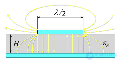
Figure 1. Cross-sectional view of a simple patch antenna
Patch antennas mainly use plates of square, rectangular, circular or elliptical shape. However, any other solid (continuous) shape may also be used. Patch antennas are characterized by mechanical strength and can have a shape conforming to the curved surface of a vehicle. Such antennas are installed on the external surfaces of aircraft or spacecraft, and are also built into mobile radio communication devices. They possess high polarization selectivity and can be used with several feed points.

Figure 2. Microstrip antenna array of an X-band marine navigation FMCW radar
Microstrip antennas appeared in the 1980s. Initially it was a military development, so cost was not of decisive importance. In the 1990s this technology was also adapted for communication devices as a low-cost technology. However, the efficiency of microstrip arrays remained lower than that of reflector antennas. Below is a comparison of the main properties of antennas of these two types.
The simplest patch antenna is a square patch with a side equal to half of the wavelength, located above a larger ground plate. The larger the ground plate, the better the directivity of the antenna and the larger its dimensions. Often the ground plate is made only slightly larger than the patch. The current flows in the same direction as the feed, so that the vector potential and, accordingly, the electric field follow the current, as indicated in the figure by the arrow E. A simple patch antenna radiates a linearly polarized wave. Its radiation can be regarded as the radiation of two slots at the edges of the antenna or, equivalently, as the result of the flow of current in the patch and the ground plate.
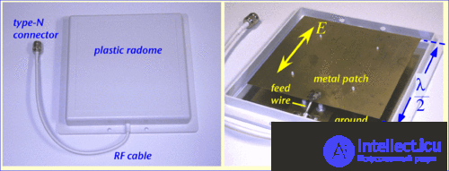
The gain of a rectangular microstrip patch antenna with an air dielectric can be roughly estimated as follows. Since the length of the patch is equal to half of the wavelength, the patch can be represented as a half-wave dipole, which gives about 2 dB of gain along the vertical axis of the patch. If the patch is square, it can be regarded as two half-wave dipoles spaced a quarter of a wavelength apart, which gives another 2-3 dB of gain. The ground plate shields the radiation from the back side of the antenna and reduces the volume-averaged radiated power by half, which gives another 2-3 dB. Adding it all together, we obtain a patch antenna gain equal to 7-9 dB, which agrees well with more rigorous estimates.
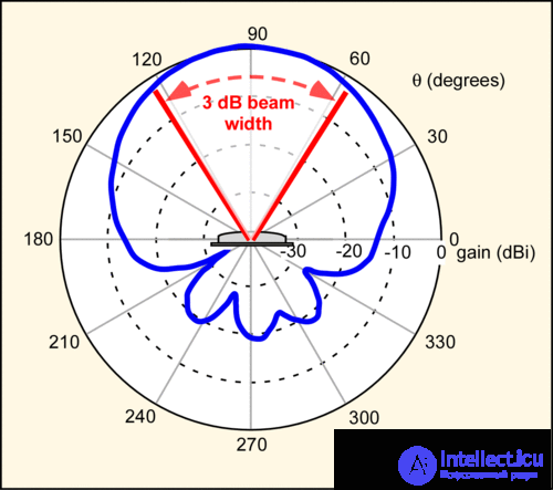
A typical radiation pattern of a linearly polarized patch antenna at 900 MHz is shown below. The figure shows a cross-section in the horizontal plane. The radiation pattern in the vertical plane is similar, but not identical. The scale of the graph is logarithmic, so that, for example, the power radiated in the direction of 180° (90° to the left of the vertical axis) is 15 dB less than the power of the main lobe. The width of the main lobe is about 65°, the gain in the direction of the beam is 9 dBi. An infinitely large ground plate completely shields the rear hemisphere (from 180° to 360°); however, the ground plate of a real antenna has finite dimensions. Therefore the radiated power in the backward direction (the back lobe of the radiation pattern) is only about 20 dB less than the radiated power of the main lobe.
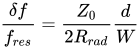
The bandwidth of a patch antenna strongly depends on the distance between the patch and the ground. The closer the patch is to the ground, the less energy is radiated and the more is stored in the capacitance and inductance, and the higher the Q-factor of the antenna. Roughly, the bandwidth of the antenna can be estimated by the formula:
 ,
,
where  — is the distance from the patch to the ground,
  — is the width of the patch (usually half of the wavelength),
  — is the impedance of the air gap between the patch and the ground, and
  — is the radiation resistance of the antenna. The relative bandwidth of the antenna depends linearly on its thickness. A characteristic value of the impedance of the air gap is 377 ohms, and of the radiation resistance is 150 ohms, which makes it possible to simplify the formula[citation needed for 3062 days]:
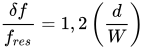
For a square patch at 900 MHz, will be approximately 16 cm. An antenna thickness of 1.6 cm will give a relative bandwidth of 1.2(1.6/16) ≈ 12 %, or 120 MHz.
Patch antennas are easy to manufacture by the printed method. In this case they turn out somewhat more compact, but since their thickness is smaller, the bandwidth is also reduced due to the increase in the Q-factor. Thus, the bandwidth of the antenna is inversely proportional to the square root of the effective dielectric constant of the substrate. It is also evident that the bandwidth widens with increasing thickness of the substrate. The characteristic bandwidth of a printed patch antenna is a few percent. Often the ground plate of real patch antennas is only slightly larger than the patch, which also reduces efficiency. The method of exciting the antenna also affects its bandwidth.
Rectangular (non-square) antennas can be used to obtain a fan-shaped radiation pattern in which the widths of the vertical and horizontal lobes differ substantially. Besides square patches, circular or polygonal patches may also be used. Calculating the radiating characteristics of such antennas is considerably more complex.
It is possible to make a patch antenna with circular polarization. One way is to feed an ordinary square patch from two points 90° out of phase. In this case, when, say, the vertical current is at a maximum, the horizontal current is 0. A quarter cycle later, the situation is reversed and the field becomes horizontal. The radiated field will rotate in time, so its polarization will be circular. By varying the magnitude of the phase shift between the two feed points, any polarization can be achieved, from linear to circular. Another way to achieve circular polarization is to feed a square patch from a single point, but cut an asymmetric slot or opening of another shape into it in order to shift the direction of the current. It is worth noting that although disc patches can also be used for such a technique, they do not necessarily have circular polarization. For example, a symmetric disc patch fed at a single point radiates linearly polarized waves. Finally, if an almost square patch, whose length is slightly greater and whose width is slightly less than half of the wavelength, is fed at a corner point, then the polarization of its radiation will be circular.
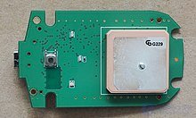
A microstrip antenna array for a satellite television receiver.
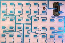
Diagram of the feed structure of a microstrip antenna array.
In telecommunications, a microstrip antenna (also known as a printed antenna) usually means an antenna fabricated using photolithographic techniques on a printed circuit board (PCB). It is a kind of internal antenna. They are mainly used at microwave frequencies. An individual microstrip antenna consists of a patch of metal foil of various shapes (a patch antenna) on the surface of a printed circuit board (PCB) with a metal foil ground plane on the other side of the board. Most microstrip antennas consist of several patches in a two-dimensional array. The antenna is usually connected to a transmitter or receiver via foil microstrip transmission lines. A radio-frequency current is applied (or, in receiving antennas, the received signal is produced) between the antenna and the ground layer. Microstrip antennas have become very popular in recent decades due to their thin flat profile, which can be built into the surfaces of consumer products, aircraft and missiles; the ease of their fabrication using printed circuit board technology; the ease of integrating the antenna on the same board with the rest of the circuit; and the possibility of adding active devices, such as microwave integrated circuits, to the antenna itself to make active antennas
The most common type of microstrip antenna is the patch antenna. Antennas using patches as constituent elements in an array are also possible. A patch antenna is a narrowband, wide-beam antenna fabricated by etching the pattern of the antenna element onto a metal trace attached to an insulating dielectric substrate, such as a printed circuit board, with a continuous metal layer attached to the opposite side of the substrate, which forms the ground plane. Common shapes of microstrip antennas are square, rectangular, circular and elliptical, but any continuous shape is possible. Some patch antennas do not use a dielectric substrate, but are instead made of a metal overlay installed above a ground layer using dielectric spacers; as a result the structure is less rugged, but has a wider bandwidth. Because such antennas have a very low profile, possess mechanical strength and can have a shape conforming to the curves of a vehicle's skin, they are often installed on the outside of aircraft and spacecraft or built into mobile radio communication devices.
Microstrip antennas are relatively inexpensive to manufacture and design due to their simple two-dimensional physical geometry. They are usually used at UHF and higher frequencies, since the size of the antenna is directly related to the wavelength at the resonant frequency. A single patch antenna provides a maximum directional gain of about 6-9 dBi. It is relatively easy to print an array of patches on a single (large) substrate using lithographic methods. Patch arrays can provide much greater gain than a single patch at little additional cost; matching and phase adjustment can be performed using printed microstrip feed structures, again in the same operations that form the radiating patches. The ability to create high-gain arrays in a low-profile antenna is one of the reasons that patch arrays are widespread in aircraft and other military applications.
Such a matrix of patch antennas is a simple way to make a phased array of antennas with the capability of dynamic beam forming.
An advantage inherent to patch antennas is the ability to have polarization diversity. Patch antennas can be easily constructed with vertical, horizontal, right-hand circular (RHCP) or left-hand circular (LHCP) polarization using multiple feed points or a single feed point with asymmetric patch structures. This unique property allows patch antennas to be used in many types of communication channels that may have differing requirements.
The most commonly used microstrip antenna is the rectangular patch, which looks like a truncated microstrip transmission line. It is approximately half of a wavelength. When air is used as the dielectric substrate, the length of the rectangular microstrip antenna is approximately half of the wavelength in free space. Since the antenna is loaded with a dielectric as the substrate, the length of the antenna decreases as the relative dielectric constant of the substrate increases. The resonant length of the antenna is slightly shorter due to the extended electrical «fringing fields», which slightly increase the electrical length of the antenna. An early model of the microstrip antenna is a patch of microstrip transmission line with equivalent loads at both ends to represent the radiation losses.
The dielectric loading of a microstrip antenna affects both the radiation pattern and the impedance bandwidth. As the dielectric constant of the substrate increases, the bandwidth of the antenna decreases, which increases the Q-factor of the antenna and, therefore, reduces the impedance bandwidth. This relationship is not immediately traceable when using the transmission line model of the antenna, but becomes evident when using the cavity model, which was presented in 1973 by Ito and Mittra. The radiation of a rectangular microstrip antenna can be understood as a pair of equivalent slots. These slots act as an array and have the highest directivity when the antenna has an air dielectric, and it decreases when it is replaced by a dielectric substrate with an increasing relative dielectric constant.
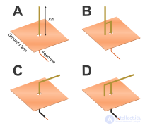
A half-wave rectangular microstrip antenna has a virtual shorting plane in its center. It can be replaced by a physical shorting plane to create a quarter-wave microstrip antenna. This is sometimes called a half-patch. The antenna has only one radiating edge (equivalent slot), which reduces the directivity / gain of the antenna. The impedance bandwidth is slightly lower than that of the full half-wave patch, since the coupling between the radiating edges is eliminated.
Another type of patch antenna is the planar inverted-F antenna (PIFA). The PIFA is widely used in cellular telephones (mobile phones) as a built-in structure. These antennas are derivatives of the quarter-wave half-patch antenna. The length of the shorting plane of the half-patch is reduced, which lowers the resonant frequency. It has a low profile and acceptable SAR characteristics. This antenna resembles an inverted letter F, which explains the name PIFA. It is popular as a compact antenna with an omnidirectional radiation pattern.
Often PIFA antennas have several branches for resonance in various cellular communication bands. Some phones use grounded parasitic elements to improve the characteristics of the radiation band.
The folded inverted conformal antenna (FICA) has some advantages over the PIFA, since it allows for better reuse of volume.
The Defected Ground Structure (DGS) integrated microstrip patch has been popular for a multitude of purposes. This method introduces a limited number of small-sized slots, called «defects», in the ground plane beneath the patch, and is potentially capable of improving its properties in both the far and near field. This was conceived and presented in 2005 by Debatosh Guha and a group to control cross-polarized radiation without additional components, volume, weight or cost. The technique is advanced enough to reduce cross-polarized radiation even in the diagonal planes of a microstrip patch. The DGS method is equally effective for reducing mutual coupling in large arrays of microstrips and, therefore, for mitigating the problem of radar beam scan blindness. The DGS method has proven very attractive for airborne applications.


Comments