
Lecture
A polarizer — a device designed to produce fully or partially polarized optical radiation from radiation with an arbitrary polarization state. According to the type of polarization obtained by means of polarizers, they are divided into linear, circular, and the rarer elliptical types. Linear polarizers make it possible to obtain plane-polarized light, circular ones produce circularly polarized light, and elliptical ones produce elliptically polarized light with a predetermined type of ellipse.
Linear polarizers are based on the use of one of three physical phenomena. One of them is birefringence, another is linear dichroism, and the third is the polarization of light that occurs upon reflection at the interfaces between media. Circular polarizers usually consist of a combination of a linear polarizer and a quarter-wave plate (an optical compensator).
Polarizers are used in the study of mechanical stress distributions in transparent objects by means of polarized light, in the study of the structure of substances, in saccharimetry, and especially in crystal optics. They are widely used in photographic polarizing filters and in astronomy.
Polarizers serve to change the direction (polarization) of the oscillations of electromagnetic waves. Most often they convert a linearly polarized wave into a circularly polarized wave, and vice versa.
Polarization selectors are designed to separate waves with perpendicular (orthogonal) oscillation directions.
A septum polarizer combines the functions of both a polarizer and a polarization selector.
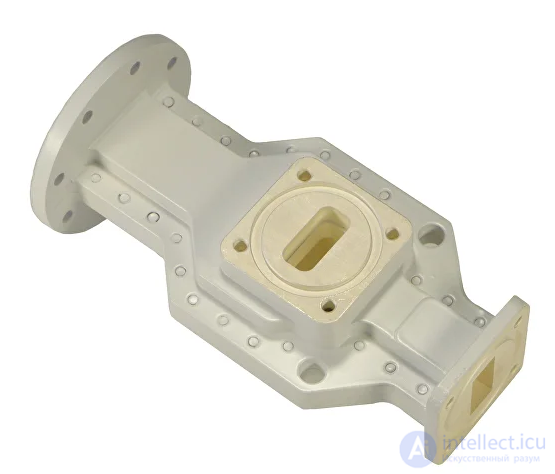
polarization selector - A device designed to combine or separate waves with orthogonal polarization.
Structurally, it is made in the form of a tee consisting of sections of circular and rectangular cross-section waveguides.
The coupling between the circular and rectangular waveguides is provided through longitudinal slots arranged perpendicular to each other (Fig. 4). The separation of the electric field vectors E1 and E2 is carried out by means of a reflecting plate. The polarization isolation of such a selector is 30-40 dB.
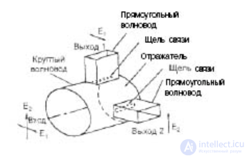
Fig. 4. Polarization selector
Example
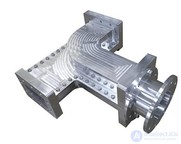
Fig. 1 C-band septum polarizer
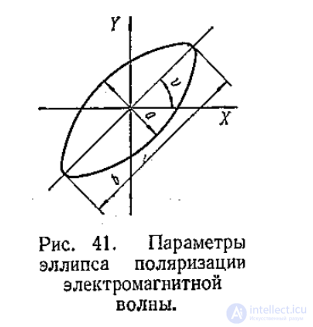
Polarization selection is the extraction of a useful signal against a background of active interference or interfering reflections based on the difference in their polarization structure. The polarization structure of an electromagnetic wave is determined by the following parameters (Fig. 41): the angle of spatial orientation of the polarization ellipse  ; the ellipticity ratio of the signal
  ; the direction of rotation of the electric field intensity vector.
By choosing the specified parameters (including their static characteristics), as well as by correspondingly varying them, it is possible to achieve both a significant attenuation of the effect of interference of any origin, but with stationary characteristics of the polarization structure, and an improvement in the technical performance of the radio system.
In particular, with regular rotation of the electric field intensity vector (the signal's polarization plane), the angular fluctuations of the signal reflected from an extended target are significantly reduced, which means that tracking accuracy is improved. Polarization selection is used for protection against both active and passive interference (hydrometeors, false targets, etc.). A polarization selector makes it possible to distinguish signals from targets of complex configuration against a background of false targets (corner reflectors, lens reflectors, etc.). By choosing the appropriate signal polarization parameters, it is possible to improve the observability of targets against a background of reflections from the ground or a water surface.
Polarization selection can be used in combination with other selection methods.
A distinction is made between polarization selection of oscillations with constant parameters of the polarization structure and polarization-modulated oscillations. In the first case, the selection device extracts oscillations of a specific type of polarization, suppressing oscillations with a different polarization. In the second case, the device receives oscillations that possess a specific polarization spectrum.
The principle of polarization selection is as follows. The antenna or polarization receiver is tuned to receive a signal of a specific polarization: linear, circular, or, in the general case, elliptical. Tuning to an adjustable polarization is possible. Interference is attenuated to the maximum extent if the polarization of the antenna or receiver is orthogonal to the polarization of the interference: for vertical interference polarization – horizontal; for circular polarization – circular with the opposite rotation of the received field; for an elliptically polarized wave, an elliptically polarized oscillation is also orthogonal, but with the axes of the polarization ellipse shifted by 900. Since the polarization of signals reflected from real targets is random and, in the general case, does not coincide with the polarization of the interference, the interference can be attenuated more than the signal.
At present, the following methods of polarization selection are used: the use of signals and antennas with circular and elliptical polarization; the use of signals with random polarization parameters; the use of antenna systems with hidden polarization for reception and a low level of cross-polarization lobes.
Let us consider the improvement in the observability of radar signals when using an antenna with elliptical polarization.
When receiving signals on an elliptically polarized antenna, the electromotive force induced in it depends on the polarization parameters of the incident wave:

where E – is the EMF induced by the signal in the antenna; k – is a constant coefficient; ke.a. 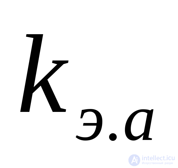 - is the ellipticity ratio of the antenna (of the wave radiated by the receiving antenna in transmit mode); ke.s. - is the ellipticity ratio of the field of the received signal;ψ - is the angle between the major axes of the polarization ellipses of the antenna and the incident wave
  . The "+" sign is taken when the fields rotate in the same direction, and the "-" sign when they rotate in opposite directions.
In the case of matching the antenna to the polarization structure of the incident wave 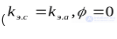 , identical rotation of the electric field vectors)
  .
.
With orthogonal arrangement of the ellipse axes  , and opposite rotation of the electric field vectors of the antenna radiation and the incident wave field, we obtain complete suppression of the received signal (E=0). In the case of radiating elliptically polarized waves and matching the antenna-waveguide path to the polarization parameters of the useful signal, it is possible (when the polarization structures of the signal and the interference differ) to increase the signal-to-interference ratio at the antenna output compared with the ratio at the input.
The ratio of the signal power to the interference power at the receiver input for equal signal and interference powers at the antenna aperture.

where  - is the ellipticity ratio of the interference field;
  is the angle between the major axes of the polarization ellipses of the signal and the interference.
The greatest influence on the effectiveness of selection is exerted by the difference in the direction of rotation of the electric field vectors, and the closer
the coefficients  are to unity, the greater this influence. Differences in the ellipticity ratios and in the spatial position of the ellipse axes can be effectively used only at small values of
  .
.
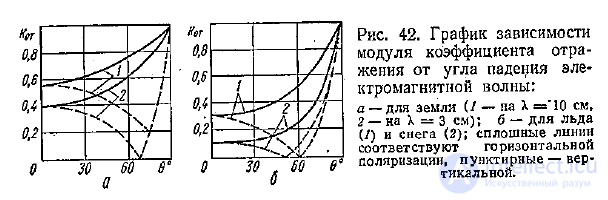
Let us consider the use of polarization selection to combat interfering reflections from the ground and hydrometeors. The intensity of interfering reflections from the ground depends to a large extent on the polarization of the radiation (Fig. 42). By choosing the polarization of the useful signal, at certain values of the illumination angle Θ it is possible to ensure maximum attenuation of reflections from precipitation. In radars with linear polarization, this is explained by the difference in the polarizations of the radio waves reflected from targets and from precipitation. Reflections from hydrometeors have the same polarization as the incident wave. Reflections from real targets, in particular an aircraft, however, have a component orthogonal to the incident wave. Reception of this component makes it possible to significantly attenuate the interfering reflections. The following methods of creating nonreciprocal antennas with linear polarization are possible:
two linear-polarization antennas with mutually orthogonal effective-height vectors, one of which operates in transmit mode and the second – in receive mode;
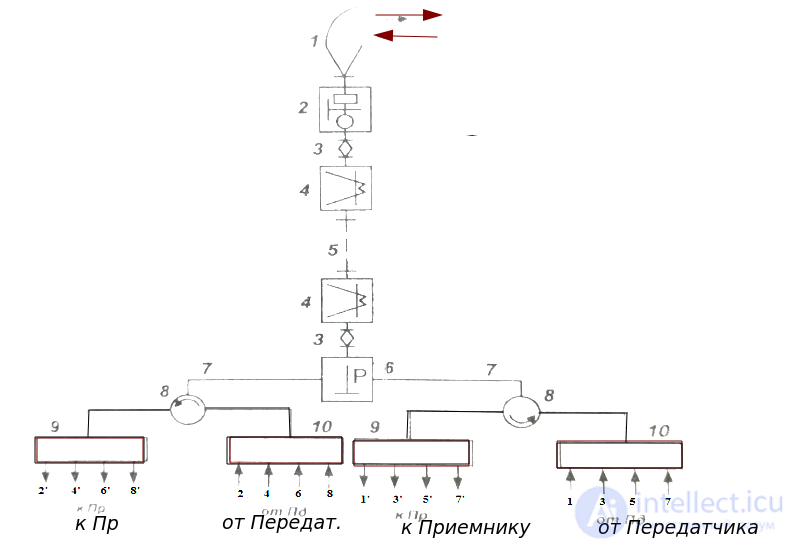
one antenna with switching of the receive and transmit channels connected to the antenna through a polarization splitter;
one antenna with a nonreciprocal element in the waveguide path.
When using radio waves with circular polarization, the direction of rotation of the polarization plane of the wave reflected from hydrometeors reverses. The energy reflected from an aircraft is polarized elliptically while retaining the direction of rotation of the polarization plane, and is therefore received by the antenna. Thus, by matching the antenna polarization to the polarization of the input signal, the interfering reflections can be significantly attenuated.
The suppression coefficient of signals reflected by various atmospheric formations, for two types of antenna polarization, is given in Table 6.
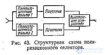
The block diagram of a polarization selector is shown in Fig. 43. The orthogonal components of the electromagnetic wave are extracted by the corresponding polarization filters 1 and 2 and, after amplification by identical receivers, are fed to a subtracting device. Since  the interference is compensated more fully than the signal.
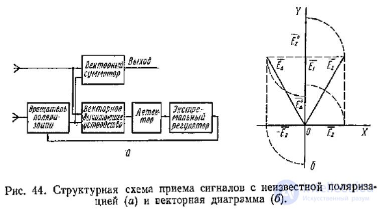
By using the reception of signals with an antenna of orthogonal polarization, it is possible to achieve an increase in the energy of the received signal when its polarization is unknown, and to improve the signal-to-interference ratio. A block diagram that implements this task is shown in Fig. 44, a. Signals of orthogonal polarization received by two antennas are fed to devices that form the vector sum and the vector difference (Fig. 44, b). An extremal controller rotates the polarization plane of the signal received by one of the antennas until a minimum of the vector difference is obtained  . In this case, the vector sum of the signals acquires its maximum value
  and is used as the output signal.
One type of organized polarization interference is cross-polarization interference. The effectiveness of such interference depends on the antenna's ability to receive an electromagnetic wave with a polarization orthogonal to the operating one. Therefore, one of the methods of combating such interference, along with the use of antennas with a low level of cross-polarization components, is the use of highly selective polarization filters.
Another method of combating cross-polarization interference is the use of receiving antennas with polarization diversity. If a channel that receives the more powerful signal, i.e., the polarization interference, is used in this case, then this interference will play the role of an illumination signal for the interference source (target).
In conclusion, we note that the implementation of polarization selectors is possible by fairly simple technical means, in particular, by using phased-array antennas, ferrite devices, etc.

Comments