
Lecture
An antenna is an array of conductors ( elements ) electrically connected to a receiver or transmitter. Antennas can be designed to transmit and receive radio waves equally in all horizontal directions ( omnidirectional antennas ) or, preferably, in a specific direction ( directional antennas, or high-gain antennas, or «beam» antennas). An antenna may include components not connected to the transmitter, such as parabolic reflectors , horns, or parasitic elements , which serve to shape the radio waves into a beam or another desired radiation pattern.
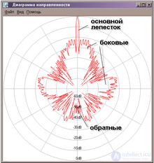
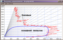
The radiation pattern (of an antenna) — is a graphical representation of the dependence of the antenna gain or the antenna directivity on the direction of the antenna in a given plane . The term «radiation pattern» also applies to other devices that emit signals of various kinds, for example loudspeaker systems. The radiation pattern of an antenna also determines the position and size of the antenna's blind zone.
The field radiation pattern of an antenna is often referred to as the dependence of the magnitude of the complex amplitude of the field-strength vector  of the electric component of the electromagnetic field created by the antenna in the far zone on the angular coordinates
  and
and  of the observation point in the horizontal and vertical planes, that is, the dependence
  .
.
 . The radiation pattern is normalized — all values of are divided by the maximum value
  and the normalized radiation pattern is denoted by the symbol
  . Obviously,
  .
.The radiation pattern can also be defined as a complex quantity. In this case, similarly to the above, the radiation pattern is:
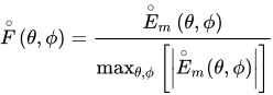 ,
,
where  — is the complex amplitude of the vector at a point in the far zone.
The radiation pattern is characterized by the width  of its main beam at the 0.5 level of its maximum power value and by the gain
  , which are related by:
 ,
,  ,
,  ,
,
where  ,
,  — are the effective area and extent of the antenna aperture.
Radiation patterns are usually described not only in a plane but also in a three-dimensional representation. To simplify their consideration, two projections of the radiation pattern are used:
horizontal (azimuthal)
vertical (in elevation)
When the projections are considered together, a more complete picture of the radiation pattern itself becomes clear and, as practice confirms, from these data one can judge the effectiveness of the antenna as applied to solving a specific problem.
There are amplitude  , phase Δω(θ, φ), and polarization
  ↑↓(θ, φ) radiation patterns.
By the shape of the radiation pattern, antennas are usually divided into narrow-beam and wide-beam types. Narrow-beam antennas have one pronounced maximum, called the main lobe, and secondary maxima (usually having a detrimental effect), whose amplitude they strive to reduce. Narrow-beam antennas are used to concentrate the power of radio emission in one direction in order to increase the range of radio equipment, as well as to improve the accuracy of angular measurements in radar. Wide-beam antennas have, in at least one plane, a radiation pattern that they strive to make close to circular. They find application, for example, in television and radio broadcasting. The lobes of the radiation pattern are often called the beams of the antenna.
The radiation pattern of an antenna is determined by the amplitude-phase distribution of the electromagnetic field components in the antenna aperture — a certain conventional computational plane associated with its design. The design of an antenna with a required radiation pattern thus reduces to the problem of ensuring the necessary electromagnetic field pattern in the plane of the aperture. There are fundamental limitations that relate, in inverse proportion, the beam width and the relative size of the antenna, that is, the size divided by the wavelength. Therefore, narrow beams require large antennas or the use of shorter waves. On the other hand, maximum narrowing of the beam for a given antenna size leads to an increase in the level of the side lobes. Therefore, at this point one has to make an acceptable compromise.
Radiation patterns are usually measured in the horizontal or vertical planes, and for feeds — in the E or H planes.
The radiation pattern of an antenna has the property of reciprocity, that is, it has similar characteristics for transmission and reception in the same wavelength range.
The study of the radiation pattern of small antennas is carried out in anechoic chambers. For large antennas that do not fit in the chamber, scaled-down models are used; the wavelength of the radiation is also reduced by the corresponding factor.
When constructing the radiation pattern for radio telescopes, a bright point source in the sky is chosen (often — the Sun). Then a series of observations is carried out at different angles, allowing the intensity distribution as a function of direction to be constructed, that is, the sought radiation pattern.
Formation of the radiation pattern in antennas can be carried out by analog or digital methods.
The digital method is used in digital antenna arrays. Digital beamforming involves the digital synthesis of the radiation pattern in the reception mode, as well as the formation of a specified distribution of the electromagnetic field in the aperture of the antenna array in the transmission mode .
The most widespread implementation of digital beamforming (English digital beamforming) is based on the fast Fourier transform operation , which makes it possible to form an orthogonal system of so-called secondary spatial channels, in which the maximum of the radiation pattern of one channel coincides with the nulls of the others.
Directional antennas are often used, whose main property is the ability to concentrate the radiated energy in a narrow sector. The width of this sector is determined by the points at which the radiated power decreases by half compared with the power radiated in the direction of the main maximum. The space bounded by the rays emanating from the electrical center of the antenna and passing through these points is called the antenna beam . Within the antenna beam, about 80 percent of all radiated power is emitted. As a rule, the antenna beam has the shape of a conical cutout from a sphere, more often highly directional (needle beam, pencil-type beam), but sometimes wider in one of the planes (fan-shaped beam).
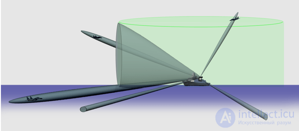
Figure 1. Beams of a shipborne radar antenna (example)
In the case of a continuous-wave radar, this geometric shape is completely filled with radiated power. When very short probing pulses are used, however, the radiated power fills not the entire volume of the antenna beam but only a small part of it, called the resolution volume. In this case, the antenna beam of the radar can be represented as a conduit directing the movement of the radiated pulse.
Graphically, the antenna beam of a radar corresponds to the image of the main lobe of the antenna's radiation pattern. As an example, Figure 1 shows different types of main lobes of the radiation pattern of a shipborne radar system's antenna: pencil-type (needle) and fan.
According to the standard definition, «the beam area is the solid angle through which all the power radiated by the antenna would be radiated if P (θ, Ø) retained its maximum value over Ω A and were equal to zero elsewhere».
The radiated beam of an antenna leaves at an angle to the antenna, known as the solid angle, where the radiation power intensity is maximal. This solid angle of the beam is called the beam area . It is denoted by Ω A.
The radiation intensity P (θ, Ø) must be maintained constant and maximal throughout the solid beam angle Ω A , while its value elsewhere is equal to zero.
Power radiated=P( theta, Phi) OmegaA watts
The beam angle is the set of angles between the half-power points of the main lobe.
The mathematical expression for the beam area is
OmegaA= int2 pi0 int pi0P pi( theta, Phi)d Omega watts d Omega= sin theta d theta d Phi watts
where
The unit of beam area is W .
According to the standard definition, « beam efficiency defines the ratio of the beam area of the main beam to the total radiated beam area».
The energy radiated by an antenna is projected according to the antenna's directivity. The direction in which the antenna radiates more energy has maximum efficiency, while part of the energy is lost in the side lobes. The maximum energy radiated by the beam with minimum losses can be called the beam efficiency .
The mathematical expression for beam efficiency is —
etaB= frac OmegaMB OmegaA
Where,
An antenna can be polarized according to our requirements. It can be linearly polarized or circularly polarized. The type of antenna polarization determines the shape of the beam and the polarization on reception or transmission.
When a wave is transmitted or received, it can be done in different directions. Linear polarization of the antenna helps maintain the wave in a specific direction, avoiding all other directions. Although this linear polarization is used, the electric field vector remains in a single plane. Therefore, we use this linear polarization to improve the directivity of the antenna.
When a wave is circularly polarized, the electric field vector turns out to be rotated, with all its components losing their orientation. The direction of rotation can also be different. However, thanks to the use of circular polarization, the effect of multipath propagation is reduced and, therefore, it is used in satellite communications such as GPS .
Horizontal polarization makes the wave weak, since reflections from the earth's surface affect it. They are usually weak at low frequencies below 1 GHz. Horizontal polarization is used in the transmission of television signals to achieve a better signal-to-noise ratio.
Low-frequency vertically polarized waves are advantageous for the transmission of ground waves. They are not affected by surface reflections, unlike horizontally polarized ones. Therefore, vertical polarization is used for mobile communications .
Each type of polarization has its advantages and disadvantages. The designer of a radio-frequency system can choose the type of polarization according to the system's requirements.
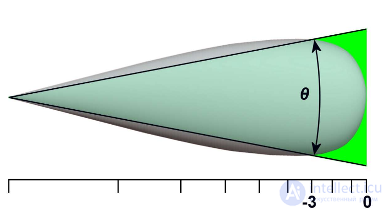
Figure 1. Illustrating the definition of the antenna beam width
The term «beam width» is usually understood to mean the width of the antenna beam at the half-power level. The direction of the antenna's maximum radiation is determined during a series of measurements (as a rule, in an anechoic chamber), after which, on both sides of it, the points are determined at which the radiation power decreases by half. The angular distance between the points corresponding to half power is the antenna beam width. The reduction of power to the half level can also be expressed in logarithmic units: -3 dB. Therefore, the antenna beam width at the half-power level is sometimes called the beam width at the -3 dB level (θ3) or (in English-language sources) HPBW (Half Power Beam Width). The antenna beam width is usually considered in the horizontal and vertical planes.
For the purpose of performing direct measurements of antenna parameters from signal oscillograms, measurement of the beam width by voltage is also used, at the points corresponding to a halving of the voltage, that is, at −6 dB. In such cases the notation θ6 is used. These points on the antenna radiation pattern have the same position as the half-power-level points. Considering that the impedance value does not change, halving the voltage will cause the current to halve. Multiplying the voltage and current, whose values are each halved, gives the result — a reduction of power by a factor of four, which on a logarithmic scale equals −6 dB. If, however, it is necessary to estimate the antenna beam width at the half-power level by measuring voltage, then the points are chosen at which the voltage level is 0.707 of the maximum.
In radio engineering, very strongly focused electromagnetic waves are called a pencil beam (literally «pencil beam») . This clearly describes a transmission beam that is «as thin as a pencil».
Antennas with a bundle of radio beams therefore have a very small beamwidth and, consequently, a very large antenna gain . Pencil antennas are used, for example, as fire-control radars . Genuine three-dimensional radars used in air defense also radiate bundles of radio waves .
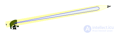
Graphical representation of a pencil radio beam.
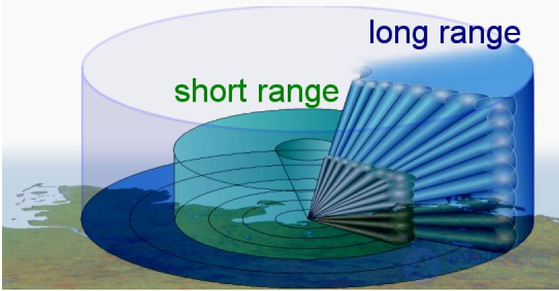
Radar with a three-dimensional pencil beam
In a first approximation, it is assumed that the side lobes can be neglected and that all the power generated by the transmitter is concentrated in the main lobe. In theoretical calculations, a correction to this approximation is used in the form of a beam-shape factor.
The second approximation consists in the assumption that the total power is radiated within the half-power beam width and is uniformly distributed within these limits (Figure 1, the area shaded green). On the other hand, it is assumed that no radiation occurs beyond the half-power beam width. To correct the error of applying such an approximation, a beam-width factor is introduced.
Based on these approximations, in the radar equation it becomes possible to use such parameters as antenna gain and transmitter power directly.
Lobes of the radiation pattern of a parabolic reflector
Ideally, the beam directed by the antenna at the feed should have the shape of a sharp pencil. Unfortunately, since the wavelength in this case is small compared with the aperture (diameter) of the antenna, the fixed focal point is in reality not exact. This causes a slight divergence of the main beam and some undesirable pickup of off-axis signals. The resulting polar diagram consists of a narrow beam, called the main lobe, and a series of side lobes of smaller amplitude.
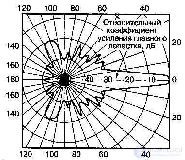
Fig. Typical radiation pattern of a parabolic reflector in polar coordinates
Since the polar diagram is often difficult to interpret, the representation in rectangular coordinates is preferred. The normalized theoretical signal characteristic for a uniformly illuminated antenna with a diameter of 65 cm at a frequency of 11 GHz is shown in the figure:
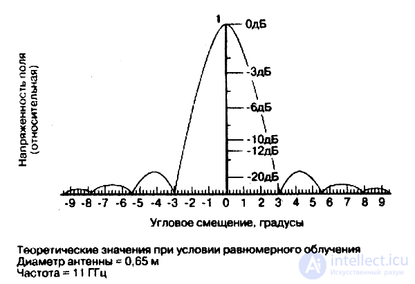
Lobes of the radiation pattern of a parabolic reflector
In reality, the factors listed above will contribute to introducing irregularities into this characteristic, but the overall picture of the dependence shown will remain unchanged.
Background noise enters the antenna system mainly through the side lobes, so it is necessary for them to be as small as possible relative to the amplitude of the main lobe. A uniformly illuminated antenna theoretically produces the first and largest of these side lobes at a level of about -17.6 dB below the maximum value of the main lobe.
In practice, the illumination is rarely uniform. The accuracy of the illumination distribution depends on the type of feed installed. This brings us to the concept of the effective area, or efficiency, of the antenna system. In other words, the greatest part of the signal power is collected from the central part of the dish and decreases toward the outer edges of the antenna. Therefore, a weak illumination of the antenna reflector aperture can serve as protection against background noise.
There are many antennas, often named after the geometric shape of the antenna pattern:

Comments