
Lecture
FERRITE ANTENNA — a magnetic antenna with a ferrite core. The high magnetic susceptibility of ferrites makes it possible to manufacture ferrite antennas with dimensions substantially smaller than those of a loop antenna, for the same electromotive forces induced in them.
If, for effective reception of radio waves, the antenna dimensions must be comparable to the wavelength, then how is it possible to receive long waves on the order of a kilometer in length using a compact ferrite antenna only about 10 cm long with a wound coil?
A small ferrite antenna receives long waves not by matching the wavelength, but thanks to magnetic induction and resonant amplification. It is not as efficient, but with powerful transmitters and a sensitive receiver this is sufficient.
1. The problem of scale
The wavelength of the long-wave band (LW, 150–300 kHz) can be 1–2 kilometers.
A classical antenna (for example, a dipole) must have dimensions comparable to the wavelength (on the order of λ/2), which is practically impossible for household devices.
2. How a ferrite antenna works
A ferrite rod with a wound coil is a magnetic antenna:
It responds not to the electric component of the wave (like a dipole), but to the magnetic component.
The ferrite concentrates the magnetic flux, enhancing the induction in the coil.
The coil converts the alternating magnetic field into an electric signal.
Thus, even a small coil can "sense" long waves, because it works as an inductive sensor rather than as a resonator a kilometer long.
3. The resonant circuit
To increase efficiency:
The coil together with a capacitor forms an LC circuit tuned to the frequency of the received station.
This circuit amplifies the signal through resonance, compensating for the small size of the antenna.
As a result, even a weak induced EMF becomes large enough for reception.
4. Limitations
A small antenna cannot collect as much energy as a full-size (kilometer-long) one.
Therefore the sensitivity of the receiver and the quality of the ferrite are critically important.
In household radio receivers, long-wave signals are usually powerful (radio stations radiate hundreds of kilowatts), which compensates for the low efficiency of the antenna.
5. Comparison
| Antenna type | Size | Principle | Efficiency |
|---|---|---|---|
| Dipole (λ/2) | ~1 km | Electric component | High |
| Ferrite coil | 10 cm | Magnetic component + resonance | Low, but sufficient with powerful transmitters |
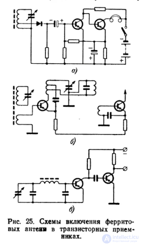
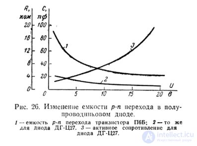
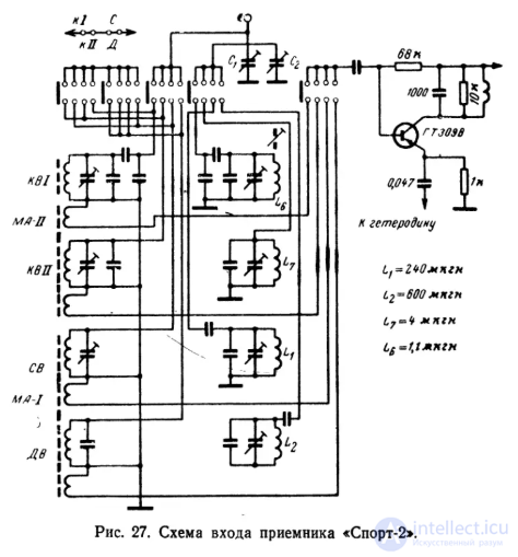
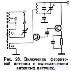
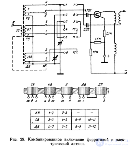
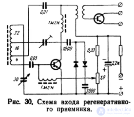
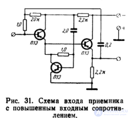
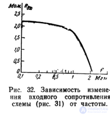
The main type of ferrite antenna at present is the antenna coil (loop) with a ferrite core described above. This type of antenna developed mainly along the lines of improving the winding types and selecting optimal core shapes and materials.
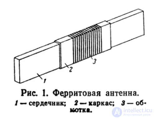
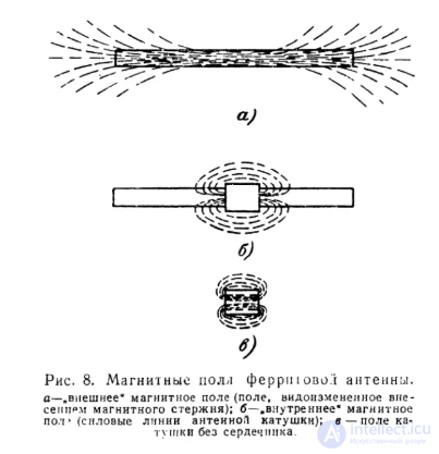
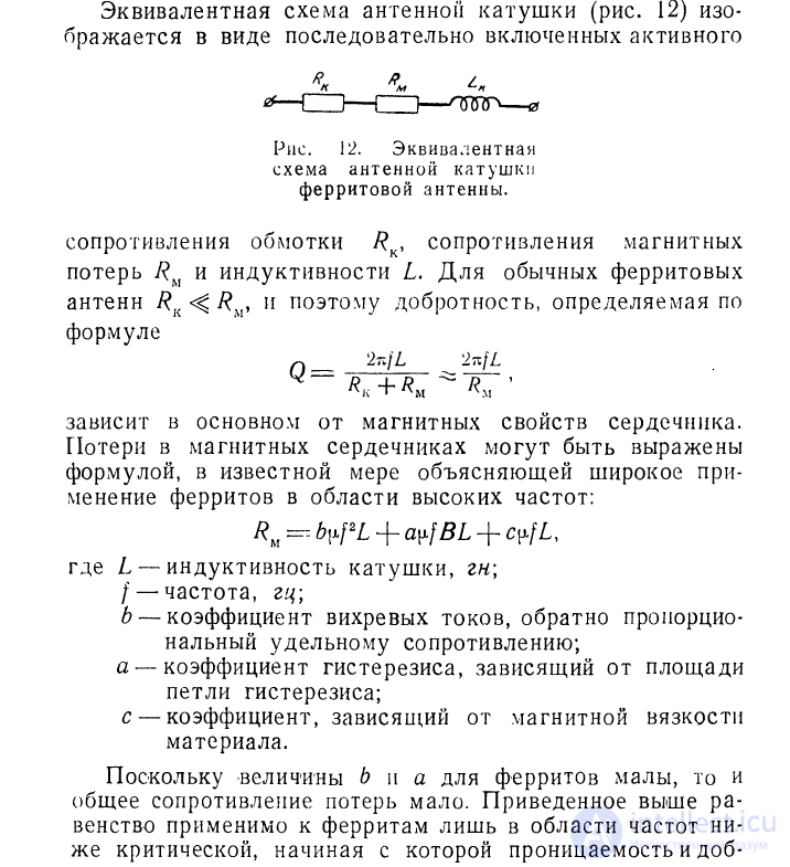
A comparative calculation of a receiving ferrite antenna shows that, when the input elements are correctly designed, it is usually comparable in efficiency to a whip of 1—2 m. In a number of cases such efficiency turns out to be insufficient, as a result of which the need arises to increase the effective height of the ferrite antenna. The practice of designing ferrite antennas has accumulated sufficient experience in the area of increasing efficiency. All these methods lead to some complication of the design.
The simplest way to increase efficiency is to enlarge the geometric dimensions of the core. The gain here is due to the fact that the inductance of the antenna coil grows with an increase in the core diameter in proportion to the first power of that increase, while the effective height is proportional to the square of the diameter. The drawback of this method lies in the increase in the size and weight of the core, since an increase in diameter must be accompanied by an increase in length so that the effective permeability of the core remains unchanged. In other words, increasing the diameter leads to a sharp increase in the volume and, consequently, the weight of the core (the specific gravity of ferrite is about 5 g/cm3).

Sometimes there is difficulty in choosing a core of an appropriate diameter. A way out of this difficulty may be found in using a set of cylindrical rods bundled together for this purpose. In this case the useful cross-sectional area of such a core, which determines the effective height, increases by a factor of Z^0.42, where Z is the number of rods in the bundle, while the inductance increases by a factor of Z^0.38, if the l/d ratio is sufficiently large. Fig. 16 shows the design of an antenna core made from a bundle of cylindrical rods.
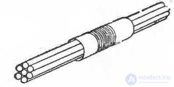
Fig. 16. Antenna with a core made of a bundle of rods.
Another method of increasing the effective height of a ferrite receiving antenna consists in connecting several ferrite antennas in series or in parallel. The idea of connecting several antennas in series is close to the idea of sectioning the antenna coil. Indeed, by dividing the antenna coil into two parts, placing these parts on two rods and connecting them in series, we reduce the antenna inductance by almost a factor of 2, since the coupling between the antennas is already negligibly small at a distance of 2—3 cm from each other. This makes it possible to increase the total number of turns in both coils by approximately a factor of √2 with continuous winding. If such a division of the antenna coil is performed on three rods, the number of turns can be increased by approximately a factor of √3, on four — by approximately a factor of 2, and so on. It should be noted, however, that an increase in the number of rods is accompanied by an increase in the coupling between them, and therefore the inductance of an antenna coil wound on n rods decreases by less than a factor of n, since the inductance of each of the parts will be equal to:

where K1, K2, Kn-1 — mutual-inductance coefficients.
When individual antennas are connected in series, the rods must be parallel, and the individual antenna coils must not be connected in opposition to one another, which is achieved by identical winding of the coils and appropriate connection of the ends of the windings (Fig. 17,a).
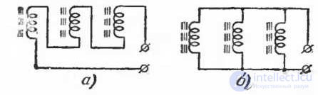
Fig. 17. Connection schemes for antenna coils
a — series connection; b — parallel connection.
Parallel connection of individual antenna coils (Fig. 17,b) leads to equally positive results. In the absence of, or with weak, coupling between two antenna coils connected in parallel, the inductance of such an antenna decreases by half, which can likewise be compensated by increasing the number of turns by a factor of √2. Similarly, as with series connection, with a large number of rods the possibility arises of a greater increase in the number of turns and, consequently, an increase in the efficiency of the antenna. An obstacle to increasing the number of rods here, besides the factors mentioned above, should be considered the rapid increase in the self-capacitance of the ferrite antenna. Fig. 18 shows a photograph of VHF-band ferrite antennas with parallel connection of the antenna coils.
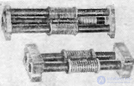
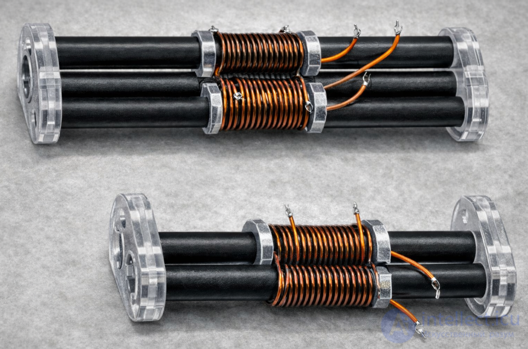
Fig. 18. External appearance of ferrite ultra-short-wave antennas.
Some gain in efficiency can be achieved by using cores with a variable (along the length) cross-section. In this case the thickened parts of the core are used as concentrators of the external field. As an example, let us consider a ferrite antenna whose core has a variable cross-section of the form shown in Fig. 19,a. Measurements carried out with ferrites having low magnetic permeability show that if, at a distance of one third from the ends of the core, its diameter is doubled while the diameter of the middle part is left unchanged, then the effective height of the antenna increases by a factor of 2.5—3, while the inductance of the antenna coil increases by only 20—30%. The stated size ratios of the shaped core are given merely as an example and probably do not fully characterize the maximum gain that can be obtained by the proposed method.
Another way of increasing the magnetic flux is the use of a core consisting of parts possessing different magnetic properties (Fig. 19,b). In particular, to concentrate the magnetic flux of the external field, the larger part of the core is made of a material with increased magnetic permeability, while the part of the core carrying the antenna coil, whose material determines the Q-factor of the antenna, may be made of ferrite with lower permeability but also with lower losses.
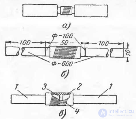
Fig. 19. Ferrite antennas with non-uniform cores.
a — with variable cross-section; b — with variable permeability; c — with a non-magnetic gap
(1 — core, 2 — former, 3 — spacer, 4 — winding).
A certain modification of this method may be the introduction of a non-magnetic gap into the core. In this design (Fig. 19,c) the antenna core consists of two halves fastened together by means of a spacer (washer) made of polystyrene (glued to the core with epoxy resin). The introduction of such a spacer increases the Q-factor of the antenna coil by a factor of 1.5 while increasing the number of its turns by 20%. The thickness of the spacer is taken to be on the order of 1—1.5 mm.
Of course, combinations of both methods are also possible: cores with a shaped profile can be assembled from various parts consisting of magnetic materials differing in properties. Their joining should be preceded by careful grinding of the mating surfaces. It should be taken into account that a loose fit of the ferrite surfaces reduces its magnetic permeability.
Allowance for this reduction can be made by the formula
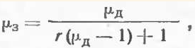
where μe — effective permeability of the core with a gap;
r — the ratio of the length of the air layer to the total length of the core.
To improve the radiation pattern, ferrite antennas employ an electrostatic screen made of a well-conducting material and following the shape of the antenna core. In doing so, the conducting surface of the screen must not form current loops whose direction coincides with the current in the antenna coil. For this, for example, in a cylindrical screen a slit is cut along its entire length. Practice shows that the screen should be located at a sufficient distance from the antenna coil (no closer than 1 cm). Thin silver-plated brass or bronze foil is usually used as the material for the screen. In some designs, fabric (nylon or other) with the finest metal threads woven into it is used for the screen. The use of metal coatings is also possible.
In the ferrite antenna designs we have considered, the classical scheme of their connection was assumed. It was considered that the antenna coil is part of a tuned antenna circuit. The natural choice in this case was a core material with low magnetic losses. However, in some cases it appears expedient to use ferrites whose cutoff frequency is below the operating range of the antenna. Such antennas may be called aperiodic, since in this case the loss resistance usually exceeds the inductive reactance of the antenna coil. One such antenna is described below (p. 53).
Ferrite antennas are also used in the microwave (SHF) band. They are based on the principle of the dielectric antenna (the use of ferrite as a medium for the propagation of radio waves). Owing to the relatively high dielectric permittivity of ferrite (10—14 in the microwave band), such an antenna, having the form of a long truncated cone, is capable of providing a single-lobe radiation pattern no more than 25° wide with a gain of about 40 in the 3-centimeter wavelength band.
A schematic drawing of such an antenna is presented in Fig. 20. The antenna consists of a ferrite rod about 11 cm long, with a maximum diameter of no less than 6 cm and a minimum diameter of 0.38 cm, a modulating coil, a short section of circular waveguide for exciting the rod, a filter, and a short section of ordinary rectangular waveguide.
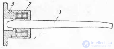
Fig. 20. Microwave ferrite antenna.
1 — ferrite rod; 2 — modulator; 3 — waveguide flange.
The radiating rod is made of low-loss ferrite with tgδ=0.0013 and dielectric permittivity ε=13.6. The ferrite-filled section of circular waveguide has an internal diameter of 6.25 and a length of about 19 mm. The filter is a copper strip conductor (0.5 thick and 1.5 mm wide) passing through the ferrite. The wave excited in the rectangular waveguide then passes into the section of circular waveguide filled with ferrite. The presence of the ferrite rod forces the wave excited in the circular waveguide to propagate further along the rod, as if along a waveguide of variable cross-section. However, unlike a waveguide, where the metal walls completely screen the internal field, the wave propagating along the ferrite rod is only partially reflected from the boundary with the air, while otherwise, at all points of the surface, it emerges outward. As a result of this, the radiation pattern of the ferrite microwave antenna turns out to be considerably sharper than, for example, the radiation pattern of an open waveguide end. It depends on the cross-sectional area of the ferrite body along its entire length, the dielectric and magnetic permeability, the length of the rod, and so on.
The described ferrite antenna, besides its main purpose (radiation of electromagnetic energy), is also used as a modulator. The role of the latter is played by the coil, which is fed with a current of about 10 mA. As a result of the Faraday effect, the longitudinal magnetic field caused by the solenoid rotates the plane of polarization of the wave in such a way that the losses in the filter increase sharply, weakening the signal level by more than a factor of 100.
The simplicity of such an antenna, its small dimensions, and also the possibility of control make it possible to design multi-row arrays with a large gain and an electrically controllable radiation pattern.
New designs of ferrite antennas are also being developed. Thus, one foreign journal described a ferrite short-wave antenna used as a transmitting antenna. Its structure is shown in Fig. 21.
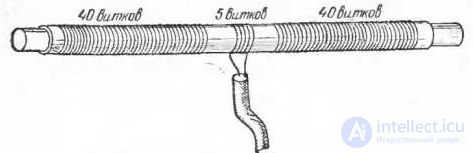
Fig. 21. Spiral ferrite transmitting antenna.
The core used here is a thick (5 cm in diameter) ferrite bar about 1 m long. From an electrical point of view, such an antenna represents a horizontal dipole (radiator) with a very large artificial «shortening» (the shortening factor of such an antenna, depending on the grade of ferrite and the winding method, can reach 100 and more), which varies with frequency. As a result, in the short-wave band (1—10 MHz) this antenna has several sharp resonances, representing a «harmonic» wire.
The input impedance of this antenna changes sharply with frequency from a few units to several thousand ohms. Such an antenna does not lend itself to tuning and as yet has no practical significance. However, what is noteworthy in this design is the use of ferrite as a medium that changes the parameters of the current carrier — its inductance and capacitance.
Close in idea to the one described is the so-called «spiral antenna», tested by the author in the 150—300 MHz band. The antenna is a spiral with a small (3—5) number of turns, wound on a cylindrical ferrite core 25 mm in diameter and 250 mm long with permeability μo = 15. It was mounted on a metal sheet, to which the braid of the feeding coaxial cable was soldered; the cable core was connected to the spiral at its upper end. The input impedance of the antenna was close to 150 ohms over the entire band. However, its efficiency turned out to be very low (no more than 10%), which is explained primarily by the magnetic losses that increase with frequency.
More successful was the use of ferrites as a compensation element in an ordinary electric antenna — a dipole. Here the placement of the ferrite elements along the length of the dipole, as well as the grade of ferrite, prove to be significant. The design of such an antenna, intended for television, is described in more detail in the last chapter.
In principle, other types of ferrite antennas are also possible. Let us consider some of the most promising of them.
Of great interest is the use of ferrites in slot antennas. A cylindrical slot antenna, whose external appearance is shown in Fig. 22, is very close to a loop antenna both in the distribution of current on its surface and in its polarization properties.
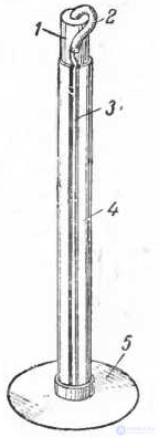
Fig. 22. Cylindrical slot antenna.
1 — ferrite core; 2 — feeding cable; 3 — slot; 4 — conducting cylinder; 5 — base.
Its surface represents a single turn, with the turn diameter (for an air slot antenna) being approximately one third, and the height of the antenna — somewhat more than half the wavelength. The effective height of the slot antenna is equal to the length of the slot, and the input impedance depends on the point of cable connection and varies from 600 to 150 ohms. This antenna possesses resonant properties, with the resonance frequency being determined by the length of the slot, on condition that the cylinder diameter must be sufficient to avoid shunting by the turn with its small inductance. With the help of ferrite, the diameter of a cylindrical slot antenna can be reduced by approximately a factor equal to the square root of the effective magnetic permeability of the core.
No less promising is an antenna based on the use of the Hall effect. As already mentioned, a ferrite core can be used as a concentrator of the magnetic field acting on the sensor. In this case it is advisable to place the sensors in a small gap between two rods — concentrators, then the magnetic flux in the gap is Φ_g = kΦ, where k may be on the order of 0.25. Calculations show that at present the «voltage» sensitivity of the sensors is insufficient for designing effective antennas; however, in the future such antennas appear quite realistic.
Inductance adjustment
In the design calculation of a ferrite antenna, one should take into account the possibility of adjusting the inductance of the antenna coil after it is installed in the receiver. Most often this is done by moving the antenna coil along the rod, which makes it possible to change the inductance by 20%. Another method of adjustment is carried out by changing the gap between the two halves of the core (Fig. 39,a).
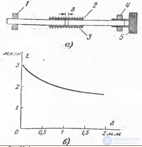
Fig. 39. Antenna with an adjustable air gap.
a — construction of the antenna (1 — holder, 2 — former, 3 — winding,
4 — holder with a threaded hole, 5 — flange with a running thread);
b — graph of the inductance variation as the gap changes.
Fig. 39,b shows the dependence of the inductance of the antenna coil on the size of the gap δ between the halves of a core made of 20VCh ferrite. By using ferrites with higher magnetic permeability, a greater frequency coverage can be achieved. There is one more method of adjusting the antenna inductance, consisting in changing the distance between the sections of the antenna coil (Fig. 40). Owing to its very large range of inductance variation, such adjustment can be used as the main method of tuning the ferrite antenna, making it possible to dispense with a variable capacitor.
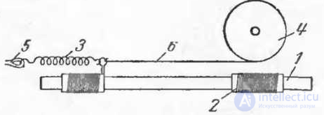
Fig. 40. Inductance adjustment by changing the distance between the sections.
1 — core; 2 — coil section; 3 — spring; 4 — pulley; 5 — attachment point; 6 — cord.
To reduce the length of the connecting wires, the ferrite antenna should be installed as close as possible to the input stage. There must be no short-circuited turns in the vicinity of the antenna. The antenna should be fastened in holders with soft pads. To avoid an increase in self-capacitance, the antenna must be kept away from the chassis at a distance of no less than 3 cm, and also kept as far as possible from transformers and the electrodynamic loudspeaker.
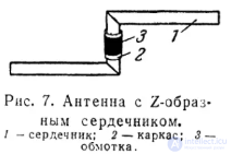
Sometimes it becomes necessary to fabricate «bent» cores, among which, for example, is the Z-shaped core (Fig. 7). Such a core, in directional reception, makes it possible to change the position of the antenna without changing the position of the coil.
A core of such a configuration can be obtained by gluing its separate parts (horizontal and vertical) with BF adhesive or epoxy resin. The contacting surfaces of the core must be ground and glued in accordance with the generally accepted technology used with one or another adhesive.
When gluing, it is necessary to monitor the temperature at which the core is dried so that it does not rise to the Curie point for the given ferrite.
The efficiency of a ferrite antenna is determined by the properties of the core (the material and dimensions of the core) and by the characteristics of the magnetic pickup (its design). It also depends on the frequency of the
signal — other things being equal, the efficiency of a ferrite antenna increases with frequency. It should be noted that the efficiency of a ferrite antenna can increase by almost a factor of two due to the
presence of a conducting surface nearby, in contrast to electric antennas, where the close location of a surface reduces the antenna's efficiency.
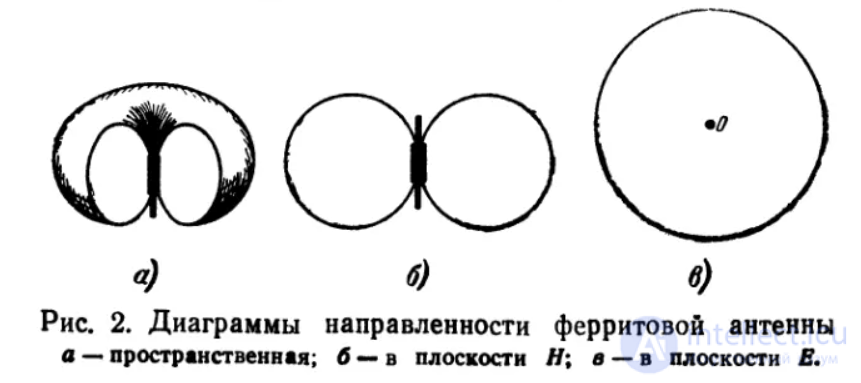
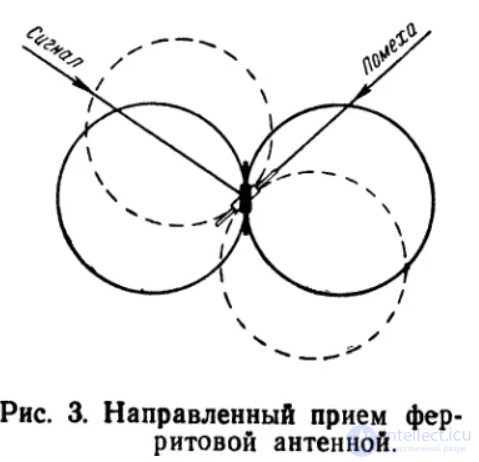
In a number of cases, the possibility of obtaining a directional antenna becomes the main, decisive factor necessitating the use of a ferrite antenna. Precise determination of the direction of arrival of radio waves, knowledge of the transmitter's azimuth, is very important in navigation — maritime and aerial, during air flights under conditions of poor visibility, and so on. The era of space flight, opened up by the Soviet Earth satellites, further increases interest in radio navigation. Millions of people all over the world observed the movement of the satellites visually with admiration. The use of radio-observation means with precise determination of the direction of arrival of the radio waves emitted by the satellites expands the possibilities of scientific observations and can provide valuable information about the trajectory of the satellites' motion, about the features of radio-wave propagation, and so on.
Described below is the simplest ferrite antenna for determining the direction of arrival of radio waves (the azimuth) at a frequency of 40 MHz. In such an antenna it is necessary to take special measures preventing distortion of the radiation pattern, as well as the influence of the operator himself (owing to the antenna effect) on the results of the radio observation. By the antenna effect is usually meant the absence of full symmetry of the antenna, which manifests itself in the form of errors in determining the azimuth, as well as in the form of an indistinct null of the pattern, which likewise worsens the results of radio observations. The azimuth of the radio transmitter is determined by setting the antenna in such a position where the signal strength is minimal. This position of the antenna relative to the directions of the magnetic meridian is marked on a special angular scale in degrees.
The electrical circuit of the antenna is shown in Fig. 1. The antenna circuit (three antenna coils wound on three parallel rods, and a capacitor) is connected to the input of a push-pull cathode follower. A balancing transformer is included in its cathode circuit, providing the transition from the balanced circuit to the unbalanced cable. In this stage, a 6N3P double triode or two 1Zh17B tubes can be used. The cable is connected to the unbalanced input of an ordinary receiver. Resistances (of the ULI type) of a few ohms are included in the grid circuits of the triodes to prevent self-oscillation.
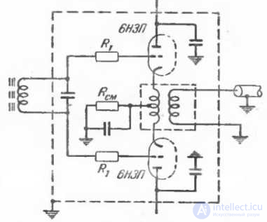
Fig. 1. Circuit of a ferrite antenna for determining the direction of arrival of radio waves in the ultra-short-wave band.
To eliminate the antenna effect, the antenna circuit together with the input tubes and the transformer is enclosed in a metal screen (tin, brass) with a slit passing through the entire screen parallel to the antenna rods. When assembling the device, one should provide maximum high-frequency bypassing of the filament and anode supply circuits. The rotating device of the antenna must provide rotation through an angle of up to 200°. Stops must be installed in it to protect the cable from twisting.
The choice of rods for the antenna should be approached from the standpoint of obtaining its maximum efficiency. Good results are given by an antenna assembled on rods 25 mm in diameter with a permeability of 20. The length of the cores is 250 mm (they are assembled from four columns 60—65 mm long each). The number of turns of the antenna coils is 12 with a winding pitch of 10 mm.
A drawback of the described circuit lies in the need for additional retuning. After searching for the desired radio station on a non-directional antenna, in order to determine the direction one should switch from the non-directional to the ferrite antenna and then retune it.
The direction can also be determined with the help of an untuned antenna. In this case the antenna coil is coupled by means of a short cable to the input circuit, which is tuned to the radio station. Besides a rotatable magnetic antenna, a stationary antenna system of ferrite antennas is sometimes made, using a goniometer in this case. The antenna system in this case consists of two mutually perpendicular antennas (or two groups of antennas connected in parallel). The leads of each antenna coil are connected to the fixed coils of the goniometer, while the «search» coil, which acts as a kind of rotatable antenna, is included in the input circuit.
A short-wave goniometric direction finder with ferrite antennas described in the foreign press had two groups of eight ferrite antennas each. The antenna cores, about 30 cm long and 1.5 cm in diameter, were arranged in two «tiers» (the cores of one group above the cores of the other). The dimensions of such a system when assembled were 350x350x40 mm.

Comments