
Lecture
Lens antennas are aperture antennas of the optical type. As the name itself suggests, the principal element in these antennas is the lens, which converts a beam of rays diverging from the focus, where the radiation source is located (in transmit mode), into a beam of parallel rays at the lens aperture. Conversely, a beam of parallel rays incident on the lens aperture converges at its focus (in receive mode), where it is captured by a horn, an open waveguide end, a dipole, and so on.
The model representation of lens systems is carried out mainly in the coherent approximation. Nevertheless, in both the coherent and incoherent approximations the theoretical aspects of describing optical and radio-engineering lenses are analogous, since they are built on the basis of models of electromagnetic radiation propagation.
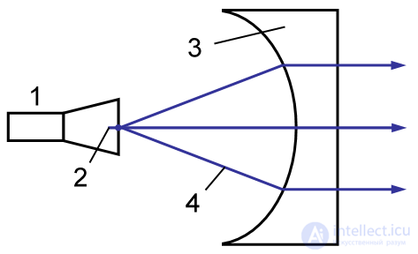
In lens antennas (hereinafter, lenses), feeds are used in the same way as in reflector antennas. For a lens antenna, the radiation pattern beamwidth and the directivity (directive gain coefficient) are calculated based on the aperture dimensions in wavelength fractions. The positions of the focal planes are determined in the same way as in geometric optics. In all cases, the model representation of radio-engineering lenses is analogous to the modeling of optical lenses. The model representation of phased antenna arrays is constructed in a similar manner. Lens antennas are divided into decelerating and accelerating types.
In decelerating lenses the phase velocity is less than the speed of light (analogous to optical glass lenses). Decelerating lenses are made of a high-frequency dielectric or of a lighter artificial dielectric with lower losses, which is a system of small metal disks, spheres, etc., mounted on a dielectric frame or embedded in expanded polystyrene or another dielectric with low losses and low permittivity.
In accelerating lenses the phase velocity is greater than the speed of light (as in a waveguide). Accelerating lenses are manufactured in the form of a system of parallel metal plates (metal-plate lenses) or sections of rectangular waveguides whose axes are parallel to the antenna axis. An example of an accelerating lens is shown in Fig. 1.
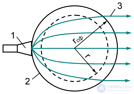
The advantage of lens antennas over reflector antennas (classic radar antennas) is that in them the feed does not shadow the aperture and does not distort the aperture distribution. There are several types of lens antennas that make it possible to provide a wide beam-steering (scanning) sector. This property is possessed, for example, by the spherical and cylindrical Luneburg lenses. In a Luneburg lens with spherical symmetry the refractive index must vary along the path of the rays. Gradient lenses (gradans) in optics are made in a similar way.
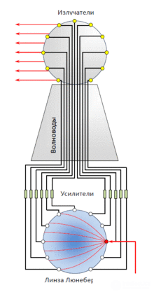
A radiation source (feed) located at the periphery of the lens (Fig. 2) creates a beam of parallel rays at its aperture. Moving the feed over the sphere causes the lens radiation pattern to swing in any direction. Usually a spherical Luneburg lens is excited by an array of feeds, and then each of the feeds corresponds to its own fixed, highly directional radiation pattern. The entire system of feeds together with the lens forms a multibeam antenna system capable of simultaneously serving a wide sector of angles, providing continuous radar surveillance of space within it, as well as conducting directional radio communication simultaneously with various correspondents located in different directions.
The Luneburg lens — a lens in which the refractive index is not constant but varies according to a certain law depending on the distance from the center in spherical lenses or from the axis in cylindrical lenses. Usually the law of variation of the refractive index is chosen in such a way that, on passing through the lens, parallel rays are focused at a single point on the lens surface, while rays emitted by a point source on the surface form a parallel beam.
This lens design was first proposed by the German/American mathematician Rudolf Luneburg.
A Luneburg lens partially covered with a conductive material has an enormous (relative to its true dimensions) radar cross section over wide angles of illumination. The maximum achievable RCS of a spherical Luneburg lens is defined as
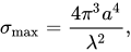
where  — is the radius of the lens, and
  — is the wavelength .
Luneburg lenses are widely used in microwave engineering. One such use is the creation of objects that strongly reflect radio waves. In particular, Luneburg lenses are used in target missiles to simulate the radar cross section of real targets with larger dimensions (for example, combat aircraft) .
The use of such lenses in optical technology is hindered by the technical difficulties of manufacturing lenses with a variable refractive index, which determines their high cost. Sometimes, to simplify the production technology, such lenses are assembled from discrete elements — small cubes with different refractive indices.
The Luneburg lens long remained no more than a mathematical curiosity, until in the early 1960s it was used as a beamformer in the American AN/SPG-59 radar.
The AN/SPG-59 radar was one of the first phased-array-antenna (PAA) radars in the world. Unlike modern phased-array radars, where the spatial beam pattern is formed by means of controllable phase shifters, the AN/SPG-59 radar used a Luneburg lens located in the ship's superstructure. The choice of this technology was dictated by the absence in the 1960s of compact and reliable C-band phase shifters.
Several thousand receiving and transmitting elements were located on the surface of the lens. When one of the transmitting elements formed a spherical radio wave on the lens surface, the lens converted it into a wave with plane-parallel fronts, whose phase pattern was picked up by the receiving elements and transmitted to a spherical radiator located at the top of the bell-shaped superstructure. In this way, the spherical radiator formed a beam in space whose direction corresponded to the position on the lens of the radiating element.
The reflected wave was received by three spherical receivers located around the perimeter of the superstructure and spaced 120° apart in azimuth. The signals from the several thousand receivers of the three antennas were combined and fed to the Luneburg lens, which focused the signal onto one of the receiving elements, whose position on the lens surface corresponded to the position of the target in space.
A test version of the radar was tested aboard the experimental ship AVM-1 «Norton Sound» from June 1964 to July 1966. The tests revealed low equipment reliability, high power losses in the lens, and poor quality of conversion of the spherical wave into a plane one (a high level of radiation-pattern side lobes). Subsequently, development of the radar was discontinued in connection with the winding-down of work on the «Typhon» project.
Among multibeam lens antennas, in addition to the Luneburg lens, one should include the Rotman lens and the R-2R lens. The operating principle of the Rotman lens is based on the fact that the lens, in its simplest implementation, consists of a region between parallel plates, fed by coaxial probes from two opposite sides. The probes on the right side of the lens (radiating-element inputs) are connected by a high-frequency cable of a specific length to the individual radiating elements of the antenna array at the lens aperture. The probes located on the left side of the lens (beam inputs) are distributed along the focal arc in such a way that each of them corresponds to a specific beam direction in space.
Different focal lengths, as shown in Fig. 1a). If the size of the parallel-plate waveguide is made larger, the delay-line network becomes shorter. We use a new routing scheme consisting of a series of straight lines and circular arcs. This network is usually smaller than the conventional one and causes lower radiation losses due to the larger radius of the arcs (compare Fig. 1b).
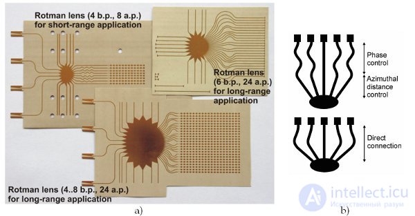
a) Examples of Rotman lenses for various automotive radar applications; b) Principles of constructing a network with delay lines.
Thanks to wireless communication, a great deal of energy is released into the air, and scientists had to try very hard to gather this energy in one place. Today there are developments that make it possible to convert short-range Wi-Fi signals into energy. Researchers are also experimenting with radio waves — they created a "trap" into which radio waves generated by a smartphone fall, then convert them into energy and power the battery of that same smartphone. In this way the device's battery works 30% longer.
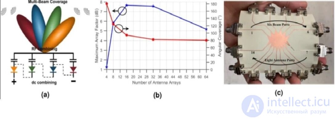
According to the researchers, harvesting millimeter-wave energy has been possible for some time, but in many cases it was impractical, because energy harvesting over large distances generally requires large rectifying antennas (rectennas), and the larger the rectennas become, the narrower their field of operation. As a result, you have to keep the rectenna pointed directly at the wave energy source for it to work correctly.
The solution to the problem — the Rotman lens. The team solved this problem with the help of a component called a Rotman lens — a pointed plate at the center of the rectenna (see photo). Rotman lenses are used as a tool that forms beams and turns a single, large, narrow-angle antenna beam with high gain into a series of antenna beams covering a much wider angle. For example, such lenses enable radar systems to see targets in several directions without the need to rotate or move the radar itself.
By adding a Rotman lens to the rectenna, the team obtained a flexible energy-harvesting system that is independent of direction, receives energy from any direction, and is capable of accumulating 21 times more energy than any analogs existing today.
The team says that the rectenna is capable of harvesting about 6 microwatts while at a distance of about 180 m from a 5G transmitter. This will be more than enough to power a number of small sensors and devices, especially where the Internet of Things is concerned. Devices connected to one another will be able to power themselves simply by harvesting energy that would otherwise be wasted. And the fact that the new rectenna design is suitable for printing on a 3D printer, is flexible, and works well even in a bent state means that it can also be used in wearable devices.

Comments