
Lecture
The high saturation of the modern aircraft with radio equipment‚ the large number of aircraft antennas installed over a comparatively small area, and the increased aircraft speeds require particular attention to the questions of designing and locating these antennas.
Aircraft antennas are of great importance for ensuring communication and navigation during flight. The designs and placement of these antennas are carefully developed to provide optimal performance. Here are the main features of the design and placement of aircraft antennas:
Types of antennas: Aircraft use various types of antennas depending on their purposes. For example, antennas for communication with air traffic control, antennas for receiving GPS/GLONASS/BeiDou/Galileo signals, antennas for air-to-ground communication, and others. Radars on the aircraft are important systems used to detect and track objects in the air environment. Each type of antenna has its own design and location.
Placement on the fuselage: Some antennas may be installed on the aircraft fuselage. This location provides good access to signals with minimal interference from the aircraft structures.
Built-in antennas: In some cases, antennas may be integrated into the aircraft structure, which allows aerodynamic drag to be reduced and the overall effective form factor to be improved.
High-gain antennas: To provide longer-range communication or reception of weak signals, high-gain amplified antennas may be used.
Antenna systems: Some aircraft may have several antenna systems, including antennas for airborne communication, antennas for GPS navigation, radio, and others. It is important that these systems be spaced apart across the aircraft to avoid mutual interference.
Antennas in critical zones: Antennas such as radio communication antennas and flight control systems are usually placed in critical zones of the aircraft to ensure reliable communication and navigation.
Electromagnetic compatibility: It is important to ensure that the antennas and their placement do not create electromagnetic interference for other systems aboard the aircraft.
Stability and strength: Antennas must be stable and robust in order to withstand aerodynamic loads, vibrations, and external effects.
Cable infrastructure: It is also important to take into account the cable infrastructure that connects the antennas to the receivers and transmitters aboard the aircraft.
Testing and certification: Before antenna systems are implemented, they undergo testing and certification to ensure their reliability and compliance with safety standards.
The operating conditions of aircraft antennas differ from those of ground-based ones. The requirements imposed on aircraft antennas follow from the specific — operating conditions and are subdivided into — mechanical, thermal, and radio-engineering requirements. Antennas should, where possible, be non-protruding or slightly protruding, occupy a minimal area on the skin and volume inside the aircraft, not disrupt its load-bearing structure, possess resistance to vibration and icing, retain functionality under conditions of flight at high altitudes, elevated humidity, and high and low temperatures, and not pick up radio interference arising from electrification. The design and placement of antennas must ensure minimal electromagnetic coupling between them; with a protruding design, high mechanical strength and low aerodynamic drag are required. The radio-engineering parameters of aircraft antennas must satisfy the requirements imposed by the specifics of the radio equipment.
The electromagnetic field is created by currents flowing in the antenna itself and along the aircraft body, i.e., the aircraft body participates in radiation on par with the antenna. As a result, the radiation pattern, input impedance, and other parameters of an aircraft antenna can differ greatly from the parameters of the same antenna located in free space. The aircraft's influence on the radio-engineering parameters depends on the type of antenna and its installation location on the aircraft, on the size and shape of the aircraft, and on the operating wavelength. The aircraft body most strongly affects weakly directional antennas, which is associated with their irradiating a significant part of the body. If, however, the antenna has a narrow radiation pattern and the main radiation is directed into a zone free from aircraft structural elements, then the influence of the aircraft body on its parameters will be insignificant. This section considers external weakly directional antennas (Fig. 12), whose operation is most specific under aircraft conditions. These include rigid wire, whip, and symmetrical (dipole) radiators. Rigid antennas are used for communication in their wavelength range and are stretched between a feed-through insulator and the aircraft fin. By their parameters they can be classified as long-wave antennas. Whip antennas are made in the meter and decimeter wavelength range and are asymmetrical radiators about a quarter of a wavelength in size (Fig. 12, b).
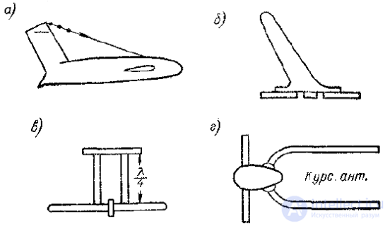
Fig. 12. Types of antennas used on aircraft:
A large cross section improves the bandwidth. A reduction in aerodynamic drag is achieved by flattening the antenna from the sides.
Symmetrical radiators are made with a large cross section.
Examples of these can be the antennas of the radio altimeter and of the localizer and glide-slope beacon receivers. All non-protruding weakly directional antennas can be divided into the following types:
— located in special recesses or niches made in the aircraft body;
— surface antennas in the form of copper or brass plates glued onto the cockpit glazing or onto special dielectric coatings;
— slot antennas cut into the aircraft skin;
— those exciting the aircraft body;
— surface-wave antennas.
An example of an antenna located in a niche‚ is the loop antenna of the ARK radio compass (Fig. 13, a).
Surface antennas (Fig. 13, b, c) can be applied onto the cockpit glazing or onto a special dielectric substrate. Slot antennas are cut into the aircraft skin or form a self-contained structure with excitation and a cavity (Fig. 13, d). A groove antenna (Fig. 13, e) is an asymmetrical slot cut into the edge of the aircraft's empennage.
Usually the size of the groove is close to a quarter of a wavelength. For non-directional radiation, ring-shaped and U-shaped slots are used.
Any weakly directional antenna excites currents in the aircraft body; however, this does not mean that the body then radiates efficiently. The efficiency of
radiation turns out to be low, since the currents of the aircraft body compensate for one another. The methods of intense excitation of the aircraft body can be
divided into two kinds: series and parallel. In series excitation, the aircraft body is cut at some location and an EMF is inserted. The most acceptable method is the insulation of the top of the fin or the end of one of the wings (Fig. 13, f). Such antennas can be regarded as an asymmetrically excited linear radiator.
An antenna of parallel excitation of the aircraft body is the shunt antenna (Fig. 13, g). It is less efficient than a series-excitation antenna,
and its efficiency is also not high. An example of a surface-zone antenna is a dielectric one, cut along the axis and placed on the aircraft skin
(see Fig. 13, h).
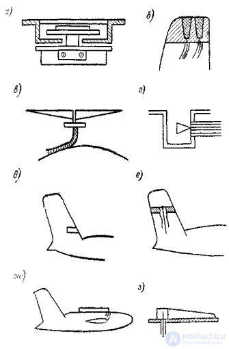
Fig. 13. Weakly directional aircraft antennas: a — loop; b — surface; d - e — slot; f — series excitation of individual parts of the aircraft — the fin; g — parallel excitation of the aircraft body (shunt antenna); h — dielectric antenna.
The development and placement of aircraft antennas is an important task that requires engineering expertise in order to ensure reliable communication and navigation during flight.

Comments