
Lecture
The Friis transmission formula — one of the equations of Harald Friis (Harald Friis), used in telecommunications. It determines the power received by one antenna under ideal conditions from another antenna located at a certain distance and transmitting a known power. The Friis transmission formula is used in telecommunications engineering, equating the power at the terminals of the receiving antenna to the product of the power density of the incident wave and the effective aperture of the receiving antenna under idealized conditions, where the other antenna at some distance transmits a known amount of power. The formula was first presented by the Danish-American radio engineer Harald T. Friis in 1946. This formula is sometimes called the Friis transmission equation.
Friis's original idea behind his transmission formula was to abandon the use of directivity or gain when describing antenna characteristics. Their place is taken by the descriptor of the antenna's capture area as one of the two important parts of the transmission formula, which characterizes the behavior of the free-space radio channel.
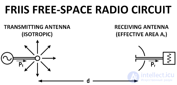
Friis's free-space radio circuit.
This leads to the transmission formula he published:
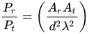
where:
 – the power supplied to the input terminals of the transmitting antenna;
  — the power available at the output terminals of the receiving antenna;
  – the effective aperture area of the receiving antenna;
  – the effective aperture area of the transmitting antenna;
  – the distance between the antennas;
  – the wavelength of the radio frequency; and are in the same units of power; , ,
  , and
, and  are in the same units. is large enough to ensure a planar wavefront at the receiving antenna, sufficiently approximated by the formula
  where
where  — the largest linear dimension of either antenna.
Friis stated that the advantage of this formula over other formulations is the absence of numerical coefficients that need to be memorized, but it requires expressing the characteristics of the transmitting antenna in terms of power flux per unit area instead of field strength, and expressing the characteristics of the receiving antenna in terms of its effective area rather than by power gain or radiation resistance.
Few follow Friis's advice on using the antenna's effective area to characterize antenna performance, compared with the modern use of directivity and gain measures. Replacing the effective areas of the antennas with their gain counterparts yields
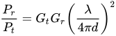
where  and
and  — the antenna gains (relative to an isotropic radiator) of the transmitting and receiving antennas respectively,is the wavelength, representing the effective aperture area of the receiving antenna, andis the distance between the antennas. If the equation is used as written, the antenna gains are dimensionless values, and the units of wavelength () and distance () must be the same.
For a calculation in decibels, the equation takes the form:

where:
 — the power supplied to the terminals of the isotropic transmitting antenna, expressed in dB.
  - the power available at the terminals of the receiving antenna, equal to the product of the power density of the incident wave and the effective aperture area of the receiving antenna, proportional to , in dB.
  — the gain of the transmitting antenna in the direction of the receiving antenna, dB.
  — the gain of the receiving antenna in the direction of the transmitting antenna, dB.
 The simple form applies under the following conditions:
 , so that each antenna is in the far field of the other.
 Ideal conditions are almost never achieved in ordinary terrestrial communication due to obstacles, reflections from buildings, and, most importantly, reflections from the ground. One situation where the equation is accurate enough is satellite communication, where atmospheric absorption is negligible; another situation is found in anechoic chambers, specially designed to minimize reflections.
Given for ideal conditions (no obstacles, reflections, multiple possible transmission paths, etc.). The antennas are assumed to be co-directional in polarization.
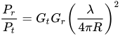 , where :
— The gain of the transmitting antenna — The gain of the receiving antenna — the power of the transmitting antenna (W) (excluding losses) — the power received by the antenna (W) (excluding losses) — the distance between the antennas in meters — the wavelength in meters, corresponding to the transmission frequency
In space telecommunications, when the radiation is directed into space, the formula must be adjusted for atmospheric attenuation and diffraction from random obstacles. Thus, the simple form of the equation should be regarded as the «best-case scenario». The link will fail if the received signal power drops below the level required for correct demodulation (called the sensitivity threshold).
In its simplest form, the Friis transmission equation is as follows. Given two antennas, the ratio of the power available at the input of the receiving antenna, , to the output power of the signal-transmitting antenna,, is given as
2
where and are the antenna gains (relative to an isotropic radiator), transmitting and receiving respectively, is the wavelength, and is the distance between the antennas. The reciprocal third factor is the so-called free-space attenuation. To use the equation as written, the antenna gains must not be given in decibels, and the units of wavelength and distance must be the same. If the gain is given in dB, the equation changes to the following form:
 (The gain is given in dB, and the power has units of dBm or dBW)
Besides the usual derivation of the formula from antenna theory, the basic equation can also be obtained from the principles of radiometry and scalar diffraction, and in this way it emphasizes an understanding of the physical content.
The simple form applies only under the following ideal conditions:
 (meaning that is much greater than ). If
  , then the equation would give a physically impossible result in which the received power is much greater than the source power, which would be a violation of the law of conservation of energy.is understood as the power at the terminals of the antenna receiving the signal. There are transmission losses through the cable from the antenna to the connection. In addition, the power at the antenna output will be fully transferred to the transmission line only when the antenna and the transmission line are perfectly matched (see impedance matching).is understood as the power delivered to the transmitting antenna. There are losses occurring through the cable running from the antenna to the connectors. In addition, the power at the antenna input is fully transferred into free space only when the antenna and the transmission line are perfectly conjugate matched (conjugate matched).
Ideal conditions are almost never attainable in ordinary communications on the Earth's surface, due to obstacles, reflection of the signal from buildings, and, most importantly, reflection from the ground surface. One case where the equation is accurate enough is satellite communication, where atmospheric absorption can be considered negligible; a second case is the anechoic chamber, specially built to minimize signal reflections.
The effects of impedance mismatch, imperfect matching of antenna orientation and polarization, and absorption can be added by including additional factors; for example:

where
 the gain of the transmitting antenna in the direction
 in which it "sees" the receiving antenna.
 the gain of the receiving antenna in the direction
 in which it "sees" the transmitting antenna.
 andΓ
andΓ are the reflection coefficients of the transmitting and receiving antennas, respectively
 and
and are the polarization vectors of the transmitting and receiving antennas, respectively, taken in the corresponding directions.
 is the absorption coefficient of the intervening medium.
Empirical calculations are also sometimes made on the basis of the basic Friis equation. For example, in urban conditions there are strong multipath propagation effects, and under such conditions it is not clear whether a direct line-of-sight exists; the formula in the following 'general' form can be used to determine the 'averaged' ratio of input and output signal powers:
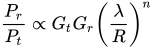
where  is determined experimentally, and usually lies in the range from 3 to 5, and and are taken as the average effective gains of the antennas. However, to obtain a useful result for further refinement, it is usually necessary to apply more complex equations, such as the Hata model for urban areas.
There are several methods for deriving the Friis transmission equation. In addition to the usual derivation from antenna theory, the basic equation can also be obtained from the principles of radiometry and scalar diffraction in a way that emphasizes physical understanding. Another derivation is to take the limit of the near-field transmission integral.

Comments