Lecture
Topic 10 . Methods of coding physical signals in computer networks .
Lecture 16 .
16 1 Physical coding .
Note that in this lecture we will look at the coding of signals and not information. The purpose of coding is to encode or transform the "0" and "1" of the incoming code into the levels of electrical signals in the communication lines.
The progress of recent years in the field of increasing the capacity of digital channels is associated with the development of digital data transmission technology. Here we need to solve the problems of synchronization, efficient coding and reliable transmission.
The synchronization problem is that when generating a signal, the duration of the elementary position of the signal and the cycle of their arrival on the transmitting side are strictly specified and determined by the clock frequency of the transmission system. At the receiving end, for correct restoration of the signal, it is necessary to have exactly the same clock frequency parameters and, moreover, synchronization to a separate clock frequency is required.
To solve the synchronization problem, there are two data transfer methods: synchronous and asynchronous . Asynchronous method is used for relatively low-speed transmission channels and autonomous equipment. The synchronous method is used in high-speed channels and is based on sending a synchronizing clock signal through a separate channel or by combining it with the transmitted data . With synchronization of the receiver and the transmitter, it is possible to transmit longer sequences of zeros or ones, without failures at their reception.
A typical data frame in an asynchronous channel starts with a start bit, followed by 8 data bits. Such a frame ends with one or two stop bits. The start bit has a polarity opposite to the passive state of the line and puts the receiver into the active state. An example of the transfer of such a frame is shown in Fig. 16.1
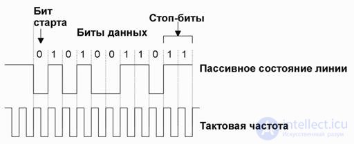
Fig. 16.1 Example of frame transmission in asynchronous mode
The initial and stop bits for each data byte reduce the bandwidth of the channel and for this reason are used only for low exchange rates. Increasing the length of the data block leads to stricter requirements for synchronization accuracy. When using the synchronous transmission method, special measures are necessary to separate synchronization from the general data stream. To solve this problem, special properties of the transmitted code are usually used, from which the clock pulses are extracted.
Consider the various methods of coding signals for transmitting signals over an optical, conduit line. .
We mainly consider coding methods for computer networks — or as they are called Ethernet — 10Base-T and 100 Base-TX and 1GB Ethernet standards.
16 2 Self-synchronizing codes - codes RZ and Manchester - II.
Rz code
RZ is a three-level code that provides a return to zero level after the transmission of each bit of information. It is called so - "coding with return to zero" (Return to Zero). A logical zero corresponds to a positive impulse, a logical one to negative.
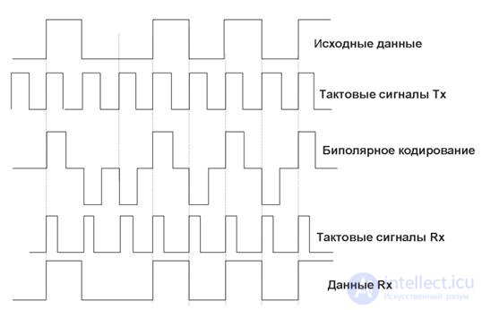
Fig. 16.2. Example of bipolar signal coding (RZ circuit - return-to-zero)
Information transition is carried out at the beginning of a bit, return to zero level - in the middle of a bit. A feature of the RZ code is that there is always a transition (positive or negative) in the center of a bit. Therefore, every bit is indicated. The receiver can separate the clock (strobe), which has a pulse repetition rate, from the signal itself. Binding is made to each bit, which ensures synchronization of the receiver with the transmitter. Such codes that carry a strobe are called self-synchronizing.
The disadvantage of the RZ code is that it does not give a gain in data transfer speed. Transmission at 10 Mbps requires a carrier frequency of 10 MHz. In addition, to distinguish between the three levels (+1, 0, -1), a better signal-to-noise ratio at the input to the receiver is needed than for two-level codes.
Most often the RZ code is used in fiber optic networks. When transmitting light, there are no positive and negative signals; therefore, three power levels of light pulses are used. (P = "1", 0.5P = "0", 0P = "- 1")
Code Manchester II
The Manchester-II code or the Manchester code is most prevalent in local area networks. It also applies to self-synchronizing codes, but, unlike the RZ code, it has not three, but only two levels, which provides the best noise immunity.
With a low exchange rate (10 Mbps) is used Manchester code, in which the logical unit is encoded by the transition of a signal from a low level to a high (Fig. 2 and Fig. 11.3 ), and a logical zero - a transition from a high level to a low. The disadvantage of the Manchester code is the wide band of the frequency spectrum associated with the need to switch signal levels when each binary digit arrives.
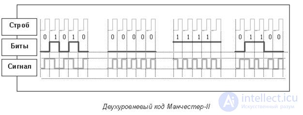
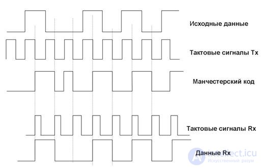
Fig. 16.3. Signal coding using Manchester code.
The great advantage of the Manchester code is the absence of a constant component when transmitting a long sequence of ones or zeros. Due to this, galvanic isolation of signals is performed in the simplest ways, for example, using pulse transformers.
The Manchester II code has found application in copper and fiber-optic data transfer networks. The most common Ethernet protocol 10 Mbps uses this particular code.
16 3 Non-self-synchronizing codes . - NRZ code .
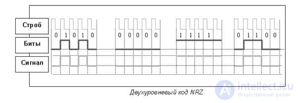
Code NRZ (Non Return to Zero) - without returning to zero - this is the simplest two-level code. Zero corresponds to the lower level, the unit - the upper. Information transitions occur on the border of bits.
The undoubted advantage of the code is simplicity. The signal does not need to be encoded and decoded.
In addition, the data transfer rate is twice the clock frequency. The highest frequency will be recorded when alternating ones and zeros. At 1 Hz, two bits are transmitted. For other combinations, the frequency will be less. When transmitting a sequence of identical bits, the frequency of change of the signal is zero.
Code NRZI - Non Return to Zero Invert to ones non-return to zero method with inverting for units. This method is a modification (NRZ). The NRZI method also uses two signal potential levels, but the potential used to encode the current bit depends on the potential that was used to encode the previous bit (the so-called differential coding). If the current bit is 1, then the current potential is the inverse of the value of the previous bit , regardless of its value. If the current bit is 0, the current potential repeats the previous one.
NRZ and NRZI code is not synchronized. This is its biggest drawback. If the receiver clock frequency is different from the transmitter frequency, synchronization is lost, bits are distorted, data is lost.
 |
Fig. 16.4. Codes NRZ, NRZI and MLT3
To synchronize the start of receiving a packet, the start service bit is used, for example, one.
The most well-known application of the NRZI code is the USB protocol — into USB 2.0, the transfer rate is up to 480 Mbps. In addition, it is used in very broadband data transfer channels — the ATM155 standard has a transfer rate of 155 MB.
The most common RS232 protocol used for connections over a PC serial port also uses the NRZ code. Information is transmitted in bytes of 8 bits, followed by start and stop bits.
16 4 High Speed Codes - MLT code - 3 and PAM 5.
The three-level transmission code MLT-3 (Multi Level Transmission - 3) has a lot in common with the NRZ code. The most important difference is the three signal levels.
The unit corresponds to the transition from one signal level to another. The change in the signal level occurs consistently with the previous transition. The maximum signal frequency corresponds to the transmission of a sequence of units. When transmitting zeros, the signal does not change. Information transitions are fixed on the border of bits. One cycle of the signal holds four bits.
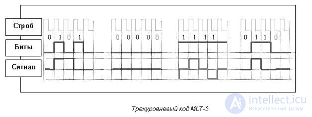
Figure 16.5. Three-level code MLT-3
The lack of MLT-3 code, as well as the NRZ code, is the lack of synchronization. This problem is solved with the help of data conversion, which eliminates long sequences of zeros in the code and eliminates the possibility of desynchronization.
Additional data conversion is performed using the 4B5B data pre-coding method.
Protocols that use the NRZ code are most often complemented by coding 4B5B data. Unlike signal coding, which uses a clock frequency and provides a transition from pulses to bits and vice versa, data coding converts one sequence of bits to another.
The 4B5B code uses a five-bit basis for transmitting four-bit information signals. The five-bit scheme gives 32 (two to the fifth power) two-digit alphanumeric characters having a decimal value from 00 to 31. Four bits or 16 (two to the fourth power) characters are given for the data.
The four-bit information signal is recoded into a five-bit signal in the transmitter encoder. The converted signal has 16 values for transmitting information and 16 redundant values. In the receiver decoder, the five bits are decoded as information and service signals. For service signals, nine characters are reserved, seven characters are excluded.
Combinations with more than three zeros (01 - 00001, 02 - 00010, 03 - 00011, 08 - 01000, 16 - 10000) are excluded. Such signals are interpreted by the symbol V and the command of the VIOLATION receiver — a failure. A command indicates an error due to a high level of interference or transmitter failure. The only combination of five zeros (00 - 00000) refers to the service signals, means the symbol Q and has the status QUIET - no signal in the line.
Data coding solves two problems - synchronization and noise immunity improvement. Synchronization occurs by eliminating a sequence of more than three zeros. High noise immunity is achieved by monitoring received data in a five-bit interval.
Price data coding - reducing the speed of transmission of useful information. As a result of adding one extra bit to four informational ones, the efficiency of using a frequency band in protocols with the MLT-3 code and data encoding of 4B5B decreases accordingly by 25%.
When MLT-3 signal coding is used together with 4V5B data, the transmission rate is 3 bits of information per 1 hertz of the signal carrier frequency. This scheme is used in the TP-PMD protocol.
Higher speed code PAM code 5
The signal coding schemes discussed above were bitwise. When bit-coding, each bit corresponds to the signal value determined by the logic of the protocol.
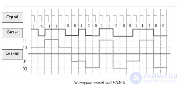
Figure 16.6. Five-level code RAM 5
When encoding a signal level, blocks of two bits are specified.
In the five-level code PAM 5 5 amplitude levels and two-bit coding are used. For each combination, set the voltage level. With two-bit coding, four levels are necessary for transmitting information (two to the second degree - 00, 01, 10, 11). Transmitting two bits simultaneously reduces the frequency of signal change by a factor of two.
The fifth level is added to create redundancy code used for error correction. This gives an additional margin of signal to noise ratio of 6 dB.
The PAM 5 code is used in the protocol. 1000 Base T Gigabit Ethernet . This protocol provides data transmission at a speed of 1000 Mbps with a width of the signal spectrum of only 125 MHz.
16 5 Required frequency band for data transmission and signal spectrum width .
Signal coding is a way to hang more than one bit of the transmitted information for one clock period. What is the purpose of conversion? In order to increase speed without changing the frequency range of the communication channel. Coding requires the use of more sophisticated transceiver equipment. This is a minus. But in the transition to faster protocols, you can use the same cables. And this is a big plus.
For example, the Fast Ethernet 100 Base T4 protocol provides network performance at a speed of 100 Mbit / s on Category 3 (16 MHz) cables when encoded by the NRZI method. Gigabit Ethernet 1000BaseT is implemented in such a way that, based on cable category 5 (100 MHz band), which has some reserve, it can transmit 1000 Mbps.
The spectral width of the signal depends on the clock frequency, coding method and filter characteristics of the transmitter.
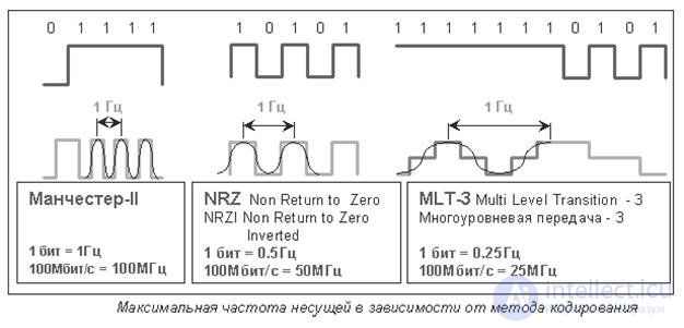
Fig.16.7 Maximum carrier frequency depending on the coding method.
Figure 16.7 illustrates how the coding method can reduce carrier frequency. For the three coding methods, situations are given that require a maximum carrier frequency. One carrier period transmits one bit (1) in Manchester coding, two bits (01) of the NRZ code and four bits (1111) of the MLT-3 code. The coding factor (transmission) is respectively one, two and four.
Other bit combinations require a lower frequency. For example, when alternating zeroes and ones, the frequency of the MLT-3 code spectrum decreases by another two times, a long sequence of zeroes reduces the carrier frequency to zero.
The spectral width of the signal should not be confused with the clock frequency.
The clock frequency is the metronome, which sets the tempo of the melody. In Figure 6, the clock frequency corresponds to the bit alternation of the input information sequence .. The spectral width of the signal in this analogy is the signal envelope provided that it allows the original pulse signal to be recovered.
16 6 Test questions .
1. What are the goals of signal coding at the physical level?
2. What is the difference between self-synchronizing and non-self-synchronizing codes?
3. Which of the codes is potentially more productive: two-level or multi-level?
4. What code is used for transfer in USB 2.0 interface?
Comments
To leave a comment
Information and Coding Theory
Terms: Information and Coding Theory