
Lecture
Sensor calibration. Counting intersections. Following an inverted line.
Many different approaches can be used for line following, but they all depend on the number of sensors mounted on the robot for the robot to observe the line. Let's talk about how the number of sensors affects the robot's ability to follow a line.
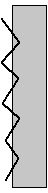
This method of line following requires only one sensor. In fact, the robot does not follow the line itself, but its edge, constantly switching between dark and light. The robot is also fitted with two drives: one motor turns on when the line is visible but turns off when the line is not visible, while the other is activated when the line is not visible but turns off when the line is visible. In this way, the robot, wobbling from side to side, moves along the boundary between black and white. This works great at slower speeds, but becomes unsuitable for use on a high-speed bot. If the sensor crosses the line, it may turn around and drive in the opposite direction; if the robot loses the line, it starts spinning continuously. Because of its simplicity, this type of sensor setup is rarely used in microcontroller-based bot designs. The sensor can be in one of two possible states, 1 or 0 (see figure)
Sensor operating conditions:
0 – line not visible
1 – line visible
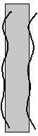
The operating principle is similar to the single-sensor scheme, but each sensor controls its own motor. The line lies between the sensors, and they, in turn, try to avoid it. At high speed this scheme works better than the previous one. But if the line is lost, the robot will start to wander. This happens because the bot cannot distinguish between the edge of the line and losing it entirely. This drawback can be fixed in software if a microcontroller is used as the robot's brain. The smaller the gap between the line and the sensor, the more precisely the robot will follow the line.
Sensor operating conditions:
00 - the line's boundary is lost
01 - line on the right
10 - line on the left
11 - Not used, if the distance between the sensors is greater than the width of the line.
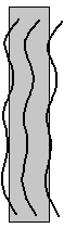
By adding a third sensor to the previous design, the bot can determine the line and its edges. This lets the robot notice when it is drifting off the line. This scheme also adapts more easily to changing conditions; you can increase speed on straight sections, or fine-tune the control more precisely.
This is one of the most common designs; the brain of a robot with this many sensors is usually a microcontroller.
Sensor operating conditions:
001 - line on the left
010 - line in the center
011 - line has drifted slightly left
100 - line on the right
101 - not used
110 - line has drifted slightly right
111 - Not used (but can be used to track the line in a maze or on complex tracks with intersections)
Three sensors are obviously enough to follow a line effectively, so why would we want to add two more? The answer to this question comes down to the main quality that matters for line-following robots – speed. Adding two more sensors increases sensitivity, and the sensors can detect the position of the line under the robot's bumper with greater resolution. When the bot is not moving too fast, there is plenty of time to adjust direction and speed to stay on the line. But what happens when the speed increases significantly? Instead of gracefully following the line, the bot starts oversteering and can fly off the track.
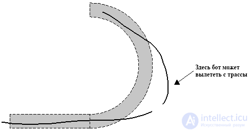
This can be fought in two different ways:
At some point, because of the speed, your robot will exceed its ability to control itself. Knowing this, you can program it to correct for the bot overshooting the line, so that it is able to find the line again.
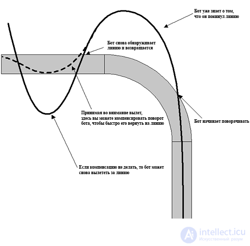
In the example in the photo above, the robot lost the line when it entered a turn. Since it started turning left when the line disappeared from under it, it knows it needs to turn left until it finds the line again, with its leftmost sensor (at a fairly sharp angle) before any other sensor. Under normal conditions, only the left sensor, seeing the line, will turn the robot all the way to the left. But only in order to bring it back to the line without merging into it. This returns the bot back onto the track, and keeps it from flying over the line. Unlike the previous scheme, here it is very important to have two more additional sensors. They serve for more precise control and faster reaction to overshoot and oversteering. Click here to watch a video of my robot Arty.
As in other projects, let's look at the possible operating conditions with five sensors (I have listed only the useful ones):
00000 - Loss of the line from excessive speed or a break in the line.
00001 – The robot has almost lost the line, it is necessary to turn fully to the right and reduce speed.
00011 – line at the right edge, turn to the right.
00010 – the line has drifted right, stay at the right edge.
00110 - slightly right of the center of the line, a small correction to the right.
00100 - centered on the line, increase speed for straight sections.
01100 - Slightly left of the center of the line, a small correction to the left.
01000 - The line has drifted left, stay at the left edge.
11000 - line at the left edge, turn left.
10000 - The robot has almost lost the line, it is necessary to turn fully to the left and reduce speed.
11111 - intersection of the line, or the circle at the end of the maze.
As you can see, if we use 5 sensors, we get much finer control over the bot’s movement. By looking at the sensor states as binary numbers, we can easily program our robot’s logic.
Below is a code snippet from Arty, my latest line-following robot. This is the main logic loop, which controls both the steering and the speed, and accounts for overshooting the line, while also trying to compensate for oversteering. It is written in BASCOM for the DevBoard-M8.
Lineflag is a variable that holds the binary representation of the state of the 5 sensors.
Servo (1) is the PWM channel for the steering servo.
Servo (2) is the PWM channel for the drive servo.
Overshoot is a flag indicating that the bot lost the line in a turn.
Bascom Main code segment for Arty:
|
1
2
3
4
5
6
7
8
9
10
11
12
13
14
15
16
17
18
19
20
21
22
23
24
25
26
27
28
29
30
31
32
33
34
35
36
37
38
39
40
41
42
43
44
45
46
47
48
49
50
51
52
53
54
55
56
57
58
59
60
61
62
63
64
65
66
67
68
69
70
71
|
Case &B00000 'No line 'If the bot loses the line, make steering changes Servo(2) = Slow - Progspeed If Lastlineflag < 4 Then Overshoot = 1 'Overshot a righthand corner Elseif Lastlineflag > 4 Then Overshoot = 1 'Overshot a left hand corner End IfCase &B00100 'Line under center sensor Overshoot = 0 Servo(1) = Center Servo(2) = Mediumfast - ProgspeedCase &B00110 Overshoot = 0 Servo(1) = Smallright Servo(2) = Mediumfast - ProgspeedCase &B00010 Overshoot = 0 'Line under midright sensor Servo(1) = Mediumright Servo(2) = Mediumfast - ProgspeedCase &B00011 'Line between midright and right sensor If Overshoot = 0 Then Servo(1) = Largeright Servo(2) = Medium - Progspeed Else Servo(1) = Mediumright Servo(2) = Medium - Progspeed End IfCase &B00001 'Line under right sensor If Overshoot = 0 Then Servo(1) = Hardright Servo(2) = Mediumslow - Progspeed Else Servo(1) = Largeright Servo(2) = Mediumslow - Progspeed End IfCase &B01100 'Line between center and midleft sensor Overshoot = 0 Servo(1) = Smallleft Servo(2) = Mediumfast - ProgspeedCase &B01000 'Line under midleft sensor Overshoot = 0 Servo(1) = Mediumleft Servo(2) = Mediumfast - ProgspeedCase &B11000 'Line between midleft and left sensor If Overshoot = 0 Then Servo(1) = Largeleft Servo(2) = Medium - Progspeed Else Servo(1) = Center Servo(2) = Medium - Progspeed End IfCase &B10000 'Line under left sensor If Overshoot = 0 Then Servo(1) = Hardleft Servo(2) = Mediumslow - Progspeed Else Servo(1) = Largeleft Servo(2) = Mediumslow - Progspeed End IfEnd Select |
So, we see that 5 sensors provide a finer degree of control, which allows the bot’s speed to be increased on straight sections to compensate for the time spent going through turns.
Conclusion
Which of the four schemes presented is right for your robot? That’s up to you. The simplest is the two-sensor scheme. More sensors will give you more control, but you will most likely need to use a microcontroller to process the data from all the sensors. Use the method that matches your needs and skill level - each design has its own advantages.
Addendum
Below is the complete program used by Arty 1.0, my first line-following robot, which has an articulated frame. It includes code for automatic calibration of the line sensors.
This program was written for the ATMega8 in Bascom-AVR. The Servo command is used to control the steering servo and control speed.
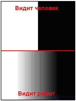
At first this may seem strange, but motion along the boundary between black and white can also be built using a P-controller. Although on the surface the task appears solvable only with a relay (bang-bang) controller, since the system has only two states visible to the human eye: black and white. But the robot sees things differently; for it, there is no sharp boundary between these colors.
You could say it is nearsighted and sees a gradient transition of shades of gray. This is exactly what will help us build a P-controller.
Just as with a relay controller, we need to determine the average value between black and white; let’s call it grey. This will be the state of the light sensor s1 that the system should aim for.
while(true)
    {
      up=k*(s1-grey);
      motor[MotorB]=50+up;
      motor[MotorC]=50-up;
      wait1msec(1);
    }
The coefficient  can be fairly small (from 1 to 3) for a maneuverable device.
Such a controller works effectively only for small deviation angles, so the device must be positioned in the direction of travel so that the sensor ends up on the left side of the black line. If the sensor drifts onto the black line, the controller becomes negative and the left motor will run slower than the right one, which straightens the robot out. It's easy to notice that line following with a P-controller is distinguished by its smoothness, and in some sections the robot moves nearly in a straight line, or precisely follows the curves of the line.

Comments