
Lecture
Feedback. Traveling around a room. Protection against getting stuck. Practical application of room-traversal movement — robot vacuum cleaners
In control problems there are usually two objects: the controlling one and the controlled one. In the simplest case, the controlling object issues a command and the controlled object executes it without reporting anything about the result or about changed operating conditions. This is the essence of feedforward control (fig. 8.1).
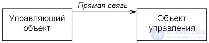
Fig. 8.1. Feedforward control.
From the point of view of a mobile robot, the controlling object is its controller running a program, and the controlled object is its wheels and body (chassis). The controller issues control commands to the motors, and under feedforward control it is guided by the readings of its own internal clock — a timer.
The first class of problems with which programming begins is controlling the robot's movements. Let's look at them in order. As programming environments we will use Robolab 2.9.4 for beginners and RobotC for more advanced programmers. As the robot model we will use any two-motor cart.
Motor control commands are used for forward movement. These commands simply turn the motors on. A feature of the NXT is that after the program finishes running, all the settings in the robot's behavior are kept, but the motors stop receiving power. Thus, the robot starts moving and then immediately coasts to a smooth stop (fig. 8.2).

Fig. 8.2. Turning the motors on.
Both commands execute almost instantly. If the motors are switched off right after them, the cart will simply jerk and remain standing in place (fig. 8.3):

Fig. 8.3. Stopping when trying to start moving.
Task main() { motor[motorB] = 100; motor[motorC] = 100; motor[motorB] = 0; // stop motor motor[motorC] = 0; }
Thus, some delay is required before switching off the motors in order to actually produce movement. Wait commands do not perform any specific actions themselves, but they give the motors a chance to do their part of the work (fig. 8.4):

Fig. 8.4. The correct order for controlling the motors.
Task main() { motor[motorB] = 100; motor[motorC] = 100; wait1Msec(1000); // Wait 1000 ms motor[motorB] = 0; motor[motorC] = 0; }
Forward or backward movement is, of course, determined by the direction the motors rotate (fig. 8.5). No stop is required to change direction:

Fig. 8.5. Drive forward for a second, backward for a second, and stop.
Task main() { motor[motorB] = 100; motor[motorC] = 100; wait1Msec(1000); motor[motorB] = -100; // "Full reverse" motor[motorC] = -100; wait1Msec(1000); motor[motorB] = 0; motor[motorC] = 0; }
At the moment of a direction change at high speed, skidding is possible. Smooth braking is possible. To do this, power is removed from the motors before issuing the "reverse" command, and the robot coasts for a while under its own inertia (fig. 8.6).

Fig. 8.6. Coast for half a second under inertia before changing direction.
A shorter interval than 1 second is set using the "N/100" command and a modifier. In Robolab 2.9.4 you can specify the time in milliseconds with the "N/1000" command:
Task main() { motor[motorB] = 100; motor[motorC] = 100; wait1Msec(1000); // Turn on floating mode for motor control bFloatDuringInactiveMotorPWM = true; motor[motorB] = 0; motor[motorC] = 0; wait1Msec(500); motor[motorB] = -100; motor[motorC] = -100; wait1Msec(1000); // Turn on "braking" mode bFloatDuringInactiveMotorPWM = false; motor[motorB] = 0; motor[motorC] = 0; }
In Robolab, ordinary commands turn the motors on in floating mode, while RobotC uses "braking" mode by default, which allows for more precise control. But Robolab also has "advanced" commands for controlling the motors in braking mode, with a power range of –100...100.
Turns
To turn in place, it is enough to turn the motors in opposite directions. The robot will then rotate approximately around the center of the drive-wheel axle, with some offset toward the center of gravity. For a more precise turn, the time needs to be tuned in hundredths of a second (fig. 8.7). However, whenever the battery charge changes, new turning parameters will have to be entered:
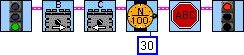
Fig. 8.7. Turning in place.
Task main() { motor[motorB] = 100; // Motors in opposite motor[motorC] = -100; // directions wait1Msec(300); motor[motorB] = 0; motor[motorC] = 0; }
There is another type of turn. If one motor is stopped while the other is left running, rotation will occur around the stationary motor. The turn comes out smoother this way (fig. 8.8):

Fig. 8.8. A smooth turn.
Task main() { motor[motorB] = 100; motor[motorC] = 0; wait1Msec(1000); // only motor B is rotating motor[motorB] = 0; }
Moving in a square
Using what we've learned about controlling the motors, we can program movement in a square or any other polygon using a loop or an unconditional jump (fig. 8.9):

Fig. 8.9. Moving along a polygon with smooth turns.
Task main()
{ while (true){ motor[motorB] = 100; motor[motorC] = 100; wait1Msec(1000); motor[motorC] = 0; wait1Msec(1000); motor[motorB] = 0;
}
}
By fine-tuning the turn duration and the number of repetitions, we can teach the cart to drive around the perimeter of a square once (fig. 8.10). For turning accuracy, we'll reduce the motor power by roughly half. You will have to work out the delays yourself:

Fig. 8.10. For a 90-degree turn, the duration will have to be worked out yourself.
Task main() { for(int i=0;i<4;i++){ // The loop runs 4 times motor[motorB] = 50; motor[motorC] = 50; wait1Msec(1000); motor[motorC] = -50; wait1Msec(400); motor[motorB] = 0; } }
The appearance of feedback in a system means that the controlling object starts receiving information about the controlled object
(fig. 8.11).
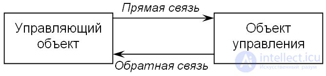
Fig. 8.11. Control with feedback.
Feedback is implemented using sensors attached, for example, to the robot's body. The data goes to the controller, which is the controlling object.
Precise movements
So that a turn doesn't depend on the battery charge, we can use the rotation sensor built into the motors, the "encoder", which allows measurements accurate to 1 degree. For more effective control, we'll use Robolab's "advanced" commands, assuming that when the cart turns 90 degrees, the left wheel turns 250 degrees around its own axis (fig. 8.12):
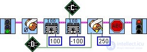
Fig. 8.12. Precise turn in place.
task main() { nMotorEncoder[motorB]=0; // Encoder initialization motor[motorB] = 100; motor[motorC] = -100; // Empty loop waiting for the encoder reading while(nMotorEncoder[motorB]<250); motor[motorB] = 0; motor[motorC] = 0; }
For the first experiment, the robot built for the "Dance in a Circle" task will work, using the same field — a black circle on a white background. If everything is already ready for making a full-fledged field for a track, you can refer to the "Field" section at the end of this part. The only correction: the light sensor should be moved forward a little so that, together with the drive wheels, it forms an equilateral, or at least an isosceles right, triangle (fig. 8.32).
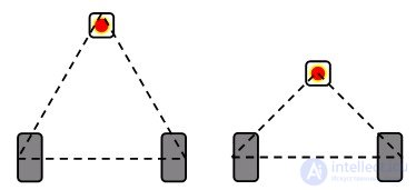
Fig. 8.32. Options for positioning the light sensor relative to the drive wheels.
The task is as follows: move along the circle, following the border between black and white. It is solved trivially by using a relay (or proportional) controller, which is discussed in the "Control Algorithms" chapter. The only difference is that the algorithm will be written not as branching, but using the "Wait Darker" and "Wait Lighter" blocks. The basic design is shown in figs. 8.33–8.35, and the simplest program for beginners in fig. 8.36. Without modifiers, it is assumed that the light sensor is connected to the first port, and the motors are supplied with maximum power.
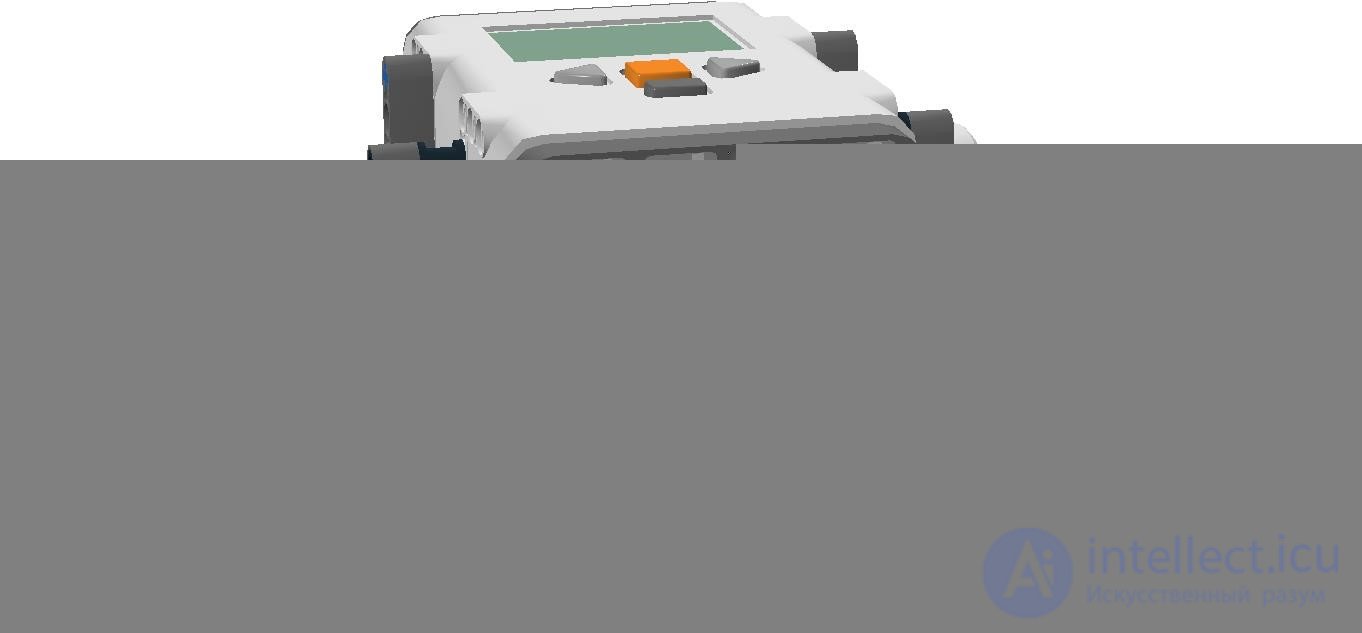
Fig. 8.33. Mounting the light sensor on a three-wheeled cart.
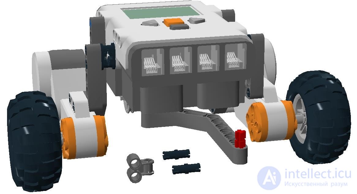
Fig. 8.34. The rod for adjusting the sensor height can be any length.
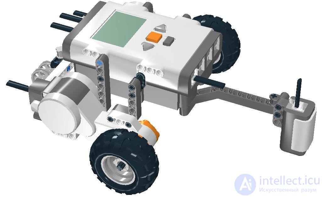
Fig. 8.35. The sensor height above the field surface — from 5 to 10 mm.

Fig. 8.36. Algorithm for line following with a single light sensor.
Before the start, place the robot on the line so that the sensor is slightly to the left. According to the algorithm, the robot smoothly turns right until the light level drops by 5 points (by default). Then it turns left until the light level rises by 5 points. The resulting movement looks like a "zigzag".
Possible problems
Let's list the difficulties that may arise:
— the robot spins in place without getting onto the line. In this case, either start from the other side of the line, or swap the motor connections to the controller;
— the robot overshoots the line without having time to react. The motor power should be reduced;
— the robot reacts to small disturbances on white without reaching black. The sensor's sensitivity threshold needs to be increased (for example, not 5 but 8 points). Generally speaking, this number can be calculated. To do this, take the sensor reading on white, then on black, subtract one from the other, and divide by two. For example, (56 – 40) / 2 = 8.
The improved program is shown in fig. 8.37.

Fig. 8.37. Line-following algorithm with a single light sensor: reduced speed, increased difference between black and white.
The algorithm works more reliably if motors with speed control of –100...100 are used. In this case, it is possible to adjust the smoothness of the turn to match the curvature of the line
(fig. 8.38).
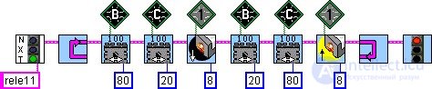
Fig. 8.38. Line-following algorithm with a single light sensor: improved motor control.
In this algorithm, the braking motor on a turn does not stop completely, but only reduces its speed to 20 points. This makes the turn smoother, but can also cause the line to be lost on a sharp turn. Therefore the numbers 80 and 20 are arbitrary; you should tune them yourself.
P controller
And finally, for comparison, let's look at how a P controller works for a single sensor. This example was already given in chapter 7. But it's worth repeating with some additions (fig. 8.39).
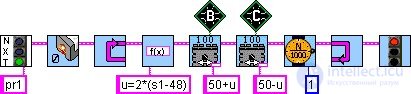
Fig. 8.39. Line-following algorithm with a single light sensor using a proportional controller.
The number 48, used in the control formula u, is the arithmetic mean of the light sensor readings on black and on white, for example (40 + 56) / 2 = 48. However, sensor readings often change for various reasons: a different surface, a change in the overall lighting of the room, a small modification to the design, and so on. Therefore it makes sense to teach the robot to calculate the arithmetic mean itself, that is, the value of the boundary between white and black.
There are several ways to calibrate the sensor. In the simplest case, instead of calculating the arithmetic mean, the white value is simply reduced. The idea of this method is that the robot takes a reading on white, subtracts some assumed value from it, and treats the resulting number as the boundary between white and black. For example, 56 – 7 = 49 can be taken as the gray value (fig. 8.40).

Fig. 8.40. Line-following algorithm with a single light sensor using a proportional controller with preliminary calibration (determining the gray value).
task main() { int u, v=50; float k=2; int red=SensorValue[S1]-7; while(true) { u=k*(SensorValue[s1]-red); motor[motorB]=v+u; motor[motorC]=v-u; wait1Msec(1); } }
By default, the light level from the sensor on port 1 is read into the red container, after which it is reduced by 7, and the control formula u uses the already modified value of the red container, red. If all the modifiers are specified, the program will look as shown in fig. 8.41.
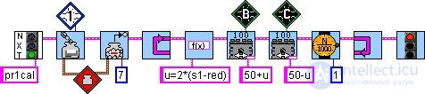
Fig. 8.41. Line-following algorithm with a single light sensor using a proportional controller — with modifiers.
Keep in mind that this calibration method does not account for all possible scenarios; it only saves time on programming and debugging. If there is enough time, there is another method that actually calculates the arithmetic mean of the light sensor readings on black and on white (fig. 8.42).
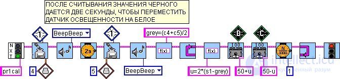
Fig. 8.42. Line-following algorithm with a single light sensor using a proportional controller with calculation of the gray value.
task main() { int u, v=50; float k=2; int c4=SensorValue[S1]; PlaySound(soundBeepBeep); wait1Msec(2000); int c5=SensorValue[S1]; PlaySound(soundBeepBeep); int grey=(c4+c5)/2; while(true) { u=k*(SensorValue[S1]-grey); motor[motorB]=v+u; motor[motorC]=v-u; wait1Msec(1); } }
The proposed algorithm has a certain inconvenience: when starting it, you need to pay attention and not miss the beep, after which the robot needs to be moved so that the light sensor ends up over the white field. Obviously, at the start the robot should be placed exactly over the black line. Container number 4 (denoted c4) will store the black value, and container number 5 (c5) will store the white value. The gray value, which is used in the controller, is placed into the grey variable. Right after the second beep, the robot will start moving.
Calibration can be made more controllable. To do this, after each data reading you need to insert a wait for some external event, for example pressing the touch sensor, a decrease in distance on the ultrasonic sensor, or simply pressing the NXT button.
Let's look at the simplest example with an additional touch sensor connected to the second port. It makes sense to start the program after carefully placing the cart with the light sensor over the black line (fig. 8.43).
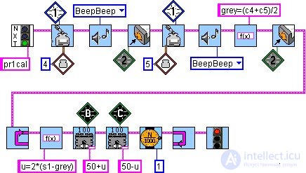
Fig. 8.43. Calibrating the light sensor while waiting for a touch.
task main() { int u, v=50; float k=2; int c4=SensorValue[S1]; PlaySound(soundBeepBeep); while(SensorValue[S2]==0); // Wait until pressed wait1Msec(100); // Debounce protection while(SensorValue[S2]==1); // Wait while pressed wait1Msec(100); int c5=SensorValue[S1]; PlaySound(soundBeepBeep); int grey=(c4+c5)/2; while(SensorValue[S2]==0); wait1Msec(100); while(SensorValue[S2]==1); while(true) { u=k*(SensorValue[S1]-grey); motor[motorB]=v+u; motor[motorC]=v-u; wait1Msec(1); } }
After the first beep, move the cart so that the light sensor ends up over white. After the second beep, get ready to start (light sensor on the boundary between black and white) and start by pressing the button.
A similar experiment can be carried out using a distance sensor instead of a touch sensor. The advantage here is that the robot will start contactlessly. This will help it start in an exactly chosen position. Just be careful not to pass your hand near the distance sensor at the wrong moment (fig. 8.44).
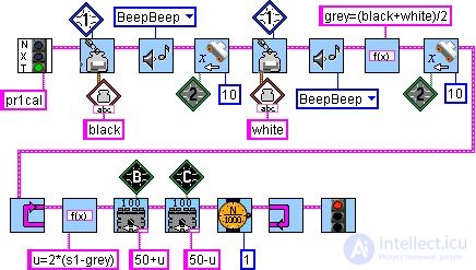
Fig. 8.44. Calibrating the light sensor while waiting for an object (a hand).
The example uses named containers (black and white), which are essentially variables, as in a regular programming language. Note that the beep between the two waits for a distance change helps prevent the robot from reacting twice in a row to a single approach of the hand.
The experience gained here is worth applying to finally push the pins out of the circle if any are still left on the boundary. Refine the algorithm given in fig. 8.31 on your own.
Field for line following
It's worth making a more interesting track than a circle yourself, on a light-colored surface of a fairly large area, using the same black tape. A sheet of plywood or hardboard, the back side of a linoleum sheet, white oilcloth, and many other materials will work as the surface. The field dimensions should preferably be no smaller than 100 · 150 cm. When laying out the track, allow a margin of at least 20 cm from the line to the edge of the field so that the robot's wheels don't run off the track during movement.
With a bit of skill, you can lay the tape so that it forms a closed curve. If it doesn't work with a single piece of tape, feel free to use scissors, making bends with a small radius of curvature out of several pieces. At first, it's best not to draw overly sharp turns. The line can be made from one, two, or even three strips of tape. This will make it easier for the robot to orient itself and stay on course. Besides electrical tape, matte black self-adhesive film can also be used. And finally, the optimal solution is printing a graphic file on banner fabric. The cost of such printing usually does not exceed 400 rubles per 1 m2. A small field for line following is shown in fig. 8.45.
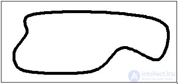
Fig. 8.45. Example of a homemade field for line following.
Fig. 8.46 shows an example track for competitions under the rules of the Open Tournament for the Polytechnic Museum Cup (Moscow). The line width is 5 cm, and the minimum radius of curvature is 30 cm. The current competition regulations are posted on the website http://railab.ru. The regulations for the "Line Racing" competition and the field itself in vector format can be found on the website http://myrobot.ru[11].
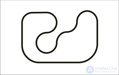
Fig. 8.46. Field for the "Line Racing" competition.
The quality and type of navigation system for a robotic device determine how quickly the robot will orient itself in space and how well it will perform its tasks.
The sensor system is divided into the following types
External sensors are needed to scan the surrounding space, avoid obstacles, and build an optimal route for movement.
|
Sensor type |
What it's for |
|---|---|
| Contact | For avoiding obstacles upon collision. |
| Non-contact | Detects an obstacle and allows the robot to stop before colliding. |
| Ultrasonic rangefinder | Works on the principle of echolocation and eliminates the possibility of hitting walls and furniture. |
External sensors help keep the robot intact and protect it from collisions with furniture or walls.
The most advanced type of spatial orientation, it makes it possible to build a map of the room. Special laser rangefinders measure the distance to walls and furniture and store the data in the device's memory.
They also help build virtual walls. A virtual wall ー is a way of dividing the space into zones where special work needs to be done, such as cleaning or painting, and the opposite zones, which robots do not need to visit.
Video cameras
The camera is mounted at the top, the highest point of the panel, and scans information from the walls, floor, ceiling, and furniture. Such a device moves in straight lines and moves from room to room in turn. Computer vision and image recognition algorithms can be used for this
First, let's learn to travel around it, if possible without bumping into objects and without getting stuck.
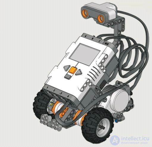
A suitable design for such a robot is a three-wheeled cart with an ultrasonic sensor mounted on top (fig. 8.78). This sensor should be positioned strictly horizontal relative to the floor, otherwise any speck of dust may be perceived as an insurmountable
obstacle, or conversely, something serious may go unnoticed.
Fig. 8.78. Small explorer from set 9797 with an ultrasonic sensor.
A simpler version of the design (fig. 8.79) can be built based on the cart discussed in chapter 3. The program's algorithm is very similar to that for traveling in a circle. Only the sensor changes (fig. 8.80).
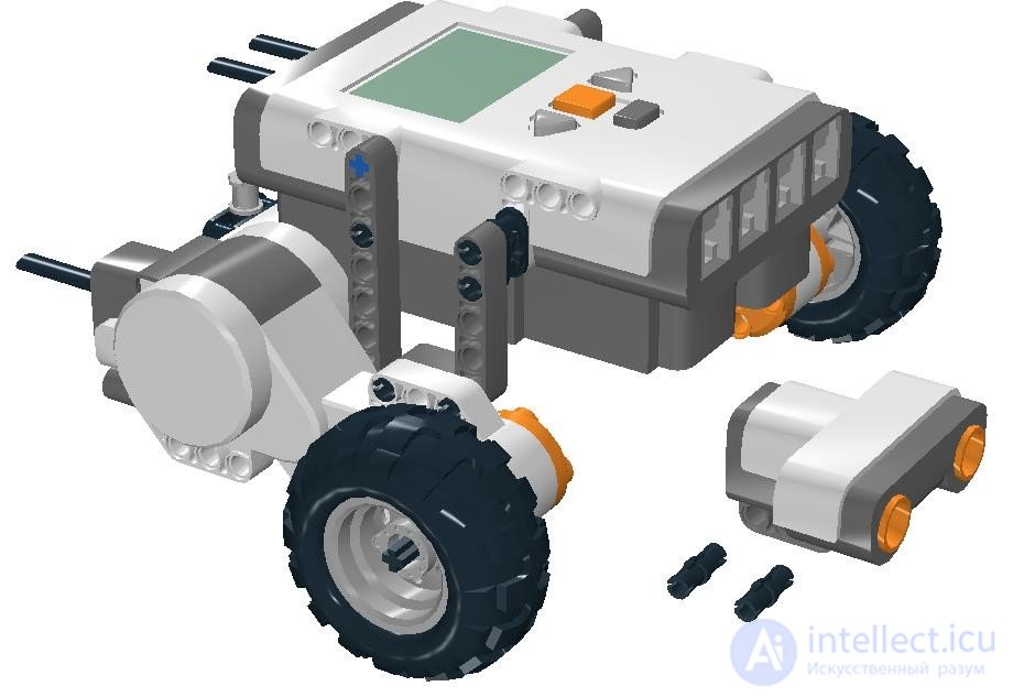
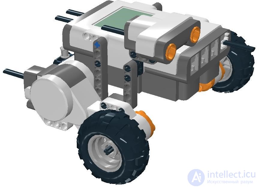
Fig. 8.79. The sensor attached to the cart's body must point strictly horizontally.

Fig. 8.80. Algorithm for traveling around a room.
It can be made a bit shorter if backing up with a turn in place is replaced by a single action: a smooth turn while reversing
(fig. 8.81).
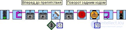
Fig. 8.81. Algorithm for traveling around a room with a reversing turn.
True, under some conditions such a turn can lead to a minor mishap, so be more careful with it. By the way, in both the first and second programs you should tune your own parameters for the distance to objects and the duration of turns.
Looking more closely at the robot's behavior, you can notice that not every object in its path falls within its field of view. For example, if an obstacle is low enough, the ultrasonic sensor may fail to detect it. Or a fabric-upholstered surface may simply absorb the ultrasonic signal, i.e. not reflect it back to the sensing element.
Without seeing the obstacle (a slipper or a chair leg), the robot may get stuck and keep trying to move forward indefinitely. However, if you think it through, you can conclude that motion in a room should not go on forever. Say, the robot can cross from one wall to the other in 10 s. If it doesn't see a single obstacle in that time, you can safely assume it has gotten stuck and emergency measures are needed. What should be done? Nothing special. Just back up and turn around. A "watchdog timer" (Fig. 8.82) will help with this. Such devices are used in microcontrollers to protect them from hanging.
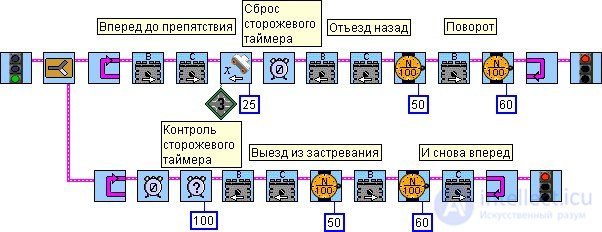
Fig. 8.82. If the watchdog timer "ticks up" to 10 s, the anti-stall protection kicks in.
You may notice repeating groups of blocks in our program. It makes sense to combine them into a subroutine that backs up and turns around (Fig. 8.83). This way, the backing-up subroutine will be called in two cases: 1) when there is an obstacle, 2) when the watchdog timer triggers.
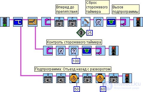
Fig. 8.83. Anti-stall protection using subroutines.
But this program has one significant drawback. Two parallel tasks access the same motors. If these accesses coincide in time, unpredictable robot behavior can occur. In a way, that's even interesting. But a more correct program is described in the next section.
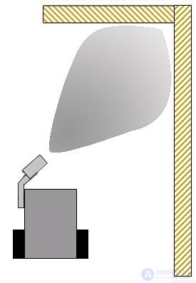
Fig. 8.89. The distance sensor is mounted at an acute angle to the direction of travel.
The first steps toward obstacle avoidance were made in the "Control algorithms" chapter. Following a wall with small deviations is possible using a PD controller. However, the robot described can only follow walls with small deviations from a straight line. With sharp bends, the robot may lose contact with the wall and start spinning in place. This problem can partly be solved through the design.
Let's consider a case where the robot's path involves major turns, all the way up to right angles. This will require modifications to both the design and the program.
First, the robot will need to look not only to the right but also forward. Installing a second rangefinder is fairly costly. However, we can take advantage of the fact that the ultrasonic sensor has a widening field of view
(Fig. 8.89). This is similar to a person's peripheral vision: you can catch something out of the corner of your eye. Taking advantage of this property, let's mount the distance sensor not perpendicular to the direction of travel but at an acute angle (Figs. 8.90, 8.91). This way we can "kill two birds with one stone." First, the robot will be able to see obstacles ahead; second, it will hold its course along the wall more stably, constantly staying at the edge of visibility. This way, without adding any new devices, we can use the rangefinder's capabilities more effectively.
Important note. When the robot starts, it must be aimed with the sensor pointing straight at the wall so that the initial reading is taken without interference.
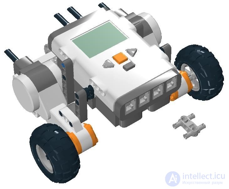
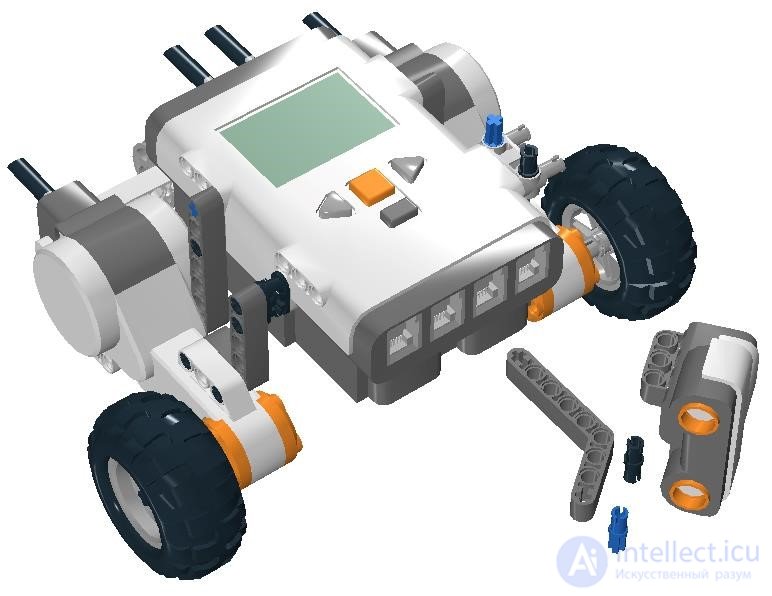
Fig. 8.90. The mount is placed on the left side. As in the first design, the sensor is oriented vertically.
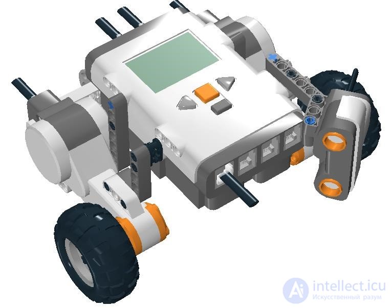
Fig. 8.91. The distance to the wall, increased by the robot's body, helps widen the field of view.
Obviously, changing the design changes the controller coefficients k1 and k2. Tuning usually starts with the proportional coefficient at a zero differential term. Once some stability is achieved at small deviations, the differential term is added.
The next step is to limit the robot's reaction to "infinity." As is known, when there is no object in view, the NXT distance sensor reads 250 or 255 cm. If this number is fed into the proportional controller, the robot starts spinning in place. And that's exactly what will happen in a situation where the robot needs to turn a corner.
To go around objects, we need to add monitoring of the distance sensor's readings: on a sharp change, the robot should conclude that a turn is possible and needs to be executed with different coefficients, or simply with a constant control output value.
Let's consider an example of turning right "around a corner" (Fig. 8.92). If the robot moves at a distance L from the wall, then it will obviously make the turn along a circle of radius L.
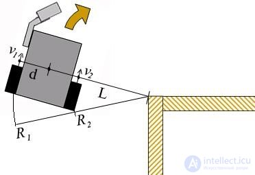
Fig. 8.92. Executing a turn after losing contact with the wall.
It is easy to calculate what the ratio of wheel speeds should be for the turning radius to equal L. To do this, it is enough to measure the distance between the front wheels. Let's say in our robot it equals k = 16 cm, and half of that, d = 16 / 2 = 8 cm. Then the left and right wheels move along circles of radii, respectively, R1 = L + d and R2 = L – d. The distances they cover per unit of time must be proportional to the radii, so the speeds of the wheel mounting points v1 and v2 are related as follows:
v1 = R1 . v2 R2
Expressing the wheel speeds in terms of the base speed v and the unknown x, and the radii in terms of L, we get the following: v + x L+d
= , vL+xL-vd-xd =vL+vd-xL-xd , 2xL=2vd , v - x L-d x = vd, v1 = v + vd= v(1+ d), v2 = v - vd= v(1- d).
L L L L L
The linear speed v is proportional to the wheel's angular speed ω, which in turn is proportional to the power delivered to the motors (in braking mode). We have brought the control law to a standard form, which lets us set the control output for the duration of the corner turn. This gives us the calculation for controlling our robot's motors.
u=v*8/L; motor[motorB]=v+u; motor[motorC]=v-u;
When the distance to the wall becomes greater than 2L (we use this as the visibility threshold), i.e. a corner turn opens up, the control output starts being computed using the formulas given
(Fig. 8.93).
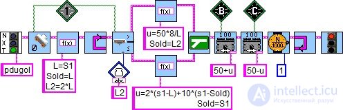
Fig. 8.93. Obstacle avoidance at a set distance, using the right-hand rule.
task main() { float u, k1=2, k2=10; int v=50, d=8, Sold, L, Snew; Sold=L=SensorValue[S1]; // Remembered the initial state while(true) { Snew=SensorValue[S1]; // Got the sensor reading if (Snew>L*2) { u=v*d/L; Sold=L*2; } else { u = k1*(Snew-L) + k2*(Snew-Sold); Sold=Snew; } motor[motorB]=v+u; motor[motorC]=v-u; wait1Msec(1); } } task main() { float u, k1=2, k2=10, a=0.2, Snew; int v=50, d=8, Sold, L; Snew=Sold=L=SensorValue[S1]; while(true) { Snew=(1-a)*Snew+a*SensorValue[S1]; if (Snew>L*2) { u=v*d/L; Sold=L*2; } else { u = k1*(Snew-L) + k2*(Snew-Sold); Sold=Snew; } motor[motorB]=v+u; motor[motorC]=v-u; wait1Msec(1); } }
Data filtering becomes especially important when it needs to be the basis for deciding on further long-term actions. For example, seeing an opening and stopping or turning back. A single spurious reading is enough for the robot to stop in the wrong place. That's why filters, even though they slow down the robot's reaction, make it more stable and predictable.
Robotic vacuum cleaner — a vacuum cleaner equipped with artificial intelligence (an ordinary, non-thinking automaton) and designed for automatically cleaning rooms. It belongs to the class of household robots and smart-home intelligent appliances.
Since the early 2000s, many companies have started producing "robotic vacuum cleaners," such as the Electrolux Trilobite, Roomba, Samsung Navibot, Okami, and others.
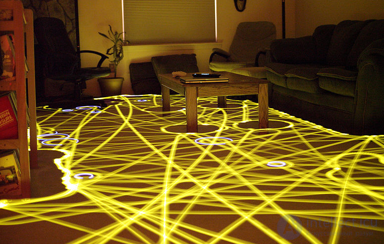
Figure: A long-exposure photograph showing the movement pattern of a robotic vacuum cleaner
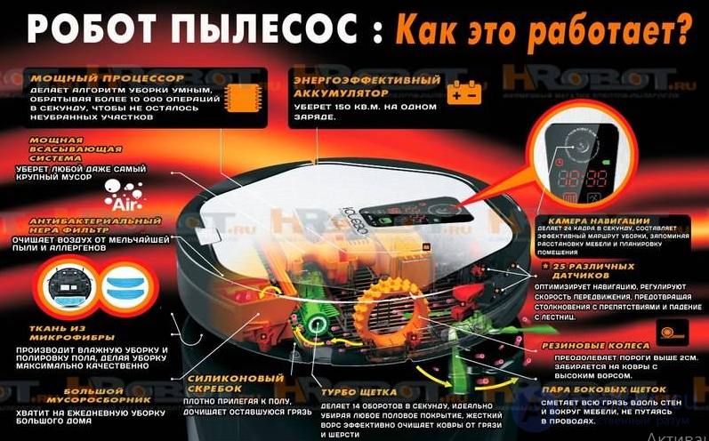
A modern device is most often shaped like a disk 28-35 cm in diameter and 9-13 cm tall. The front of the robot usually has a "bumper" — a large contact sensor that the robot uses to detect collisions with obstacles. Inside the "bumper" there are usually non-contact obstacle-detection sensors (consisting of an infrared light source and a reflected-signal-level detector).
To protect against falling down stairs, the underside of the robot near the wheels usually has 4 or 6 non-contact sensors installed (consisting of an infrared light source and a reflected-signal-level detector) pointing downward and placed next to the robot's wheels. Because of how these sensors work, robots perceive black surfaces (most often rubber mats) as an impassable obstacle (thinking there is a drop-off in front of them).
To operate, a robotic vacuum cleaner uses internal batteries (Ni-MH, Li-ion, and LiFePO4) and needs to be recharged regularly from a special module — the "Base" (the robot also often has a socket for manual charging, but this option is usually not used). Most models can find the "Base" on their own and dock with it once cleaning is finished. Charging takes about 2-5 hours (depending on the battery type and capacity).
During cleaning, the robot moves autonomously across a given surface, picking up debris from it. When it encounters an obstacle in its path, the robot decides how to overcome it based on special algorithms.
Probably everyone who is just starting to get seriously into robotics, electronics, or programming, going through the difficult path of learning the related technologies, hopes to one day apply the knowledge gained to a serious and interesting project.
For example, after reading a robotics forum, I decided to build a robot vacuum cleaner. The reason for this choice was not so much the usefulness of the device itself, but the fact that, in designing it, I could focus on a specific task: a robot capable of autonomously cleaning up debris with minimal maintenance.
This article is not a detailed description of how to build and set up the robot. In it, I mainly wanted to share the experience I gained while doing this work.
Mechanics:
Of all the mechanics of the robot vacuum cleaner, the debris-collection unit is the most challenging to design and build.
It must:
-Take up as little space as possible, while still having a roomy debris container.
-Clean dirt well on any surface, while having low power consumption and a low noise level.
Before I managed to satisfy all these requirements, I tried out many different variations of the unit's layout.
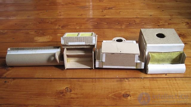
Mockups of debris-collection units.
In the end, I settled on a scheme: a wide side brush + a vacuum. The radial brush, located on the right side, rakes debris toward the vacuum's intake, located in the center. I decided not to install a horizontal cylindrical brush like Roomba's, since it only slightly improves cleaning quality while significantly complicating the design of the vacuum intake. The design of the vacuum unit is shown in the photo below.
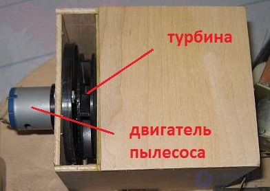
Outside.
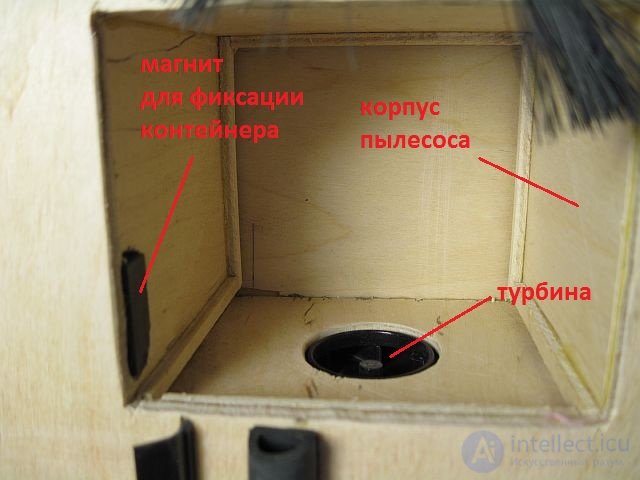
Inside.
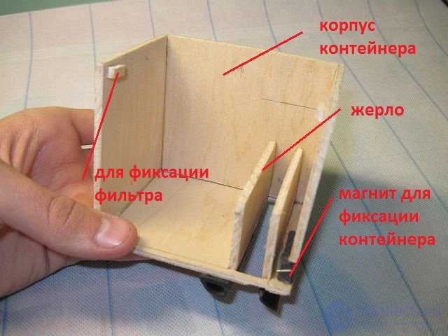
Container.
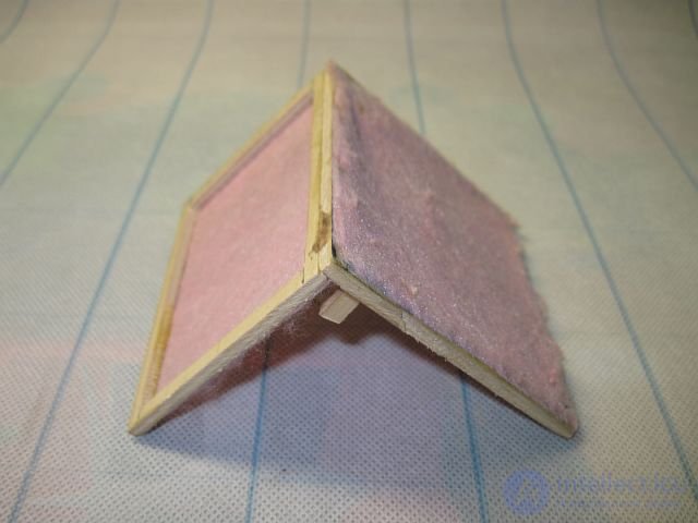
Filter.
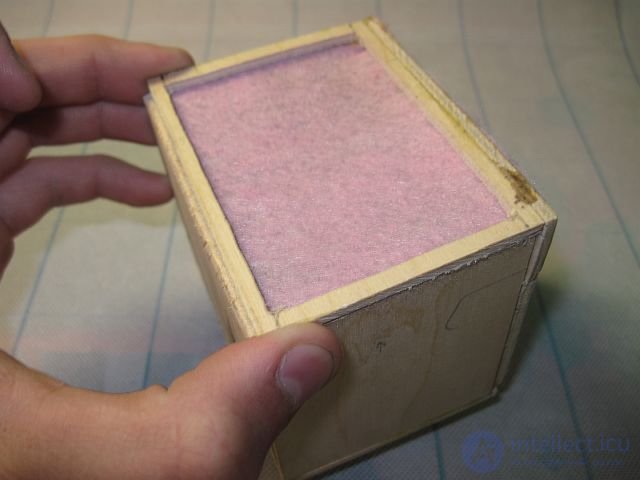
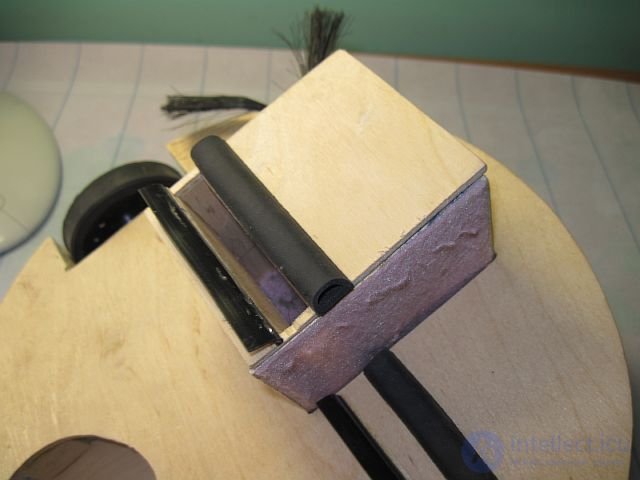
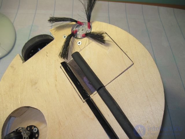
Assembly.
However, a question arises: where do you get a turbine and a motor for the vacuum?
Turbine can be soldered together from fiberglass PCB and tinplate;
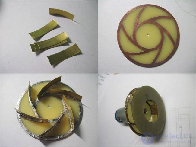
Tinplate turbine.
You can take a ready-made turbine from a large vacuum cleaner, first trimming it on a lathe.
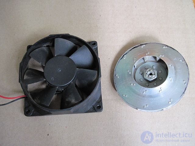
A ready-made turbine, trimmed on a lathe down to the needed diameter (a computer fan shown for comparison).
Or you can just buy one, in the form of a cheap Chinese car vacuum cleaner.
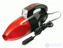
Vacuum cleaner.
Don't take this as an ad, but I recommend getting this particular vacuum (kioki), since it's guaranteed to have the right turbine with a powerful motor and a convenient mount (at an average price of 500 rubles). Although, as for the motor – it's better to replace it. The stock one draws around 3A; replacing it with a QX-RS-385-2073 motor drawing 1.2A, suction power drops only slightly, but the robot becomes quieter and runs longer without recharging. As for homemade turbines, although they suck well, it's quite hard to center them so there's no vibration.
The side brush is built from a tape-recorder motor connected to a ratchet shaft (taken out of a toy screwdriver) through a worm gear. The bristles were pulled out of a floor mop and fixed to a fiberglass-PCB disk with instant glue.
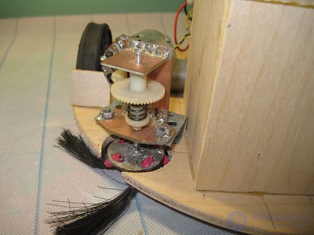
Radial brush.
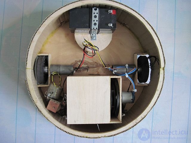
Two 25-millimeter gearmotors serve as the drive motors; something more suitable is probably needed here, such as servos converted for continuous rotation, but I used what was on hand.
There were no ready-made wheels of the right size, so I had to cut them out of 10-millimeter plywood and cover them with heat-insulating tape for better grip on the surface. The holes in the wheel are for encoders, although in the end I gave up on using them due to their low accuracy.
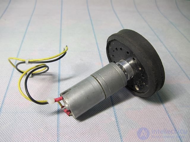
Wheel drive unit.
It's advisable to mount the drive units on an independent suspension. In this modification of the robot, I decided to check whether it's really needed, by installing the motors without suspension; as a result, problems arose when driving onto a thick carpet. The motor axles should coincide with the diameter of the robot's circle, which makes it easier to implement turning in place.
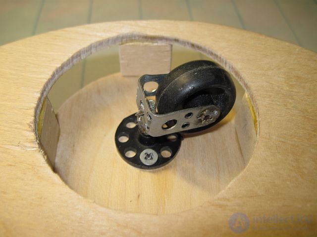
Steering wheel.
The collision sensor (hereafter, the bumper) is made from two switches and a strip of plastic bent into a semicircle, suspended on them.
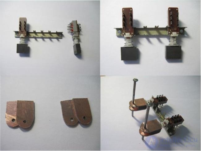
Switches
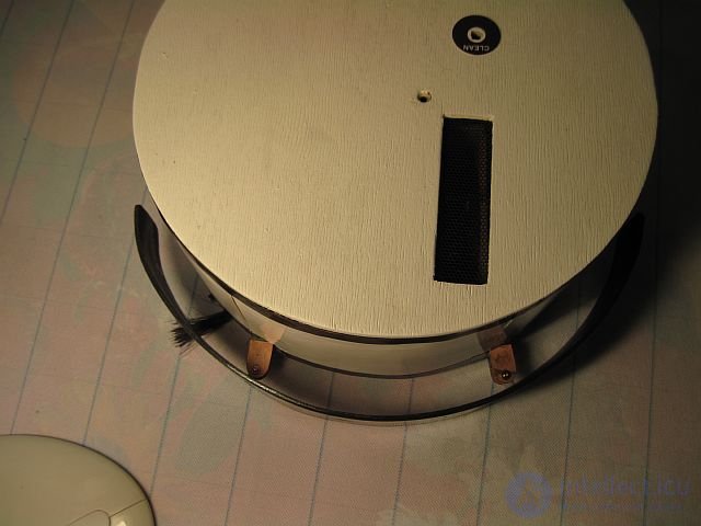
Bumper.
Normally the bumper should cover the entire front of the robot from top to bottom, but since all my furniture is the same height, I didn't bother with that.
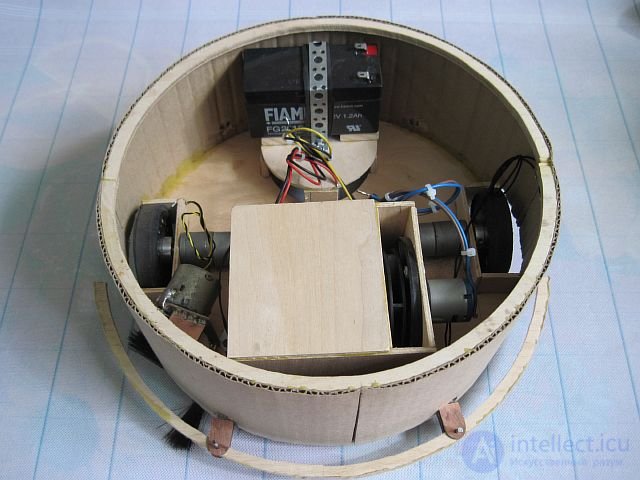
The robot's mechanics fully assembled.
To test the robot's mechanical part, the following simple control circuit was built:
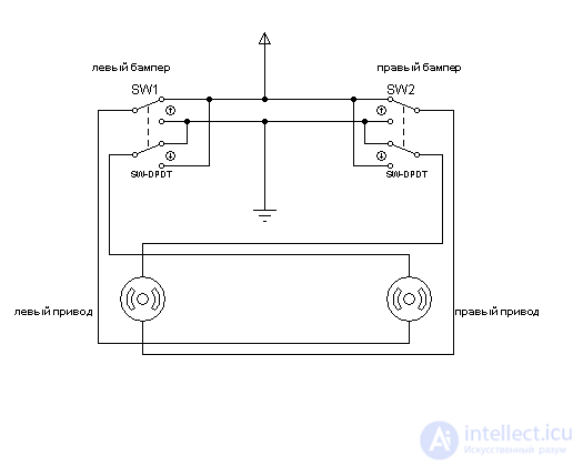
Control circuit.
Testing the mechanics with a simple cleaning algorithm:
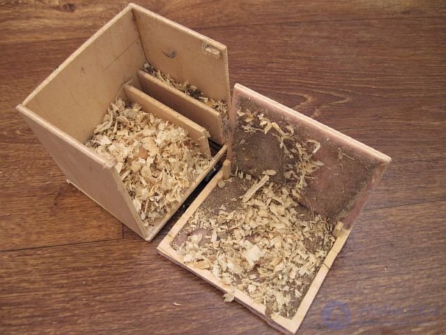
Container after cleaning.
As you can see, the debris-collection unit handles its job well, but when using a simple obstacle-avoidance algorithm, the robot follows the same path over and over, leaving a lot of missed spots.
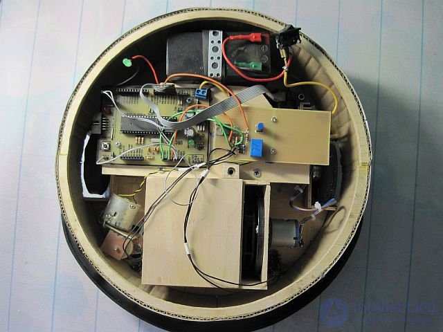
At the end of the first part of the article, the electronic circuit of a simple control algorithm was presented. In this part, we'll look at the electronic and software components of the robot's control system, based on a microcontroller.
Electronics:
The control board is built around an atmega16 microcontroller; it was originally designed as a universal module, so it turned out to be poorly protected against interference from the turbine motor. The problem was solved by shielding the motor wires and installing a 0.1uF capacitor on it; you also need to tie the controller's RESET pin directly (without a resistor) to +5V, which gets rid of random resets.
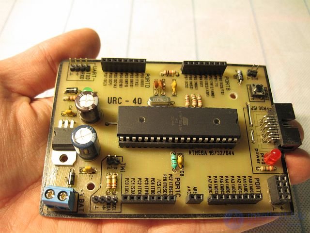
Controller board.
The motor driver is built on an L298 chip, following the standard circuit.
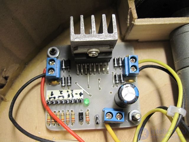
Motor driver board.
The rest of the electronics and controls are mounted on a breadboard.
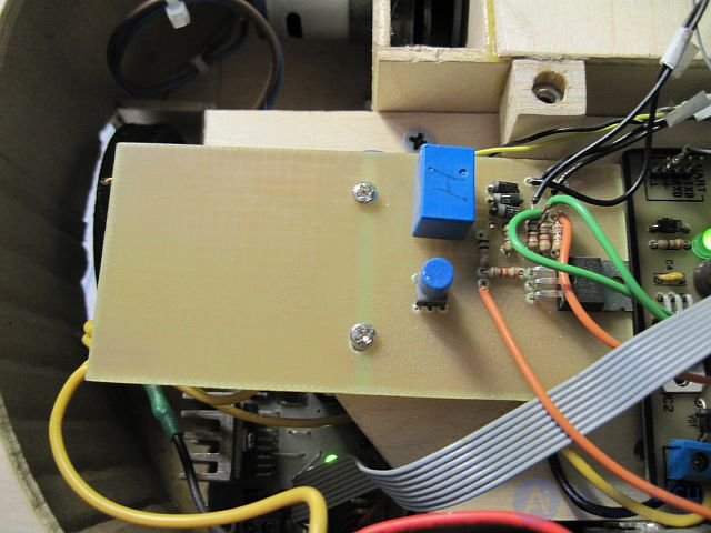
Breadboard.
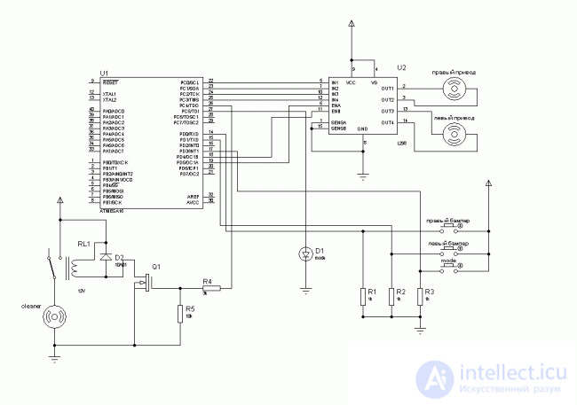
Overall electronic circuit.
As you can see, the circuit doesn't include a battery-charge monitoring device or sensors for finding the charging station. All of that was present in the previous modification of the robot and worked pretty well, but since it turned out a bit rough around the edges and needs further work, I won't describe those missing elements in this article. However, so as not to just take my word for it, here's a video of the previous robot modification searching for the charging station.
Searching for the charging station
Program:
Probably the most interesting part of the whole project is creating the algorithm and writing the robot's control program.
The cleaning algorithm is split into 4 modes:
•Standby mode
•Spiral
•Wall following
•"Lawnmower"
Let's look at each of them separately.
Standby mode
Here everything is simple: the drive motors are off, the turbine and brush are off too, the indicator blinks at a low frequency, there's no reaction to the bumper triggering, and pressing the button switches to the next mode.
Spiral
This algorithm works well for rooms with a minimal amount of furniture. After detecting an obstacle, the robot switches to the next mode, since that obstacle is most likely a wall, so it makes sense to switch to wall-following mode.
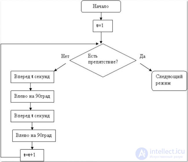
In the flowchart, the obstacle check is shown as a single step for simplicity, but in the program it's actually performed continuously, not just once per iteration.
Wall following
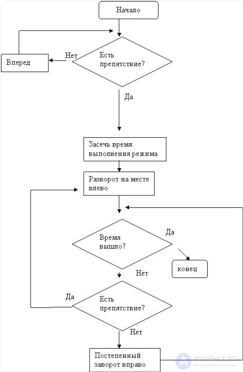
In my opinion this is the most essential algorithm in a cleaning robot, since most of the dust and debris collects right along the walls. In the first stage, the robot moves forward until it detects an obstacle, and then switches to moving alongside it. Since that obstacle could turn out to be not just a wall but really anything at all (for example, a chair leg), the mode's operation must be time-limited to avoid getting stuck in a loop.
"Lawnmower"
This algorithm was suggested on the robotics forum and tested in the Logo environment. It's a good replacement for random wandering, as you can see by running the algorithm in Logo on a model of your own room:
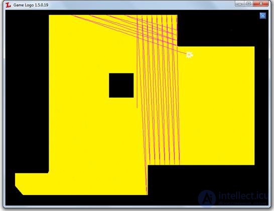
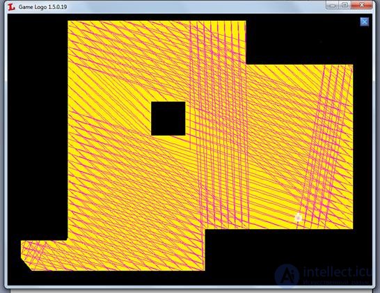
Of course, in real conditions it's not quite as ideal, but on the plus side, this cleaning algorithm only needs collision sensors among all the sensors.
I won't give a flowchart for this algorithm; the robotics forum has the Logo code.
The program was written in plain C with no asm inserts.
The code is split into several parts:
main.c - the file with the main function and the main loop.
Periphery.c - hardware dependencies, controller peripheral setup.
Action.c - the functional part of the program
util/drivers.c - device control functions
util/timer.c - timer service
Periphery.c
Contains only one function — Periphery(), which configures the controller's peripherals. The function is called once, from the program's main function.
util/drivers.c
Contains macros for controlling the cleaning unit:
#define ON_Cleaner PORTC |= (1<<4) #define OFF_Cleaner PORTC &= ~(1<<4)
As well as a function for controlling the drive motors:
void M_drive(signed char l_vector, char l_speed, signed char r_vector, char r_speed);
*_vector – the motor's rotation direction: 1-forward, 0-stop, -1-backward
*_speed – rotation speed, a number from 0 to 10
util/timer.c
Contains two functions:
void Timer_ControlTimer(void); //timer service
The function that handles time delays. It is called only on an interrupt from timer-counter 2, every 1/1000 sec.
void Timer_Task(int *Time); //adds a task to the timer queue
The single parameter passed is a pointer to the variable that the time will be counted down from. The variable must be pre-initialized with some value other than zero. As soon as the variable's value reaches zero, the pointer to it is removed from the timer queue. The length of the timer queue can be set using the SIZE_ARRAY_HOURS macro. Note that the Timer_Task function is not an analog of the _delay() function, since it returns control immediately; you have to check manually whether the timer has finished counting. For example, here's what the delay handling looks like in the indicator control function:
     void led()     	{
	if(led_time!=0)
    //if the time hasn't come yet
{
return;
		}
   	if(Mode>0)
    //if cleaning
	{
	if(PORTC & (1<<5))
		{
PORTC &= ~(1<<5);
	     			led_time=300;
     //turn off for 0.3 sec
	Timer_Task(&led_time);
	}     		else     			{     			PORTC |= (1<<5);     			     			led_time=200;	       //turn on for 0.2 sec     			Timer_Task(&led_time);     			}     		}     	else			               //if standby mode     		{     		if(PORTC & (1<<5))     			{     			PORTC &= ~(1<<5);     			     			led_time=1000;     			Timer_Task(&led_time);	//turn off for 2.5 sec      			}     		else     			{     			PORTC |= (1<<5);     			     			led_time=1000;     			Timer_Task(&led_time);	//turn on for 1 sec     			}     		}     	}
Action.c
The functional part of the code is split into modules; a separate module is written for each physical or software device. Physical devices:
-Drive
-Control button
-Indicator
-Vacuum
Software device:
-Cleaning cycle control.
Modules perform different work depending on the current mode. The program inside them is organized as a finite-state machine, using a switch-case construct. Modules can interact with each other through global variables or by changing each other's state-machine counters.
The module functions are called from the program's main loop:
     int main(void)
	{
	Periphery();
//peripheral setup
	//program's main loop
	while(1)
{
	button();
   //mode-button handler
	cycle();
  //cleaning cycle control
	drive();
  //drive
cleaner();
 //cleaning unit
	bumper();
  //bumper
led();
  //operating-mode indicator
		}
	}
I won't describe how each module works; there are enough comments in the code for anyone who wants to understand it.
Action.c also has the util_mode(char _mode) function, which is used to switch the operating mode. Besides assigning a new value to the Mode variable, the function definition also resets the state-machine counters and the timer variables.
     void util_mode(char _mode)
	{
	if(_mode>=AMOUNT_MODE)
//if that mode doesn't exist
 		{
Mode=0;
	}
else
{
	Mode=_mode;
  		}
//reset variables and counters
 	drive_counter=0;
bumper_counter=0;

    	drive_time=0;
	led_time=0;
}
Source code https://github.com/IvanFeofanov/robot_cleaner/
The project is built with the avrGCC compiler; a Makefile is included.
Conclusion:
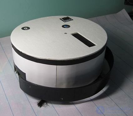
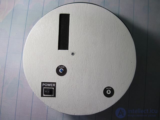
The robot fully assembled:
Testing:
As you can see, the robot handles its job quite well. The way the program is organized makes it easy to extend the device's functionality by adding the missing modules: battery-charge monitoring and charging-station search. Otherwise, the robot is already quite suitable for everyday room cleaning.
Sensors, sensors

Comments