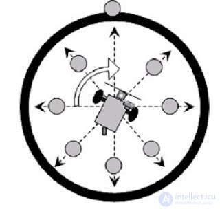
The algorithm for the robot’s motion along this trajectory is often called "Dance in the Circle." The robot must push all the pins out of the circle in the shortest possible time, while never leaving the circle itself.
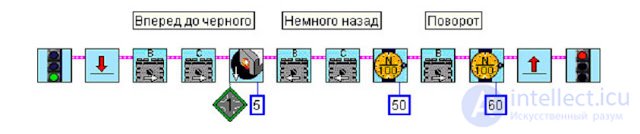
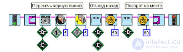
The first version of the program in the Robolab language illustrates the simplest algorithm for moving inside a circle bounded by a black border. The direction of motor rotation depends on the light sensor readings. A value of 5 in the blue (numeric) modifier means waiting for the light level to become 5 points darker than the current one.
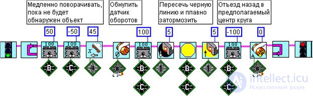
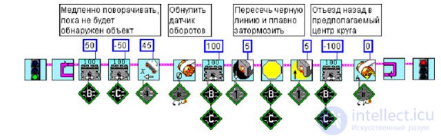
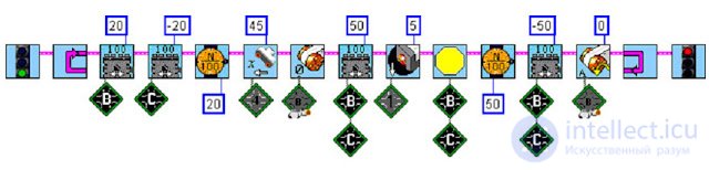
The second example program is somewhat more complex. Now the initial position of the pins is unknown, and the robot has to search for them on its own. The search uses a distance sensor (sonar), whose reading must be 45 cm or less at the moment of detection. This time, for greater accuracy, the motors are rotated not by time but by a set number of rotations in each direction. The light sensor is still used to detect the black line.
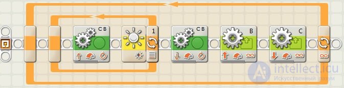
In the NXT-G language, a simple algorithm for the Kegelring task might look like this.
Here the same algorithm is implemented as in the Robolab program. The movement block that follows the loop runs for three motor rotations. This is quite enough for the robot to move away from the line to turn around. The last two Motor commands make the robot turn around its own axis. Check the turn time carefully! The robot must turn to face the inside of the circle with its front in order to continue searching for the remaining pins. The exact turn time can be determined experimentally.
An example implementation of a more complex algorithm with pin search.
The command parameters are set the same as in the Robolab program. Instead of wait commands, loops are used, which reduces the overall efficiency of the program but makes it easier to understand the algorithm itself by considering several variants of its implementation.
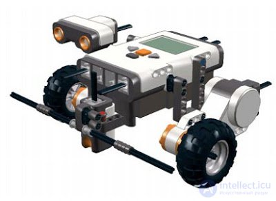
The robot lives inside a circle that it must not leave. To complete this task you need to build a standard three-wheeled cart: two front driving wheels, and one rear caster wheel on a swivel joint. A light sensor is mounted at the front center, pointing straight down, at a distance of 5-10 mm from the floor.
The robot is placed in the center and, at the start, must move within the circle without going beyond its boundaries.
The algorithm for the "Dance in the Circle" is as follows:
- drive forward until the sensor reading drops by 5 points (10 is better);
- back up a little (half a second);
- turn about 120-150 degrees (also timed);
- repeat steps 1-3 indefinitely.
Set the parameters in the modifiers yourself: the amount by which the light level drops on the black line, the time to back up, and the turn time.
Push Out All the CansSeveral plastic cups or empty tin cans are placed inside the circle, 12-15 cm behind the black line - this is the trash that must be cleared from the circle in the shortest possible time. The first attempts to run the robot will reveal several
shortcomings:
- cups get caught under the wheels, fall over, and are pushed out poorly;
- even pushed-out cups remain partially inside the circle, because as soon as the robot sees the edge it immediately darts back;
- the robot behaves like a bull in a china shop;
- the robot makes a lot of wasted movements.
Let's get rid of the first shortcoming. To do this, we'll build a bumper 20-25 cm wide next to the light sensor.
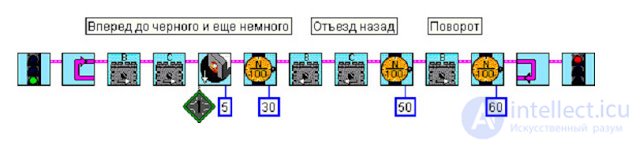
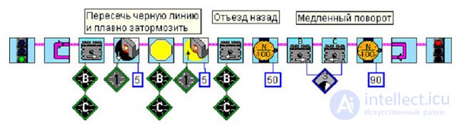
The second and third shortcomings are eliminated in software. Let the cart, upon seeing the edge, move forward a little more, pushing the cup out, and only then turn back into the circle.
The most reliable way to stop exactly at the edge of the black line is to wait for the light sensor to read white. So the timed wait can be replaced with "wait for white." To save space, it’s worth grouping the motor control commands together, and also using "reverse" when changing direction on running motors.
Now it's worth working on movement accuracy, without losing speed if possible.
Depending on the robot’s design, a sudden change of direction may cause it to lose balance or simply "rear up" on its front wheels. So the last few centimeters can be covered by coasting to a stop, that is, with the motors completely released.
And second: turning accuracy will depend on which commands are sent to the motors and on what principle the turn durations are calculated. Unfortunately, a timer is not a reliable helper. Due to inertia, over short time intervals the robot may end up turning through varying angles.
We can sacrifice the reverse in the last command controlling motor B, in order to achieve slower, more careful motion with both motors together. The turn duration will increase slightly.
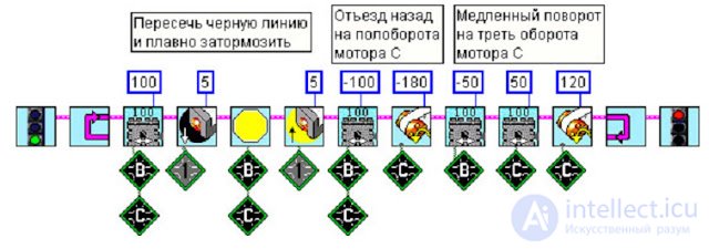
In order to control the motors more precisely, a different type of command must be used: one with controlled rotation. These commands are found in the "Advanced Output Control" section and allow the motor power to be set from -100 to 100. In the new example, for compactness, we’ll place all the numeric parameters at the top and the port modifiers at the bottom.
Avoid Unnecessary MovementsThe desire to keep the robot's movement under control leads to the need to change the motion path so that every time it reaches the edge, it returns to the center of the circle.
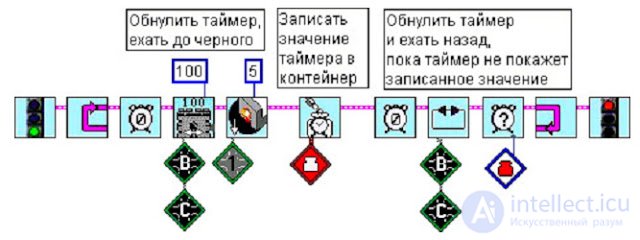
NXT servo motors have a built-in rotation sensor, and it should definitely be used. To do this, the rotation sensor reading must be reset to zero when the robot is at the center. Time cannot be turned back to return to the zero point, but the motors can be. The idea is that the robot drives forward a certain number of rotations, then goes back until the rotation sensor reads zero again.
In Robolab, this requires using a specific block that does not reset the rotation sensor readings on call (marked with the letter A on the icon). In addition, the example adds "Encoder C" modifiers from the "NXT Commander" palette to make it clearer to distinguish between motor control commands and sensor readings.
The result is already much better, but the robot still sometimes misses the pins. Of course it does - it's turning blindly. It should be equipped with vision. A distance sensor is suitable for this. The sensor should be mounted so that the right-hand sensor (as seen from the connector side) leads the direction of travel. That way, during rotation there's a greater chance that the reflected signal will be picked up by the receiving eye that follows behind.
So, the rotation continues until the distance sensor receives a signal, for example, "closer than 45." That is, an object has been detected at a distance of less than 45 cm. Keep in mind that the robot should not pay attention to cups it has already pushed out past the line. So the specified distance should not be made greater than the radius of the circle.
Depending on the robot's design, the algorithm described above may have one drawback. Having returned to the center of the circle, the robot starts rotating until a pin appears. However, due to the inaccuracy of the ultrasonic sensor, it may react immediately to a pin that has already been pushed out. So it makes sense, first, to push the pins further out beyond the circle; second, to start the turn blindly; and third, to perform all actions at a slower pace at first.





Comments