
Lecture
Memory plays an important role in robotics, as it allows robots to store and retrieve information, make decisions, and perform tasks. Several types of memory are used in robotics, each with its own characteristics and applications. Below are some of them:
Random-access memory (RAM): RAM is used for temporary storage of data that the robot uses during operation. It allows fast reading and writing of data, but the information in RAM is lost when the robot is powered off. RAM is used, for example, to store the robot's current state, intermediate calculation results, and temporary data.
Persistent memory: Persistent memory, such as flash memory or a hard disk, is used for long-term data storage. In robotics it can be used to store software, system settings, environment maps, and other important data. Robots can load data from persistent memory at startup or during operation.
Episodic memory: Episodic memory is a mechanism that allows a robot to store experience or sequences of events for later use. It can be used to train the robot based on experience or to replay previous scenarios. Episodic memory can be implemented using various algorithms and models, such as recurrent neural networks or reinforcement learning methods.
Cache memory: Cache memory is used for temporary storage of data that the robot accesses frequently. It speeds up access to this data, since the cache is located closer to the processor or controller than main memory. Cache memory can be built directly into the processor or used at the system level.
The use of memory in robotics depends on the specific tasks and requirements of the robot. Robot developers must take into account the amount of available memory, the speed of data access, the retention of information during power loss, and other factors in order to make efficient use of memory and ensure reliable operation of the robot.
Buffer storage devices, also known as buffers, are used for the temporary storage of data during the transfer or processing of information, and are intended for the intermediate storage of information when it is exchanged between computer devices operating at different speeds. They play an important role in robotics and in computer systems in general. Structurally, a buffer can be part of any of the functional devices. Here are some examples of buffer storage devices:
RAM buffers: RAM buffers are used for temporary storage of data before it is processed or transferred to other devices or subsystems. They smooth out differences in the operating speed of various system components and also enable more efficient use of resources.
Input/output buffers (I/O buffers): I/O buffers are used for temporary storage of data transferred between input/output devices and the main system. They help reconcile the difference in data-exchange speed between devices and also prevent data loss during temporary delays or overloads.
Disk cache buffers: A disk cache is a buffer memory area used for temporary storage of data that will be written to or read from a hard disk. The disk cache speeds up data access, since read and write operations can be performed faster using the buffer than directly with the disk.
Buffers in network communications: Buffers are also used in network communications for temporary storage of data packets before they are sent or processed. Buffers in network devices, such as routers or network cards, smooth out differences in throughput and enable more efficient data transfer.
Buffer storage devices help reconcile differences in the operating speeds of various system components and also provide a more stable and efficient data flow.
Described below is a buffer storage device (BSD) that reads an image from a television camera (TV camera), implemented on a photodiode array (Fig. 2.28).
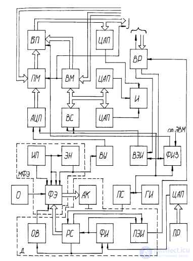
Fig. 2.28. Buffer storage device on a photodiode array for reading medium-format grayscale images
The BSD contains the following units: L - lens; PE - photosensitive element; APE - array of photosensitive elements; AS - analog switch; OS - one-shot (monostable multivibrator); SR - shift register; PF - pulse former; PSU - power supply unit; FAE - first AND element; SAE - second AND element; LE - load element; VA -
video amplifier; FC - first counter; SC - second counter; PG - pulse generator; FR - first register; SR2 - second register;
WPF - write-pulse former; FM - first multiplexer; SR2 - second multiplexer; MB - memory block; ADC - analog-to-digital converter; DAC - digital-to-analog converter; I - indicator (video monitoring device).
The BSD operates as follows. The image of the selected area of the working zone is projected onto the photosensitive field of the PE by means of lens L. The conversion of optical information into an electrical signal is performed using FC, SR, and AS by sequentially reading the signal from each PE of the array row.
The required operating frequency of AS, SR, and FC is set by the PG.
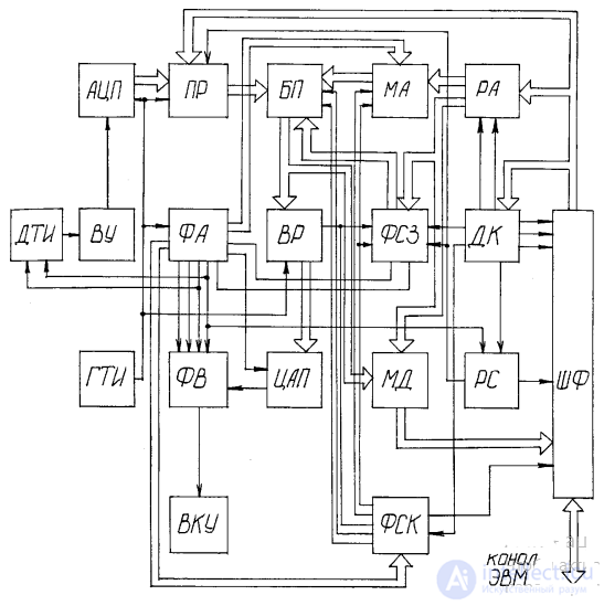
Fig. 2.29. Buffer storage device for reading medium-format grayscale images
After the last PE of the last row of the array has been read, the OS "clears" the APE cells. The PF provides the accumulation time of video information for the APE, set by the FR through the DAC.
The FR also has an input for performing a "reset" operation. The video signal taken from the LE (connected, like the PE, to the PSU) is digitized by the ADC. Information is written to the MB on command from SR2 (via the WPF), which decodes commands arriving over the bus from the computer.
The address in the MB is set by the SR2, and the write and reset modes of the MB are controlled by the WPF and SAE. In display mode, information (about the coordinates of the array cell) from the SC is passed through the corresponding DAC to the indicator I, whose third input receives the video signal from the DAC. When outputting information to the computer (to the indicator), an "output" command (from the computer) is sent to the WPF, which forms a write pulse fed to the MB. In doing so, the FM and SR2 are controlled accordingly. Thus, the BSD makes it possible to read (into memory and then into the computer) a small-format grayscale image (32×32), display the image on the indicator, and output the processed image from the computer to the indicator screen.
Further development of the BSD has led to devices that read medium-format images (256×256) and work with television cameras using a CCD array or vidicon. A variant of such a BSD is described below. The device contains the following units (Fig. 2.29): TIS - TV-image sensor; VA - video amplifier; ADC - analog-to-digital converter; CPG - clock pulse generator; FR - first register; WSF - write-signal former; AF - address former; MB - memory block; SR2 - second register; DM - data multiplexer; DAC - digital-to-analog converter; VF - video former; SR - status register; AM - address multiplexer; CSF - command-signal former; CD - command decoder; AR - address register; BF - bus former; VMD - video monitoring device.
The operating principle of this BSD is largely similar to that of the previous device. The BSD has four modes: a mode
for monitoring the information written in the memory block, a frame-writing mode, a mode for reading information from the memory block into the computer, and a mode for writing information from the computer into the memory block. In its initial state the device is in monitoring mode. The other three modes can be switched on at the required time using the computer. After finishing writing a frame or exchanging information with the computer, the device automatically switches back to monitoring mode. Video information from the TIS is written into the MB via the VA, ADC, and FR. Writing a frame of the image into the MB is controlled by the computer through
CD, SR, WSF, and FR. Here the FR converts serial digital information into parallel form. During the conversion of serial information into parallel form, the CSF sends the signals to the MB needed for writing, and the AF, which generates a 14-bit address, uses the AM to sequentially switch (seven bits at a time) the address inputs of the MB. The FR, AF, and WSF are synchronized by a signal coming from the CPG. At the end of a half-frame, when the next frame sync pulse arrives at the SR, the register removes the signal from the WSF and FR, and the BSD automatically switches to
monitoring mode.
In monitoring mode, information about four picture elements is read in parallel from the MB, and then, using SR2, the parallel combination of numbers is converted and fed to the DAC, whose output signal is summed by the VF with the sync pulses and blanking pulses coming from the AF. On command from the CD (to the CSF and BF), information is read from the MB into the computer via the DM and BF. Here the DM selects signals, depending on the two least significant bits of the column address, from one of four groups of MB chips. The address for reading is set by the AM, using information from the AR.
When writing data into the MB from the computer, the operation of the device is similar to reading, except that the CD does not issue a signal to the BF that connects the DM output to the computer bus. In addition, the CD issues a signal to the WSF, by which a write signal is issued to the group of chips selected by the two least significant bits of the column address arriving at the WSF. Data arrives at the MB from the BF via the AR. The address is loaded into the AR beforehand from the computer channel.
Writing information from the TIS into the BSD memory takes 0.02 s. Further improvement of this BSD is presented in three
modifications. The first modification of the BSD allows connecting up to four television cameras and writing into the memory block four TV-image frames of 256×256 elements each, or a single TV-image frame of 512×512 elements. The second and third modifications of the BSD provide, respectively, reading of TV images of 512×512 or 1024×1024 pixels with 256 brightness levels.
One way of compressing video information is to convert a regular image into a contour (edge) image. Two
variants of a BSD that reads contour images are described below.
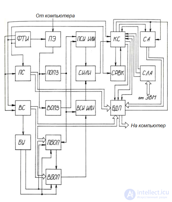
Fig. 2.30. Block diagram of a BSD that reads contour images
Fig. 2.30 shows a block diagram of a contour BSD that reads one TV-image frame in 0.02 s. The BSD contains the following units:
TIS - TV-image sensor;
TE - threshold element;
FOS - first one-shot with re-triggering;
SOS - second one-shot with re-triggering;
FXOR - first EXCLUSIVE-OR circuit;
SXOR - second EXCLUSIVE-OR circuit;
FRAB - first random-access memory block;
ORC - OR circuit;
CC - command circuit;
SRAB - second random-access memory block;
FC - first counter;
FSEC - frame sample enable circuit;
SC - second counter;
CU - control unit;
TDMB - two-dimensional memory block;
AC - addressing circuit;
ALC - address logic circuit.
The device operates in the following modes, set by the CC:
a) AC reset; b) TDMB erase; c) writing information (about the object image contours) into the TDMB; d) reading from the TDMB.
In reset mode the BSD's counters AC are reset to their initial state. In write mode the device operates synchronously with the TIS. The video-signal threshold level (the binarization level) is set by the computer. The FOS and SOS extend each pulse of the burst such that the pulse trains at the outputs of the FOS and SOS turn out to be shifted by the duration of one pulse in the burst. After this, on the output
of the FXOR a signal is formed characterizing the vertical boundaries of the object images. Writing signals into the FRAB and reading signals from the SRAB are performed synchronously with the informational part of the line, while reading information from the FRAB and writing information into the SRAB are performed during the period when there is no information (signal) on the line. Thus, in read mode from the SRAB, the information at its output is delayed by the duration of one line. As a result of the operation of the SXOR, the non-matching parts of the signal realizations on two adjacent lines are extracted, which
results in the formation of the horizontal parts of the object's contours. Thus, at the output of the ORC we obtain a signal characterizing
the contours of the object images.
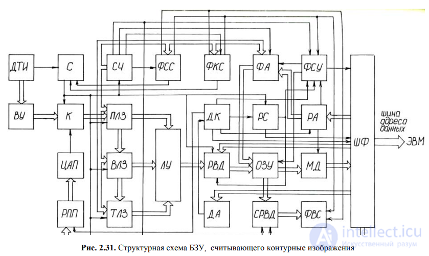
Fig. 2.31. Block diagram of a BSD that reads contour images
This information is written via the FSEC and CC into the TDMB. The state of the CC is set via the ALC from the microcomputer. Information is sampled from
the TDMB after the AC is reset to its initial state.
The described BSD differs from known ones in that all the information about the object contours in a TV image is read in a single frame.
Further development of this BSD is a device that allows reading several frames of an image.
The main drawback of the BSDs described above, namely the device's inability to detect image-element boundaries that are oriented horizontally along the line, is eliminated by a BSD whose block diagram is shown in Fig. 2.31.
The BSD performs the following functions in parallel: input of a binary image from the TV camera in a 256×256-element format, local
filtering of the image with a 3×3-element window, extraction of image contours, and output of the binary image to a monitor screen in a
256×256-element format.
The BSD contains the following units: TIS - TV-image sensor; VA - video amplifier; C - comparator; SG - sync generator; Ctr - counter;
DAC - digital-to-analog converter; FDL, SDL, TDL - first, second, and third delay lines; TSR - threshold switching register; LU - logic unit; LSPF - line sync-pulse former; FSPF - frame sync-pulse former; CD - command decoder; AD - address decoder; SR - status register; AR - address register; DIR - data input register; SDIR - shift data input register; RAM - random access memory; AF - address former; CSF - control-signal former; DM - data multiplexer; VSF -
video-signal former; BF - bus former.
The BSD works with a standard video signal coming from the television camera (TIS) through the VA to the C. Frame and line sync pulses are fed to the sync generator, which together with the Ctr provides the operation of the BSD. The operating principle of the filtering "window" used in the BSD is based, first, on organizing a 3×3-element decomposition matrix of the image; second, on analysis (comparing the brightness value of the "window" element with a threshold value); and third, on eliminating ("zeroing") non-informative image elements. For this purpose, three DLs are included in the BSD. To create the 3 × 3 matrix (3 columns of 3 rows), the scan signal must be stored (delayed) in the first DL for 3 decomposition elements, and in the second and third DLs for a time equal to the duration of one scan line of the decomposition matrix
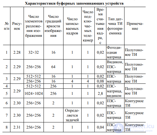
Table 2.8 Characteristics of buffer storage devices
Next, using the LU, which uses signals from all the DLs, the brightness value of the filtering
"window" element is compared with the threshold value, and non-informative image elements are zeroed out. The signal formed in this way, characterizing the contour of the images, can be written via the DIR into the RAM; this same signal can also be written into the computer's RAM and output to a monitoring display. In the latter case, the video signal is fed from the RAM to the SDIR, which converts the parallel code into serial form, and then to the VSF, which supplies the informational signal to the monitor. To create the raster on the monitor screen, sync pulses are formed using the LSPF and FSPF.
Their operation depends entirely on the state of the Ctr. The BF serves as the former of the input/output information signals and control signals.
The BSD provides the ability for the RAM to work both with the computer and autonomously. Switching between operating modes is carried out by the AF, which is controlled by the CSF. This unit also controls the RAM.
The CSF can operate either in automatic mode (depending on the state of the synchronizer) or on commands from the computer. This purpose is served by the CD, which also controls the AR, TSR, SR, and CSF.
The characteristics of the BSDs described above are given in Table 2.8.
Other types of memory are also used in robotics

Comments