
Lecture
Indoor positioning system (IPS) — a local system for determining location inside buildings and enclosed structures, where satellite navigation is practically unavailable.
Navigation (from Latin navigatio, from Latin navigo — «I sail on a ship»):
For many centuries, the term navigation meant the set of meanings listed above. In the 20th century, with the development of science and technology and the appearance of aircraft and spacecraft — new objects of navigation — new meanings of the term emerged. Now, in a general sense, navigation is the process of controlling some object (having its own means of movement) within a defined space of movement. It consists of two main parts:
Geolocation (geolocation) — determining the real geographic location of an electronic device, for example a radio transmitter, a cell phone, or a computer connected to the Internet. The word «geolocation» can refer both to the process of determining the location of such an object and to the location itself, established in this way. Geolocation purposes often use one positioning system or another, and it is often more important to determine the location in a form easily understood by a person (for example, a postal address) than to obtain precise geographic coordinates.
The word geolocation (geolocation) can also denote simply the geographic coordinates (latitude and longitude) of a given place on Earth (this definition of the term is given in the ISO/IEC 19762-5:2008 standard).
The term «geolocation» is also applicable to tracking animal migration (English)Russian. and to environmental monitoring using devices attached to animals' bodies, including implanted identification transponders and data loggers.
Buildings and structures create positioning difficulties for the following reasons:
On the other hand, indoor positioning and navigation can be simplified thanks to:
Indoor positioning system( IPS ) is a network of devices used to locate people or objects where GPS and other satellite technologies lack sufficient accuracy or are not fully available, for example inside multi-story buildings, airports, malls, parking garages, and underground locations.
A large number of different methods and devices are used to determine location indoors, ranging from already-deployed repurposed devices such as smartphones, Wi-Fi and Bluetooth antennas, digital cameras, and watches; to purpose-built installations with relays and beacons strategically placed within a given space. IPS networks use light, radio waves, magnetic fields, acoustic signals, and behavioral analytics. IPS can achieve positioning accuracy of 2 cm, comparable to RTK-enabled GNSS receivers, which can achieve 2 cm accuracy outdoors. IPS uses various technologies, including distance measurement to the nearest anchor nodes (nodes with known fixed positions, such as WiFi/LiFi access points, Bluetooth beacons, or ultra-wideband beacons), magnetic positioning, and dead reckoning. They either actively determine the location of mobile devices and tags, or provide location or environmental awareness for devices. The localized nature of IPS has led to fragmentation in design, with systems using a variety of optical, radio, or even acoustic technologies.
IPS has broad applications in the commercial, military, retail, and commodity industries. There are several commercial systems on the market, but there are no standards for an IPS system. Instead, each installation is adapted to the spatial dimensions, construction materials, accuracy requirements, and budget constraints.
For smoothing to compensate for stochastic (unpredictable) errors, there must be a reliable method for significantly reducing the error budget. A system can incorporate information from other systems to resolve physical ambiguity and provide error compensation. Detecting device orientation (often called compass heading to distinguish it from a smartphone's vertical orientation) can be achieved either by detecting landmarks within images captured in real time, or through trilateration with beacons. There are also technologies for detecting magnetometric information inside buildings or locations with steel structures, or in iron-ore mines.
The following technologies, which differ in their physical principle and the measurement accuracy achieved, can be used for indoor positioning:
Due to signal attenuation caused by construction materials, the Global Positioning System (GPS) loses significant power indoors, which affects the required coverage of receivers by at least four satellites. In addition, multiple reflections from surfaces cause multipath propagation, leading to uncontrolled errors. These same effects degrade all known solutions for indoor positioning that use electromagnetic waves from indoor transmitters to indoor receivers. A combination of physical and mathematical methods is applied to solve these problems. A promising direction for correcting radio-frequency positioning errors has opened up through the use of alternative sources of navigational information, such as an inertial measurement unit (IMU) and a monocular camera. Simultaneous localization and mapping (SLAM) and WiFi SLAM. Integrating data from various navigation systems with different physical principles can improve the accuracy and reliability of the overall solution.
The US Global Positioning System (GPS) and other similar global navigation satellite systems (GNSS) are generally not suitable for use indoors, since microwaves are attenuated and scattered by roofs, walls, and other objects. However, to make positioning signals ubiquitous, integration between GPS and indoor positioning can be performed.
GNSS receivers are currently becoming more and more sensitive due to the increasing computing power of microchips. High-sensitivity GNSS receivers can pick up satellite signals in most indoor locations, and attempts to determine three-dimensional position indoors have been successful. [26] In addition to increasing receiver sensitivity, A-GPS technology is used, in which the almanac and other information are transmitted via a mobile phone.
However, even though adequate coverage for the four satellites needed for receiver detection is not achieved in all current designs (2008–11) for indoor operation, GPS emulation has been successfully deployed in the Stockholm subway. [27] Solutions extending GPS coverage have been able to provide zonal indoor positioning available with standard GPS chipsets, such as those used in smartphones. [27]
Although most modern IPS are capable of determining an object's location, they are so coarse that they cannot be used to determine an object's orientation or heading.
One method of achieving sufficient operational usability is « tracking ». A given sequence of locations forms a trajectory from the first to the most recent actual location. Statistical methods then serve to smooth the locations determined along the track, taking into account the object's physical ability to move. This smoothing must be applied both when the target is moving and for a stationary target, in order to compensate for erroneous measurements. Otherwise, a single location, or even the followed trajectory, would form a wandering sequence of jumps.
In most applications there is more than one target. Consequently, an IPS must serve to properly identify each observed target and must be able to separate and distinguish targets individually within a group. An IPS must be able to identify the tracked objects despite "uninteresting" neighbors. Depending on the design, either the sensor network must know which tag it received information from, or the location device must be able to identify targets directly.
Any wireless technology can be used to determine location. Many different systems take advantage of existing wireless infrastructure for indoor positioning. There are three main system topology options for configuring hardware and software: network-based, terminal-based, and terminal-assisted. Positioning accuracy can be improved through wireless infrastructure hardware and installations.
A Wi-Fi positioning system (WPS) is used where GPS is inadequate. The localization technique used to determine location via wireless access points is based on measuring the intensity of the received signal ( received signal strength in English, RSS) and the «fingerprinting» method. To improve the accuracy of fingerprinting methods, statistical post-processing methods (such as Gaussian process theory) can be applied to convert a discrete set of «fingerprints» into a continuous RSSI distribution for each access point across the entire location. Typical parameters useful for geolocating a Wi-Fi access point or wireless access point include the SSID and MAC address of the access point. Accuracy depends on the number of positions entered into the database. Possible signal fluctuations that may occur can increase the number of errors and inaccuracies along the user's path.
Bluetooth was originally concerned with proximity rather than precise location. Bluetooth was not designed for anchored location determination like GPS; however, it is known as a solution for geofences or micro-fences, making it a solution for indoor proximity rather than a solution for indoor positioning.
Micromapping and indoor mapping have been associated with Bluetooth and, based on Bluetooth LE, iBeacon was promoted by Apple Inc. . A large-scale indoor positioning system based on iBeacons has been implemented and is applied in practice.
Bluetooth speaker location and home networks can be used for broad familiarization.
A simple concept of location indexing and presence reporting for tagged objects uses only known sensor identification. [11] This generally applies to passive radio-frequency identification (RFID) / NFC systems, which do not report the signal level and varying distances of individual tags or a large number of tags, and do not update any previously known location coordinates of the sensor or the current location of any tags. The functioning of such approaches requires some kind of narrow choke point to prevent going out of range.
Instead of measuring over a long distance, a dense network of short-range receivers can be arranged, for example in the form of a grid, to provide savings across the entire observed space. Due to the short range, a tagged object will only be identified by a few nearby network receivers. An identified tag must be within reach of the identifying reader, which allows the tag's location to be determined approximately. Advanced systems combine visual coverage with a camera grid with wireless network coverage for hard-to-reach places.
Most systems use continuous physical measurements (for example, only angle and distance, or distance alone) together with identification data in a single combined signal. The reach of these sensors typically spans an entire floor, corridor, or individual room. Short-range solutions are implemented with multiple sensors and overlapping ranges.
Angle of arrival (AoA) is the angle at which a signal reaches the receiver. AoA is usually determined by measuring the time difference of arrival (TDOA) between multiple antennas in a sensor array. In other receivers it is determined by an array of highly directional sensors - the angle can be determined by which sensor received the signal. AoA is typically used together with triangulation and a known baseline to determine location relative to two anchor transmitters.
Time of arrival (ToA, also time of flight) is the time required for a signal to propagate from the transmitter to the receiver. Since the signal propagation speed is constant and known (disregarding differences between media), the signal travel time can be used to directly calculate distance. Multiple measurements can be combined with trilateration and multilateration to find the location. This method is used in GPS and ultra-wideband systems. Systems using ToA usually require a complex synchronization mechanism to maintain a reliable time source for the sensors (although this can be avoided in carefully designed systems by using repeaters to establish a link [12] ).
The accuracy of TOA-based methods often suffers under conditions of severe multipath propagation in indoor localization, caused by the reflection and diffraction of the radio-frequency signal from objects (for example, interior walls, doors, or furniture) in the environment. However, the effect of multipath propagation can be reduced by applying methods based on temporal or spatial sparsity.
Received signal strength indication (RSSI) is a measurement of the power level received by the sensor. Since radio waves propagate according to the inverse-square law, distance can be approximately determined (typically to within 1.5 meters under ideal conditions and 2 to 4 meters under standard conditions ) based on the ratio between the transmitted and received signal levels (transmit power being a constant value depending on the equipment used), as long as no other errors lead to erroneous results. Indoors is not free space, so accuracy is significantly affected by reflection and absorption from walls. Non-stationary objects such as doors, furniture, and people can present an even bigger problem, since they can affect signal power in a dynamic and unpredictable way.
Many systems use extended Wi-Fi infrastructure to provide location information. None of these systems is designed to work correctly with just any infrastructure as-is. Unfortunately, Wi-Fi signal level measurements are very noisy, so research is currently underway aimed at creating more accurate systems using statistics to filter out inaccurate input data. Wi-Fi positioning systems are sometimes used outdoors as a supplement to GPS on mobile devices, where only a few stray reflections interfere with the results.
Non-radio technologies can be used to determine location without using existing wireless infrastructure. This can provide increased accuracy at the cost of expensive equipment and installations.
Magnetic positioning can offer pedestrians with smartphones an accuracy of 1–2 meters indoors with a 90% confidence level, without using additional wireless infrastructure for location determination. Magnetic positioning relies on the iron within buildings, which creates local variations in the Earth's magnetic field. Unoptimized compass chips inside smartphones can detect and record these magnetic variations to map indoor locations.
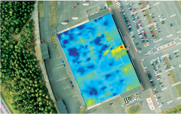
Among those familiar with magnetic positioning, there is a relatively common belief that
distortions caused by construction materials such as steel and concrete will reduce accuracy.
However, the opposite is true; IndoorAtlas claims that it is precisely this magnetic-field distortion
that makes it possible to position people indoors.
Comparison of technologies: WiFi, BLE, and Magnetic positioning
| Technology | Accuracy | Infrastructure | Setup / Maintenance costs | Power supply | Development environment |
| Magnetic positioning |
6 feet | API / minimal | Crowdsourced | none | iOS/Android |
| WiFi | 20-300 feet | Hardware/ Software | Remapping - Fingerprinting |
Electricity/ Battery |
iOS/Android |
| BLE | 6 -100 feet | Hardware/ Software | Device Control |
Electricity/ Battery |
iOS/Android |
|
Dead reckoning (or positional reckoning) Pedestrian dead reckoning (PDR) (pedestrian dead reckoning) |
Software/Cloud | Crowdsourcing | no | iOS/Android | |
| Other (cameras, LED, sound) | variable | Hardware/ Software | Device Control |
iOS/Android |
Pedestrian dead reckoning and other approaches to determining pedestrian location employ an inertial measurement unit carried by the pedestrian, either by indirectly measuring steps (step counting) or through a foot-mounted approach, sometimes referencing maps or other auxiliary sensors to limit the natural sensor drift that occurs during inertial navigation. MEMS inertial sensors suffer from internal noise that over time leads to a cubic growth in position error. To reduce the growth of errors in such devices, an approach based on Kalman filtering is often used. However, to make it capable of building a map, the SLAM[54] algorithm framework is used.
Inertial measurements generally cover differentials of motion, so location is determined by integration, and integration constants are therefore required to obtain results. The actual location estimate can be found as the maximum of a two-dimensional probability distribution, which is recalculated at each step taking into account the noise model of all sensors involved and the constraints created by walls and furniture. Based on users' movements and walking behavior, an IPS can estimate user location using machine learning algorithms.
Inertial navigation — a navigation method (determining the coordinates and motion parameters of various objects — ships, aircraft, rockets, etc.) and controlling their motion, based on the inertial properties of bodies, which is autonomous, i.e. requiring no external reference points or signals coming from outside. Non-autonomous methods of solving navigation problems are based on the use of external reference points or signals (for example, stars, beacons, radio signals, etc.). These methods are, in principle, fairly simple, but in a number of cases cannot be implemented due to lack of visibility or the presence of interference with radio signals, etc. The need to create autonomous navigation systems was the reason for the emergence of inertial navigation.
The essence of inertial navigation lies in determining the acceleration of an object and its angular velocities using instruments and devices mounted on the moving object, and from this data — the location (coordinates) of the object, its heading, speed, distance traveled, etc., as well as determining the parameters necessary for stabilizing the object and automatically controlling its motion. This is accomplished using :
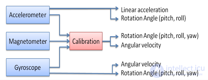
The advantages of inertial navigation methods lie in their autonomy, noise immunity, and the possibility of fully automating all navigation processes. Thanks to this, inertial navigation methods are becoming increasingly widely used in solving navigation problems for surface, underwater, and airborne vessels, spacecraft, and other moving objects.
Inertial navigation is also used for military purposes: in cruise missiles and UAVs, in the event of enemy electronic countermeasures. As soon as the navigation system of a cruise missile or UAV detects the effects of enemy electronic warfare systems, jamming, or distortion of the GPS signal, it remembers the last coordinates and switches to the inertial navigation system[
A visual positioning system can determine the location of a mobile device equipped with a camera by decoding location coordinates from visual markers. In such a system, markers are placed at specific locations throughout the facility; each marker encodes the coordinates of that location: latitude, longitude, and height above the floor. Measuring the viewing angle from the device to the marker allows the device to estimate its own location coordinates relative to the marker. The coordinates include latitude, longitude, altitude, and height above the floor.
ArUco markers are a popular technology for positioning robotic systems using computer vision.
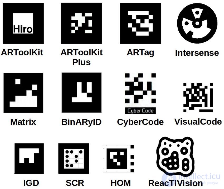
different types of markers
A series of consecutive images from the device's camera can build an image database suitable for estimating location at the site in question. Once the database has been built, a mobile device moving around the facility can take pictures that can be interpolated against the facility's database to obtain location coordinates. These coordinates can be used together with other location-determination methods to improve accuracy. Note that this can be a special case of sensor fusion, in which the camera plays the role of yet another sensor.
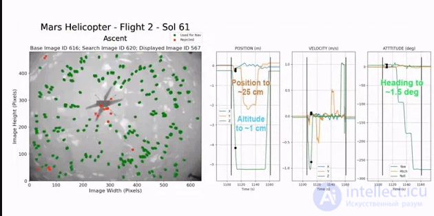
Feature-point tracking, as used by the Ingenuity helicopter
After sensor data has been collected, the IPS attempts to determine the location from which the received transmission most likely originated. Data from a single sensor is generally ambiguous and must be resolved using a range of statistical procedures to combine multiple sensor input streams.
One way to determine location is to match data from an unknown location against a large set of known locations using an algorithm such as k-nearest neighbor. This method requires a comprehensive on-site survey and will be inaccurate under any significant changes in the environment (due to moving people or moving objects).
Location is calculated mathematically by approximating signal propagation and determining angles and/or distance. Inverse trigonometry is then used to determine location:
Advanced systems combine more accurate physical models with statistical procedures:
Indoor positioning systems are used in a large number of applications:
The main consumer benefit of indoor positioning is the spread of location-aware mobile computing indoors. As mobile devices become ubiquitous, context awareness in applications is becoming a priority for developers. However, most applications currently rely on GPS and perform poorly indoors. Indoor applications include:
etc.
Visual odometry is a method for estimating the position and orientation of a robot or other device by analyzing a sequence of images captured by a camera (or cameras) mounted on it.
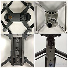
Visual odometry methods are used, for example, in computer optical mice. They are also used in quadcopters and on the Mars Exploration Rover rovers.
In robotics and computer vision, visual odometry is the process of determining the position and orientation of a robot by analyzing associated camera images. It has been used in a wide range of robotic applications, for example on the Mars Exploration Rover rovers.
In navigation, odometry is usually associated with the use of drive motion data (for example, from rotation sensors) to estimate a change in position in space. This method has its drawbacks, due to slippage and inaccuracies when moving over uneven surfaces, and is also inapplicable to robots with non-standard locomotion methods, for example, walking robots.
Visual odometry is suitable for precise navigation using any type of locomotion on a solid surface.
Most existing approaches to visual odometry are based on the following stages.
The direct visual odometry technique performs the above operations directly on the sensor.
Visual odometry estimates planar rotational displacements between images using phase correlation instead of feature extraction.

Comments