
Lecture
Wheel Encoder (scroll wheel encoder) is a miniature device inside a computer mouse that converts the rotation of the scroll wheel into digital pulses. These pulses let the operating system determine the direction and speed of wheel rotation, providing vertical or horizontal scrolling in the interface.
A scroll wheel is a wheel used for scrolling . The term usually refers to such wheels used on computer mice (where they are also simply called the mouse wheel ). It is often made of hard plastic with a rubber surface and rotates around an internal rotary encoder . It is normally located between the left and right mouse buttons and perpendicular to the surface of the mouse. Sometimes the wheel can be pressed to the left and to the right, which effectively amounts to two additional macro buttons.
The scroll wheel sits horizontally between the mouse buttons and is generally used for vertical scrolling, with rotation of the wheel from bottom to top being called scrolling "up" or "forward", and the reverse motion, that is, rotation of the wheel from top to bottom, being called scrolling "down" or "back".
In a graphical user interface, the "up" motion moves the window content down (and the scroll bar thumb , if there is one, up), and vice versa. In other configurations (sometimes called "natural scrolling") the effect is reversed.
On most mice the scroll wheel can often be used as a third, middle mouse button by pressing it , and this is called the scroll button .
The scroll wheels of some mice can scroll horizontally when tilted to the left or right , or an additional wheel on a perpendicular axis may be placed elsewhere on the mouse.
The wheel is often, though not always, built with detents so that it turns in discrete steps rather than continuously like an analog axis, making it easier for the operator to intuitively sense how far he is scrolling.
Scroll wheels are widespread on modern computer mice and have become an integral part of the hardware interface . Mice without a wheel are, however, still available.
Some user interfaces, such as Cinnamon (desktop environment) , allow it to be used to adjust brightness and volume by pointing at the corresponding icon in the taskbar while scrolling.
The mouse wheel is mechanically coupled to a rotary encoder.
When the user turns the wheel, the encoder converts its motion into a series of electrical pulses, which the mouse microcontroller interprets as "scroll up" or "scroll down" commands.
In practice, two main types of encoders are used:
Classification by the height between the axis of rotation and the bottom
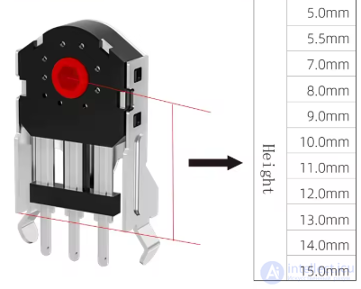
Classification by the physical operating principle
The most common and cheapest type, used in classic mice.
Inside the wheel there is a slotted metal disc and two contact springs.
As the disc rotates, it makes and breaks the contacts, producing a series of pulses with a small delay between the channels (A and B).
The controller determines the direction of rotation from the phase shift between signals A and B.
Advantages: simplicity, low cost.
Disadvantages: contact wear, "noise" (bounce), limited service life.
Characteristics of mechanical encoders:
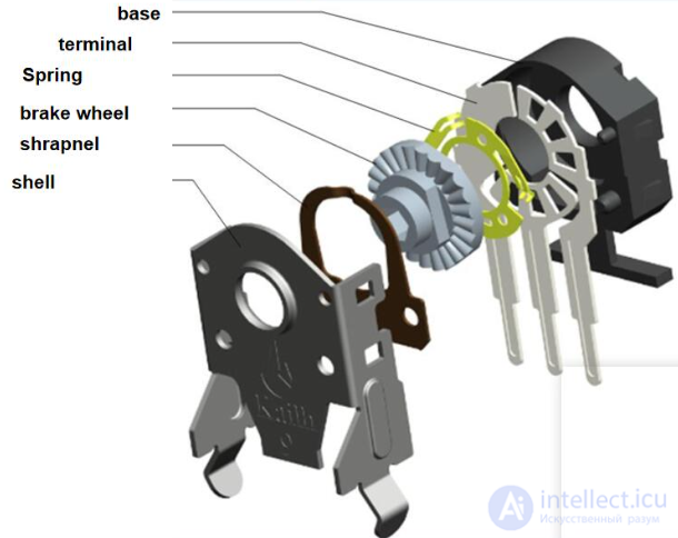
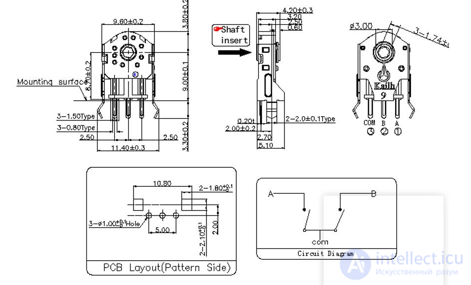
Used in more expensive or modern models.
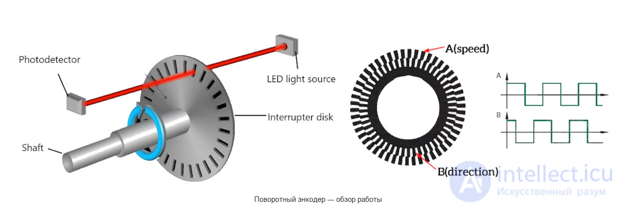
Instead of contacts, an infrared LED and photodetectors are used.
A transparent slotted disc is fixed on the wheel axis.
As it rotates, the light beam is periodically interrupted, forming pulses similar to those of the mechanical version.
Advantages: durability, high accuracy, no mechanical wear.
Disadvantages: higher cost, sensitivity to dust.
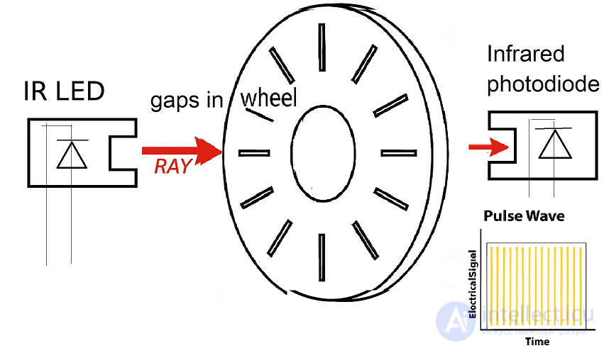
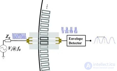
The optical incremental rotary encoder is the most popular position feedback device in modern servo systems. Optical encoders attach an opaque mask to the motor rotor. As the rotor position changes, the shape of the light spot passing through the mask changes. The encoder generates electronic pulses when the light intensity changes within a set value. The optical mask is designed to create a cyclic pattern of change that repeats hundreds or thousands of times per motor revolution. As a result, an incremental encoder typically delivers from 250 to 5000 counts of position information per motor revolution. These pulses are generated in proportion to the distance traveled by the encoder. The pulses are counted by the control system to determine the distance traveled by the encoder rotor. The A and B phases of the encoder are the output signals of incremental-type rotary encoders. The phase A signal gives the shaft rotation angle before and after the operation, while phase B is the output signal for the direction of shaft rotation.
This 400 PPR AB two-phase rotary encoder is an industrial-grade optical encoder with quadrature outputs for incremental counting. It is equipped with a 6 mm diameter solid shaft for coupling to a motor shaft. This encoder delivers 400 pulses per revolution (PPR) between phases A and B. The encoder comes with a 1.5 meter cable for connection.
Features:
Applications: widely used in elevators, servo motors, paper manufacturing, the packaging industry, the textile industry, printing, computer mice and other sectors.
Specification:
Used less often, in premium mice (for example, the Logitech MX Master).
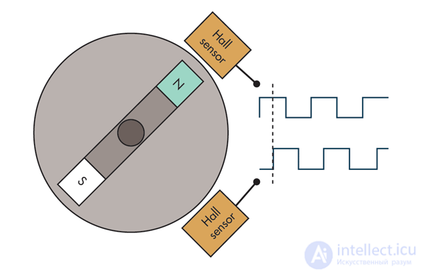
A permanent magnet is mounted on the wheel axis, with a Hall sensor next to it.
The sensor reads the change in the magnetic field during rotation and generates a digital signal.
Advantages: non-contact operation, reliability, high accuracy.
Disadvantages: complexity and cost.
The encoder has two output channels (A and B), shifted in phase by 90°.
If signal A leads B, scrolling goes forward (up).
If B leads A, scrolling goes backward (down).
This method is called quadrature encoding, and the system is called a quadrature encoder.
Rotary encoders convert rotary motion or angular position into analog or digital signals for use in measurement or control systems. They can be classified in various ways, primarily by the type of output signal: absolute or incremental.
An incremental signal consists of two phase-shifted square-wave signals. The phase shift is needed to determine the direction of rotation. An absolute signal consists of discrete coded binary values and can have a width of 4 to 16 bits.
In practical use, absolute encoders are required if a given setting has to be recognized and accessed after the system is switched off. In all other cases an incremental encoder can be used. Encoders can also be classified by the sensing technology they use, which may rely on mechanical contacts or, more commonly these days, on non-contact optical or magnetic sensors.
The range of encoder applications is extremely broad, covering consumer, automotive, industrial and medical equipment. In essence, encoders perform one of two functions: they provide a human-machine interface (HMI) or a machine-machine interface (MMI).
In HMI applications, encoders are often found in control panels, where they are usually regarded as a digital version of a potentiometer. A less obvious but increasingly popular application is in control lever or pedal assemblies, replacing mechanical cables or linkages, for example in automotive throttle control systems.
In MMI applications, encoders are invariably used as part of closed-loop control systems, where they count spindle revolutions or monitor speed. Many systems are fitted with encoders that close the loop on an HMI input. Thus, in automotive throttle control systems, a second encoder probably measures engine speed (rpm) to control fuel injection and engine timing in order to achieve the desired acceleration. Or it may measure the rudder position on a vessel to confirm that it matches the helm setting.
How do they work?
Magnetic encoders use a combination of permanent magnets and magnetic sensors to determine displacement and position. A typical design uses magnets placed around the edge of a rotor disc mounted on the shaft and positioned so that the sensor registers changes in the magnetic field as the alternating magnet poles pass by it.
The simplest configuration includes a single magnet, with its north and south poles located at opposite edges of the rotor, and a single sensor. Such an arrangement delivers a sinusoidal signal at a frequency equal to the shaft rotation speed.
With a second sensor mounted at 90° to the first, and therefore generating a cosinusoidal signal, it becomes possible not only to determine the direction of rotation but also to interpolate the absolute shaft position from the sine and cosine signals (Fig. 1). In incremental encoders, the sinusoidal sensor outputs are converted into square waves, so the resulting quadrature signals can only be encoded into one of four possible angular positions. Higher resolution is achieved by increasing the number of magnetic poles around the rotor and using more sensors. For example, 1024 positions (or 10-bit resolution) can be obtained with four sensors and 128 poles.
1. A magnetic rotary encoder consists of two poles and two sensors. The second sensor makes it possible not only to determine the direction of rotation, but also to interpolate the absolute position of the shaft.
Optical encoders use a rotor disc of plastic or glass carrying a pattern of transparent and opaque areas that can be detected as the disc turns between a light source and a photodetector. As with the magnetic encoder, the simplest configuration can use just one sensor, with one half of the disc transparent and the other opaque. For higher resolution, however, the disc is usually divided into a larger number of segments (often in the form of concentric rings) read by two or more sensors.
Here again, the correct arrangement of the rotor pattern and the sensor positions can provide the quadrature output signal characteristic of incremental encoders. To minimize the number of pins, data from an absolute encoder is usually output serially. And although most commercial encoders are rotary, the same measurement and encoding principles can also be applied to linear encoders.
The pulses from the encoder go to the mouse microcontroller, which:
Reads the frequency and direction of rotation.
Converts them into USB HID protocol commands.
Sends the signal to the computer as Scroll Up / Scroll Down events.
From the user's point of view, the encoder technology (magnetic or optical) matters only insofar as it determines the performance that can be achieved. In particular, when used as part of a man-machine interface (MMI), the encoder is subjected to mechanical loads and must also work when rotated quickly.
Consequently, once it has been decided whether incremental or absolute encoding is required, the key selection criteria are the rotational speed, measured in rpm, and the angular resolution, expressed either as the number of positions per revolution or as an equivalent number of bits. Magnetic rotary encoders
Of course, if the intended application involves prolonged operation of the encoder at high speeds, it makes sense to consider service life, that is, to choose an encoder with suitable high-performance ball bearings. Beyond that, the usual criteria of quality, reliability and price should be taken into account.
Over time the scroll wheel can start behaving erratically: skipped steps, double scrolling, "chatter", or no response at all.
The causes depend on the type of encoder — mechanical, optical or magnetic.
Scrolling "jumps" — up and down uncontrollably.
The wheel does not respond to every step.
Scrolling works in one direction only.
An unusual rustling or crackling can be heard inside.
The wheel turns too easily or, conversely, too stiffly.
Cause: dust, dirt, wear of the metal tracks, moisture.
Symptoms: "floating" scrolling, random pulses.
Fix:
Disassemble the mouse and the encoder housing (carefully bending back the latches).
Clean the disc and the contacts with a cotton swab moistened with isopropyl alcohol (IPA).
If wear is severe, replace the encoder completely (compatible models: ALPS EC10E, TTC, Bourns and others).
Cause: years of use (millions of scroll steps).
Symptoms: the wheel responds with a delay, "drops out" in one position.
Fix:
The contact leaves can be bent back temporarily with tweezers.
But the long-term solution is to replace the encoder.
Cause: dust in the slots of the disc, or a weakly glowing IR LED.
Symptoms: unstable scrolling.
Fix:
Clean the disc and the optical path with a soft brush or alcohol.
Check for the LED signal using a smartphone camera (a faint violet light is visible).
If necessary, replace the LED or the module itself.
Cause: mechanical damage from a drop or from pressing too hard.
Symptoms: the wheel wobbles or does not turn the encoder.
Fix:
Check whether the plastic bushing or the axle is broken.
If necessary, glue it with epoxy resin or fit a wheel from a similar model.
Cause: a botched repair, corrosion, worn solder joints.
Symptoms: no response to rotation at all.
Fix:
Use a multimeter to check for a signal on the encoder pins (channels A and B).
Resolder the contacts and restore the tracks with thin wire.
A rare but possible cause.
If the encoder is working but scrolling is not, the microcontroller input may be damaged.
Fix:
Test the encoder separately with an oscilloscope.
If the microcontroller does not respond, replace the board or the whole mouse.
Do not use aggressive liquids for cleaning.
Avoid dust and humidity.
Clean the inside with compressed air once or twice a year.
At the first signs of chatter, clean and lubricate with a light silicone oil (mechanical models only).
lubricate with Litol grease or ordinary sewing-machine oil, but there is a risk of a short circuit and damage
Many manufacturers (Logitech, Razer, ASUS) are gradually moving to magnetic or optical encoders in order to get rid of the problems of chatter and wear.
In such systems the "clicky" feel of rotation is simulated in software, which improves the durability and accuracy of scrolling.
The first scroll wheel with an encoder appeared in 1995 in the Microsoft IntelliMouse.
The design of encoders has barely changed since then, but silent and inertial wheels have appeared, using software-adjustable resistance to rotation and a magnetic position sensor.
The mouse scroll wheel was invented many times over by different people who were unaware of each other's work.
Other mouse scrolling controls, as well as the use of a wheel for scrolling, predate the combination of wheel and mouse. The earliest known example of such a device is the Mighty Mouse prototype developed jointly by NTT (Japan) and ETH Zürich (Switzerland) in 1985 (Kunio Ono, Ken'ichi Fukaya and Jürg Nievergelt). On the side of the mouse was a thumb-operated combined analog button / switch for smooth scrolling.
At the ACM SIGCHI conference in 1989, Gina Danielle Venolia of Apple presented a prototype mouse with a horizontal wheel for scrolling or for navigating in and out: zooming, or along a third axis in three-dimensional space. Her 1992 patent application specifies two vertical wheels: to the left and to the right of the button(s).
In 1995 the Taiwanese company KYE Systems released the first commercial mouse with a scroll wheel. It was called the Genius EasyScroll and was also available under the name Mouse Systems ProAgio.
The scroll wheel became popular thanks to the Microsoft IntelliMouse in 1996, and mouse wheel support appeared in Microsoft Office 97. It was based on ideas that Eric Michelman had been developing since 1993 with the participation of Chris Graham.
Scroll wheels can also be found on PDAs and mobile phones, such as early Sony models, BlackBerry devices and the Nokia 7110, where they usually serve for menu navigation. They have also appeared on keyboards, especially Logitech and Microsoft models, usually placed to the left of the Caps Lock key
Instead of a scroll wheel, some mice (and other devices) use an alternative but similar component.
Laptops are often fitted with a touchpad programd to recognize pointer gestures that emulate scroll wheel scrolling (either by dedicating an edge of the pad to scrolling, or by activating scrolling with a multi-touch gesture), or that emulate scroll wheel button presses (pressing the left and right buttons together to activate omnidirectional scrolling). Many Linux distributions offer a touchpad scrolling method in which the user first activates scrolling mode by tapping a corner of the pad and then moves a finger in a circle around its center; releasing the touchpad returns to the default mouse mode.
In mice, the alternatives are scroll balls (similar to trackballs, such as the one on Apple's Mighty Mouse and some serial or PS/2 mice that combine horizontal and vertical scrolling), pointing sticks, integrated touch surfaces (as on Apple's Magic Mouse) or optical sensors. Unusual examples include the joystick switch found on an early Saitek mouse and the central 4-way switch pad found on the Cherry Power Pad Mouse M-1000. Genius also offered a simpler NetMouse in the late 1990s, which had a two-position rocker switch instead of a wheel, marketed as the Magic Scroll Button. Kensington currently offers several trackball mouse models with a large "scroll ring" that surrounds the ball itself and is turned with several fingers rather than with the index finger alone, as on the scroll wheel of an ordinary mouse.
Some ThinkPad laptops allow the screen to be scrolled with the pointing stick while holding down a button above the touchpad.

Comments