
Lecture
A digital micromirror device, or DMD, is a micro-opto-electromechanical system (MOEMS) that forms the basis of Texas Instruments' (TI) patented Digital Light Processing (DLP) projection technology. The device is used in digital projectors and consists of an array of millions of microscopic mirrors that can be tilted individually many thousands of times per second, thereby forming the pixels of the projected image.
The technology dates back to 1973, when Harvey C. Nathanson (the inventor of MEMS, around 1965) used millions of microscopically small moving mirrors to produce a video image similar to the one now used in digital projectors.
The project at Texas Instruments began with a deformable mirror device in 1977 that used micromechanical analog light modulators. The DMD was invented in 1987 by solid-state physicist and TI Fellow Emeritus Dr. Larry Hornbeck. The first analog DMD-based product was the TI DMD2000 airline ticket printer, which reached the market in 1990 and used a DMD instead of a laser scanner.
In DLP projectors the image is created by microscopically small mirrors laid out in an array on a semiconductor chip known as a digital micromirror device (DMD). These mirrors are so small that the DMD pixel pitch may be 5.4 µm or less. Each mirror represents one or more pixels in the projected image. The number of mirrors corresponds to the resolution of the projected image (often half as many mirrors as the stated resolution, because of wobulation). Arrays of 800×600, 1024×768, 1280×720 and 1920×1080 (HDTV) are some common DMD sizes. These mirrors can be repositioned rapidly to reflect light either through the lens or onto a heat sink (called a light dump in Barco's terminology).
Switching the mirror rapidly between these two positions (essentially on and off) makes it possible to produce shades of gray, controlled by the ratio of on time to off time.
On the surface of a DMD chip there are several hundred thousand microscopic mirrors arranged in a rectangular array, which correspond to the pixels of the displayed image. The mirrors and their supporting mechanical structures are fabricated using surface micromachining. The mirrors can be rotated individually by ±10–12° into an on or off state. In the on state, light from the projector lamp is reflected into the lens, which makes the pixel appear bright on the screen. In the off state, the light is directed elsewhere (usually onto a heat sink), which makes the pixel appear dark. To produce shades of gray, the mirror is switched on and off very rapidly, and the ratio of on time to off time determines the resulting shade (binary pulse-width modulation). Modern DMD chips can reproduce up to 1024 shades of gray (10 bits). See the "Digital Light Processing" section for a discussion of how color images are created in DMD-based systems.
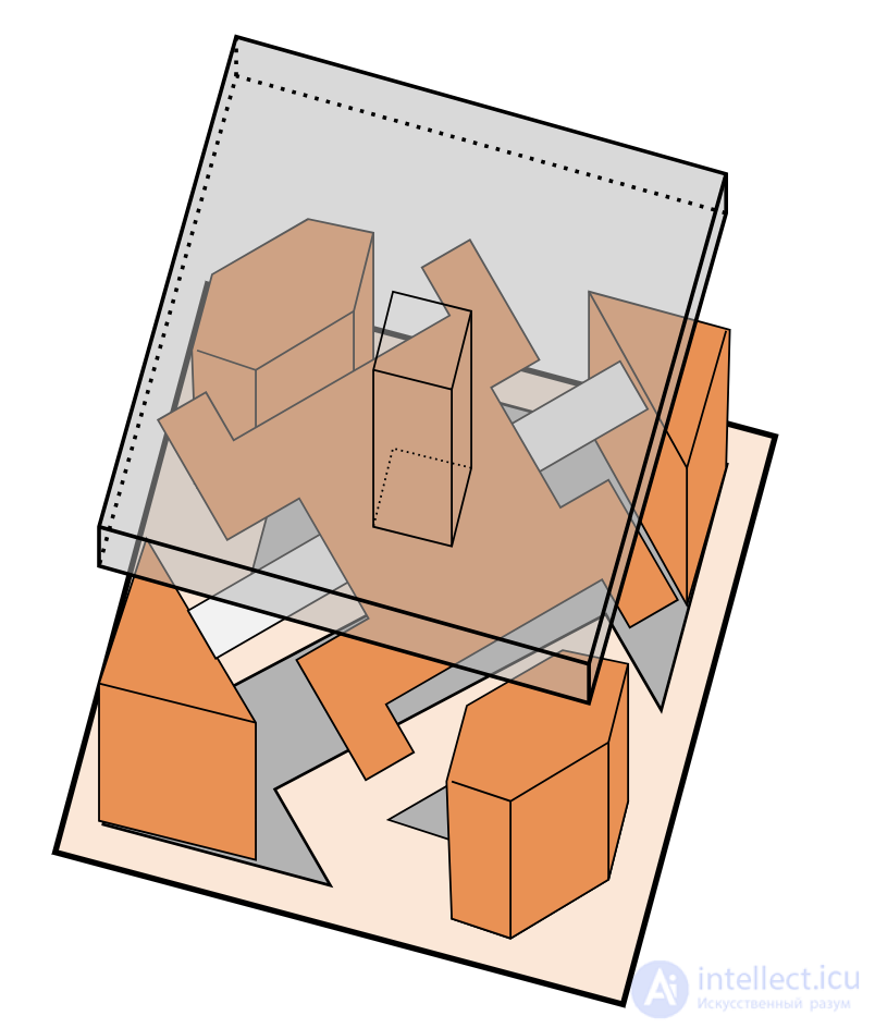
Diagram of a digital micromirror, showing the mirror mounted on a suspended yoke with a torsion spring running from lower left to upper right (light gray), together with the electrostatic pads of the memory cells located below (upper left and lower right).
The mirrors themselves are made of aluminum and are about 16 micrometers across. Each mirror is mounted on a yoke, which in turn is connected to two support posts by flexible torsion hinges. In this type of hinge the axis is fixed at both ends and twists in the middle. Because of the small scale, hinge fatigue is not a problem, and tests have shown that even 1 trillion (10¹²) operations cause no noticeable damage. Tests have also shown that the hinges cannot be damaged by ordinary shock and vibration, since these are absorbed by the DMD superstructure.
Two pairs of electrodes control the position of the mirror by electrostatic attraction. Each pair has one electrode on each side of the hinge, with one pair arranged to act on the yoke and the other directly on the mirror. In most cases equal bias charges are applied to both sides at once. Rather than flipping to a central position, as one might expect, this actually holds the mirror in its current position. This happens because the attractive force is greater on the side toward which the mirror is already tilted, since that side is closer to the electrodes.
To move the mirrors, the required state must first be loaded into the SRAM cell located beneath each pixel and also connected to the electrodes. Once the data has been loaded into all the SRAM cells, the bias voltage is removed, allowing the charges from the SRAM cells to prevail and move the mirror. When the bias voltage is restored, the mirror is again latched in the required position, and the next required movement can be loaded into the memory cell.
The bias system is used because it lowers the voltage levels needed to address the pixels, so that they can be driven directly from the SRAM cell, and also because the bias voltage can be removed simultaneously for the whole chip, so that every mirror moves at the same instant. The advantages of the latter are more accurate timing and a more cinematic moving image.
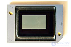
A damaged DMD chip, whose screen shows "white dots" as "white pixels".
The described failure mode of these devices is caused by internal contamination, usually from a loss of hermetic sealing that leads to corrosion of the mirror supports. A similar failure has been linked to an adhesive used between 2007 and 2013 which, under the influence of heat and light, breaks down and outgasses: this usually results in fogging of the glass and ultimately in white/black pixels. As a rule this cannot be repaired, but defective DMD chips can sometimes be used for less critical projects that do not require fast pattern changes, if the existing defective pixels can be incorporated into the projected image or otherwise accounted for, including 3D scanning.
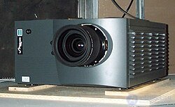
A Christie Mirage 5000 projector, a DLP model from 2001.
Digital Light Processing (DLP) technology is a chipset based on optical microelectromechanical technology that uses a digital micromirror device. It was originally developed in 1987 by Larry Hornbeck of Texas Instruments. Although the DLP device itself was invented by Texas Instruments, the first DLP-based projector was introduced by Digital Projection Ltd in 1997. Digital Projection and Texas Instruments were awarded an Emmy in 1998 for DLP projector technology.
DLP technology is used in DLP projection devices (standalone projection units, mainly for classrooms and businesses), DLP rear-projection televisions and digital displays. It was also used in about 85% of digital cinema projection systems around 2011, as well as in additive manufacturing as the light source in some printers that cure resins into solid 3D objects.
DLP technology has been used in a wide variety of display applications, from traditional static ones to interactive ones, and also in non-traditional embedded systems, including medical, security and industrial applications. More compact "pico" chipsets have been used in mobile devices, including cell phone accessories and projection displays built directly into phones.
There are two main methods of creating a color image in DLP projection systems: the methods used in single-chip DLP projectors, and the methods used in three-chip projectors. A third method, sequential illumination by three colored LEDs, is under development and is currently used in televisions made by Samsung.
 |
 |
 |
 |
 |
|||
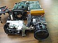
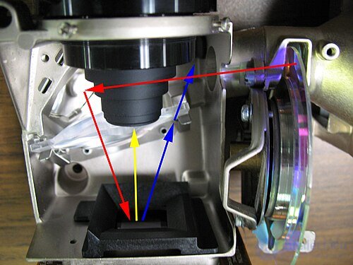
| Interior view of a single-chip DLP projector, showing the light path. Light from the lamp enters a reverse fisheye, passes through the rotating color wheel, crosses the space beneath the main lens, reflects off a front-surface mirror and is spread onto the DMD array (red arrows). From there the light either enters the lens (yellow) or is reflected off the top cover down into a light dump (blue arrows), absorbing the unwanted light. The top row shows the general components, close-ups of the 4-segment RGBW color wheel and of the diffuser/reflector plate on the top cover. | |||
In a single-DLP-chip projector, colors are produced either by placing a color wheel between a white lamp and the DLP chip, or by using separate light sources to produce the primary colors, for example LEDs or lasers. The color wheel is divided into several sectors: the additive primary colors red, green and blue, and in many cases white (clear) as well. In newer systems the white is replaced by the subtractive primary colors cyan, magenta and yellow. The use of subtractive colors is part of the new BrilliantColor color-processing system, which handles the additive colors together with the subtractive colors to create a wider range of possible color combinations on screen.
The DLP chip is synchronized with the rotation of the color wheel, so that the green component is displayed on the DMD when the green section of the color wheel is in front of the lamp. The same applies to the red, blue and other sections. The colors are thus displayed sequentially at a rate high enough for the observer to see a composite "full-color" image. In early models this was one revolution per frame. Most systems now run at ten times that frame rate.
The black level in a single-chip DLP projector depends on how the unused light is disposed of. If the unused light is scattered by reflecting and diffusing off the rough interior walls of the DMD array and lens compartment, that scattered light will be visible on the projection screen as a dim gray when the image is fully dark. Deeper blacks and higher contrast ratios are achieved by directing the unused light away from the HID array and lens compartment into a separate area for dissipation, and by shielding the light path from unwanted internal secondary reflections.
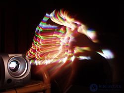
The rainbow effect seen in 1DLP projectors that use only a mechanical rotating wheel.
Single-chip DLP projectors that use a mechanical rotating color wheel can exhibit an anomaly known as the "rainbow effect". It is best described as brief flashes of perceived red, blue and green "shadows", most often seen when the projected content contains high-contrast areas of moving bright or white objects on a mostly dark or black background. Common examples are the scrolling credits at the end of many films, as well as animation with moving objects surrounded by a thick black outline. Brief visible color separation can also be noticeable when the viewer's gaze moves quickly across the projected image. Some people notice these rainbow artifacts often, while others may never see them.
This effect is caused by the way the eye tracks a moving object on the projected image. When an object on the screen moves, the eye follows it at a constant speed, but the projector displays each alternating color of the frame at the same location for the whole duration of that frame. So while the eye is moving, it sees the frame in one particular color (red, for example). Then, when the next color (green, for example) is displayed, even though it appears in the same place, overlapping the previous color, the eye has already moved on to the next target point of the object's frame. The eye therefore sees that particular color frame slightly displaced. The third color (blue, for example) is then displayed, and again the eye sees that color frame slightly displaced. The effect is perceived not only for a moving object but for the entire image. Multicolor LED and laser projectors based on single-chip systems are able to eliminate the color-wheel rotation effect and minimize the rainbow effect, because the pulse frequency of LEDs and lasers is not limited by physical motion. Three-chip DLP projectors operate without color wheels and therefore do not exhibit this rainbow artifact.
In a three-chip DLP projector, a prism is used to split the light from the lamp, and each primary color of light is then directed to its own DMD chip, after which the beams are recombined and output through a lens. Three-chip systems are used in high-end home theater projectors, large-venue projectors and the DLP Cinema projection systems used in digital movie theaters.
According to DLP.com, three-chip projectors used in movie theaters can reproduce 35 trillion colors. The human eye is thought to be able to distinguish about 16 million colors, which is theoretically achievable with a single-chip solution. However, such high color accuracy does not mean that three-chip DLP projectors are able to display the entire range of colors we can distinguish (this is fundamentally impossible for any system that creates colors by adding three fixed primary colors). By comparison, single-chip DLP projectors have the advantage of allowing any number of primary colors in a sufficiently fast color filter, which opens up the possibility of extending the color gamut.
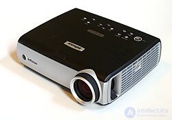
An InFocus IN34 projector, which uses DLP technology.
DLP technology does not depend on the light source and can therefore be used effectively with a variety of light sources. Historically, the main light source used in DLP display systems was a replaceable high-pressure xenon arc lamp unit (containing a quartz arc tube, a reflector, electrical connections and sometimes a quartz/glass shield), whereas most pico-category (ultra-small) DLP projectors use high-power LEDs or lasers as their illumination source. Since 2021, laser light sources have become very common in many professional projectors, for example in the Panasonic PT-RZ990.
Xenon arc lamps use a DC power supply that starts at a sufficiently high open-circuit voltage (5 to 20 kV, depending on the lamp) to strike an arc between the electrodes; once the arc is established, the voltage across the lamp drops to a set value (typically 20 to 50 volts), while the current rises to the level required to sustain the arc at optimum brightness. As the lamp ages, its efficiency decreases because of electrode wear, which results in less visible light and more heat being generated. The end of the lamp's service life is usually indicated by an LED on the unit or by a text warning on the screen, calling for replacement of the lamp unit.
Continuing to operate the lamp beyond its rated service life can lead to a further drop in efficiency, uneven light output, and eventually to the lamp heating up to the point where the power leads may melt at the terminals. Ultimately the required striking voltage will also rise to the point where ignition becomes impossible. Additional protective measures, such as a temperature sensor, may shut the projector down, but an overheated quartz arc tube can also crack or explode. Practically all lamp housings contain heat-resistant barriers (in addition to those on the lamp unit itself) to prevent white-hot quartz fragments from escaping the working area.
The first commercially available LED-based DLP television was the Samsung HL-S5679W, released in 2006, which also did away with the color wheel. In addition to a long service life that eliminates the need for lamp replacement and the absence of a color wheel, other advantages of LED illumination include instant switch-on and improved color reproduction, with greater color saturation and an extended color gamut of more than 140% of the NTSC gamut. In 2007, Samsung expanded its LED lineup with models having screen diagonals of 50, 56 and 61 inches. In 2008, a third generation of Samsung LED DLP products became available with screen diagonals of 61 (HL61A750) and 67 inches (HL67A750).
Conventional LED technology does not provide the intensity and high light output needed to replace arc lamps. The special LEDs used in all Samsung DLP televisions are PhlatLight LEDs, designed and manufactured by the American company Luminus Devices. These projection televisions are illuminated by a single RGB PhlatLight chip. PhlatLight LEDs are also used in a new class of ultra-compact DLP projectors, commonly referred to as "pocket projectors", and were featured in new models from LG Electronics (HS101), Samsung (SP-P400) and Casio (the XJ-A series). The next category of DLP projectors to use PhlatLight technology will be home theater projectors. At the InfoComm show in June 2008, Luminus and TI announced their collaboration on using the technology in home theater and business projectors and demonstrated a prototype home theater DLP projector based on PhlatLight LEDs. They also announced that products from Optoma and other companies, to be named later that year, would reach the market at the end of 2008.
Luminus Devices' PhlatLight LEDs were also used by Christie Digital in their DLP-based MicroTiles display system. This is a modular system made up of small (20-inch diagonal) rear-projection cubes that can be stacked and tiled to form large screens with very fine seams. The scale and shape of the screen can be of any size, limited only by practical considerations.
The first commercially available high-definition DLP television built on laser technology was the Mitsubishi L65-A90 LaserVue in 2008, which also did away with the color wheel. Three separate colored lasers illuminate the digital micromirror device (DMD) in these projection televisions, producing a richer and brighter color palette than other methods. More details can be found in the article on laser video displays.
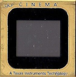
A DLP chip for cinema printing, manufactured by Texas Instruments.
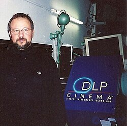
A prototype DLP Cinema projector from Texas Instruments, the Mark V model, 2000.
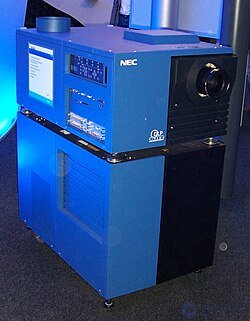
An NEC Cinema DLP projector in 2006.
DLP Cinema systems have been used and tested in movie theaters since 1999. In June 1999, "Star Wars: Episode I – The Phantom Menace" became the first film to be fully scanned and shown in theaters. Four theaters installed digital projectors to show the film. The same was done for the animated film "Tarzan" that same year. Later that year, "Toy Story 2" became the first film to be entirely created, edited and distributed in digital form, and more and more theaters installed digital projectors to show it. DLP Cinema was the first commercial digital cinema technology and is the leading digital cinema technology, with an approximately 85% share of the worldwide market as of December 2011. Digital cinema has some advantages over film, since film can be subject to color fading, jitter, scratches and dirt. Digital cinema makes it possible to keep the quality of film content stable over time. Today most film content is also shot digitally. The first fully digital feature film shot without the use of film stock was "Star Wars: Episode II – Attack of the Clones", released in 2002.
DLP Cinema does not manufacture projectors; it supplies the projection technology and works closely with Barco, Christie Digital and NEC, which build the projection units. DLP Cinema products are available to theater owners in several resolutions depending on the theater's needs. These include 2K for most cinema screens, 4K for large cinema screens, and S2K, developed specifically for small theaters, particularly in emerging markets around the world.
On February 2, 2000, Philippe Binant, technical manager of the digital cinema project at Gaumont in France, carried out Europe's first digital cinema projection using DLP Cinema technology developed by Texas Instruments. DLP is currently the market leader in professional digital cinema projection, largely thanks to its high contrast ratio and the available resolution compared with other digital front-projection technologies. As of December 2008, more than 6,000 DLP-based digital cinema systems had been installed worldwide.
DLP projectors are also used in RealD 3D and newer IMAX theaters to show 3D films.
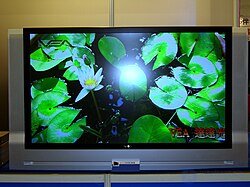
A 56-inch DLP rear-projection television
Since its commercial introduction in 1996, DLP technology has won market share in front projection and currently holds more than 50% of the worldwide front-projection market, as well as 85% of the worldwide digital cinema market. In addition, in the pico display category (small mobile displays), DLP technology held roughly 70% of the market. More than 30 manufacturers have used the DLP chipset to power their projection systems.
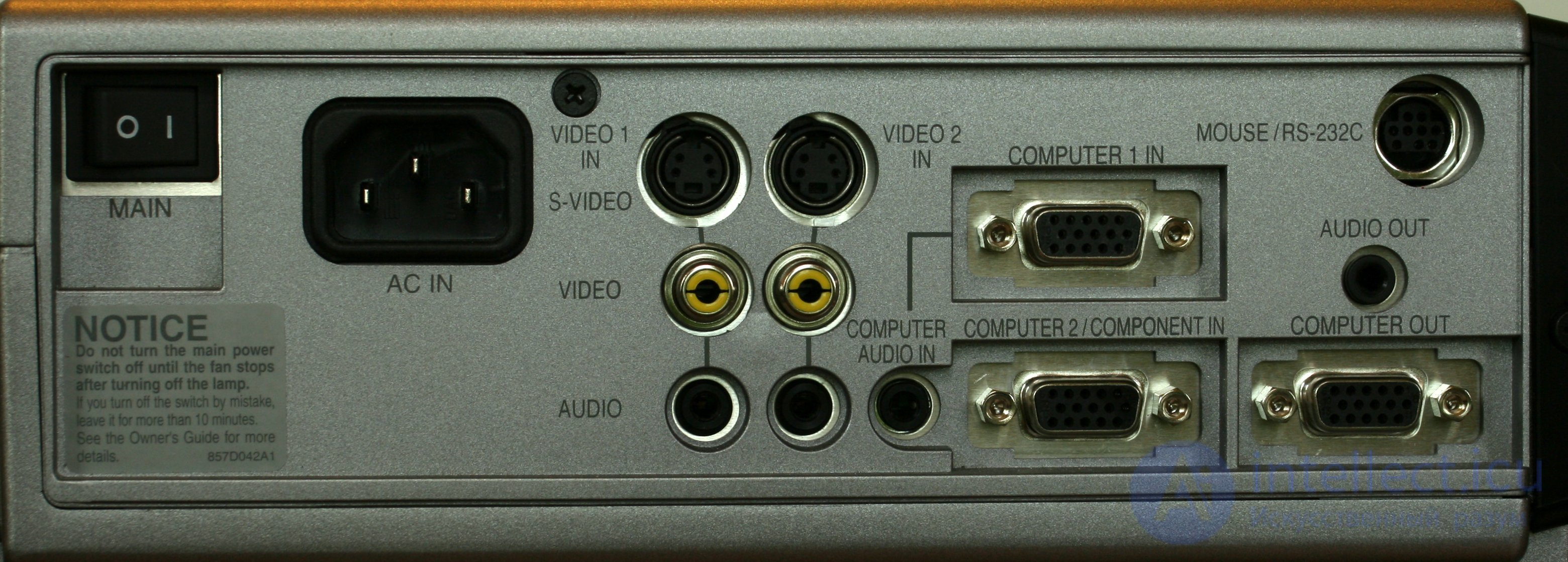
The rear panel of the Mitsubishi XD300U, showing the available output and input connectors.
The competing system most similar to DLP is LCoS ( liquid crystal on silicon ), which forms images using a fixed mirror mounted on the surface of the chip and uses a liquid crystal matrix (similar to a liquid crystal display ) to control the amount of light reflected. DLP-based television systems are also considered to be, arguably, less deep than traditional projection televisions.

Comments