
Lecture
The RHDA (video head assembly, or rotating head drum assembly) can be regarded as the main unit of any video cassette recorder or camcorder. Let us examine its construction, the possible design variants and the disassembly/reassembly procedure.
Attempts to record a television signal on magnetic tape were already being made in the 1940s. At first the intention was to use ordinary tape recorders with stationary magnetic heads, but with a higher tape speed and a wider magnetic tape. Many of these attempts were successful, yet the capabilities of machines using longitudinal recording completely ruled out their widespread use because of the short recording time. In 1953, for example, the RCA company (USA) demonstrated a machine with a tape speed of 9 m/s. On a reel 43 cm in diameter with a tape width of 12.7 mm the recording time was only about four minutes.
All subsequent progress in recording television and other wideband signals is associated with the use of magnetic heads rotating at high speed. This method was first implemented in 1956 in a video recorder made by Ampex (USA) that used transverse-scan recording. Its tape speed had been reduced to 39.7 cm/s [1].
Soviet developments were not far behind. In 1959 the first video recorder, developed at the Lenkinap plant, was demonstrated in Leningrad. It should be noted that at the time video recording equipment in the USA was classified as a strategic commodity and could not be sold to the Comecon countries, so our first video recorder was built entirely from domestic components and on the basis of in-house designs.
Further achievements in video recording are owed to the use of helical-scan recording of video signals on tape moving at a relatively low speed. It was first applied in reel-to-reel machines and later in cassette machines. Despite the many design variants, the main unit - the "heart" - of any video recorder was and remains the rotating head drum assembly (RHDA). It is used to record not only television signals but also audio signals, as well as various kinds of information in analog and digital form.
In the early 1970s pulse-code modulation (PCM) was adopted for professional audio recording. In practice it was tested in a system consisting of a U-MATIC format cassette video recorder and a Sony PCM-1630 converter. No modification of the production video recorder was required, since the two-channel stereo audio signals were converted by the PCM-1630 unit into PCM signals and then into a pseudo-television signal. With the appearance of consumer cassette video recorders, this method of recording sound also found consumer applications. PCM adapters were widely sold on the Japanese domestic market in the early 1980s. Sound recording by this method is still used today in HI-8 format equipment (mainly in camcorders).
Rotating heads for recording audio signals alone were also used in digital tape recorders of the R-DAT (DIGITAL AUDIO TAPE) format, which went on sale in 1987. The format was originally intended as a consumer one, but such recorders never became widespread in the home because of their high price. Nevertheless, R-DAT recorders are still produced by many companies today. They are now aimed mainly at professional use and at enthusiasts of high-quality sound reproduction (FOSTEX, HHB, Sony, TASCAM and others).
Naturally, RHDAs are also used in consumer cassette video recorders and in the recorder sections of camcorders of the VHS, VHS-C, VIDEO-8, S-VHS, S-VHS-C and MINI-DV formats. It should be noted that the recorded track patterns of the VHS, VHS-C, S-VHS and S-VHS-C formats are identical, i.e. the "compact" variants are not separate formats in the full sense. The RHDAs in VHS-C/S-VHS-C equipment, however, differ radically from their full-size counterparts, so here we shall treat them as different formats.
The RHDA serves as the "heart" of video recorders insofar as the quality of the recorded and reproduced video signals - and often the audio signals as well - depends directly on its characteristics. Failures and malfunctions of the various units and parts of the RHDA are not uncommon. A detailed understanding of their design and operation is therefore essential for effective repair and adjustment of consumer video recorders and camcorders.
The design features, geometric dimensions and characteristics of an RHDA are determined first of all by the recording format. Counting from the appearance of the first video recorders up to the present day, a great many different formats of magnetic recording with rotating heads can be named. Some of them became extremely widespread; others, on the contrary, remained only on paper. One definition of the concept runs as follows: a recording format is an ordered arrangement on the tape surface of the lines and tracks magnetized by various signals, ensuring compliance with the principle of interchangeability and unambiguously specifying the way the information is recorded and reproduced. The most significant formats are usually registered with the International Electrotechnical Commission (IEC).
Digital formats appeared in the 1990s. The struggle for their widespread adoption is being waged by such well-known companies as Sony (DIGITAL BETACAM, BETACAM-SX, DVCAM), Matsushita (PANASONIC-D3, D5, DV, DVCPRO) and JVC (DIGITAL-S). This concerns professional formats. As for consumer formats, the situation there has settled down, and most manufacturers produce equipment of the MINI-DV format (predominantly camcorders).
Unfortunately, consumer digital camcorders - and still more digital video recorders - have not yet become noticeably widespread here because of their high price ($1,000 and up). In addition, making full use of their capabilities requires a good computer with a capture card. MINI-DV cassettes are three times as expensive as HI-8 cassettes, which naturally makes the spread of such equipment even more difficult. With this in mind, we shall consider only the RHDAs used in the widely available consumer video equipment of the VHS/VHS-C/S-VHS/S-VHS-C, VIDEO-8 and HI-8 formats.
The requirements set by a format can be met in various ways, so RHDA designs differ widely. Since repair work - in particular the replacement of video heads - calls for a clear understanding of the design of the specific RHDA, the order of its disassembly/reassembly and the details of its servicing, it makes sense to classify the design variants of the various manufacturers.
Regardless of the manufacturer, RHDAs contain the following units: the upper drum (UD), on which the magnetic heads are mounted; the rotary transformer (RT); the lower drum (LD), mounted at an angle on the base plate of the tape transport mechanism; and the brushless DC motor (BLDC) that drives the RHDA. In some Toshiba video recorder models the RHDA also includes a preamplifier together with the generator that powers it (Toshiba V856G and others). In a number of its video recorders JVC incorporated into the RHDA units that provide the required tilt of the assembly relative to the chassis at different tape speeds in order to obtain a noise-free picture (JVC HR-DD949EE and others).
Although the RHDA diameter is considered one of the format conditions (for VHS, IEC publication 774 of 1983), a track pattern conforming to one format or another can be obtained with various diameters. In particular, VHS equipment uses RHDAs 62 mm in diameter (the bulk of the equipment) and 41.33 mm (in full-size camcorders). Small-size RHDAs are also widely used in most VHS-C/S-VHS-C camcorder models. The tape transport of such camcorders cannot be used with ordinary VHS cassettes. At the same time, with a special adapter a compact cassette can be loaded into any VHS video recorder. Format compatibility is therefore incomplete. This is another reason why the VHS-C format is often regarded as a separate one.
Most eight-millimeter equipment uses RHDAs 40 mm in diameter. Camcorders also use RHDAs 26.7 mm in diameter (Sony CCD-TR505E and others). The wrap angle of the tape around the drum depends on its diameter: in VHS/S-VHS it is 180°, in VHS-C 270°, and in VIDEO-8/HI-8 220° (with a diameter of 26.7 mm, almost 360°).
Out of the whole variety of RHDA designs seven nominal variants (types) with differing engineering solutions can be distinguished (in the author's opinion), six of which are described in the table. The seventh type comprises special RHDA designs with rotating preamplifiers, with so-called movable video heads, with a variable tilt angle, and so on.
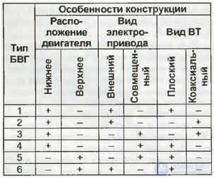
Figure 1 shows RHDAs of the first three types, of which type 1 is used in the VIDEO-8 format with an RHDA diameter of 40 mm, while types 2 and 3 are used in the VHS/S-VHS formats with RHDA diameters of 41.33 and 62 mm respectively.
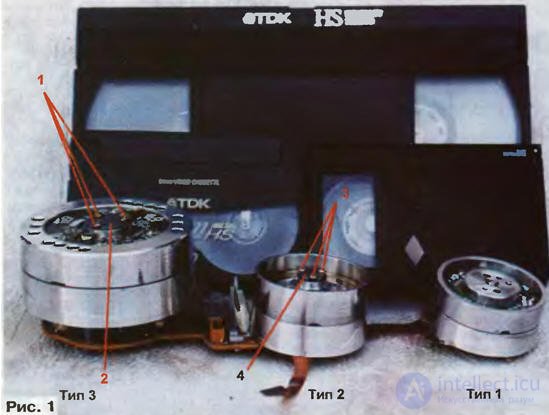
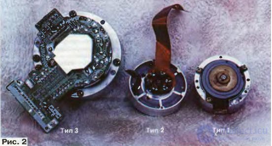
Figure 2 shows the lower drums of these RHDA types viewed from below; type 1 is used in Samsung VP-U12/U15 and similar camcorders, type 2 in Panasonic NV-V9000/MS4/AG455/AG-DP200 camcorders, and type 3 in Panasonic NV-ND70/90/95/100/F55/65/FS88/200/AG5260/5700 and other Matsushita video recorders.
Each company classifies the specific designations of its RHDAs in its own way. Markings are usually not applied to them, since the RHDA is an assembled unit. Even the upper drum is by no means always marked, let alone the lower drum and the rotary transformer. However, if information on the applicability of RHDA units is available, in many cases analogs can be selected for machines that are hard to repair (so-called write-offs). There is practically no point in looking for such data in the literature, since manufacturers are reluctant to make information of this kind publicly available. It is therefore very useful for repair technicians and practicing radio amateurs to record the markings of the units in the equipment they repair in an archive of their own.
As an example, let us look at the applicability of some Matsushita lower drums (the applicability of upper drums requires separate treatment). The lower drum marking is usually painted on its side surface. Lower drum VEG1343A is used in the line of two-head Panasonic video players and video recorders produced in 1997-1999: NV-SP10/SR30/50/55/60/PO5 and others. Lower drum VEG0758 is used in three-head Panasonic video recorders produced in the late 1980s and early 1990s: NV-L20/J30 and others. Lower drum VEG1023 is fitted in four-head Panasonic video recorders of the SUPER DRIVE series: NV-SD20/25 and others. Panasonic NV-SR70/80/90/HP10 stereo video players with four heads use lower drum VEG1220. Panasonic NV-F55/F65 stereo video recorders with six heads use lower drum VEG0766. Under certain conditions it is interchangeable with lower drum VEG1221, fitted in the Panasonic SUPER DRIVE video recorder models NV-ND70/90/95/100/AG5260 and others.
Upper drums, and still more complete RHDAs, are very expensive and often so scarce that in some cases, if they fail, video recorders - and camcorders especially - become completely unrepairable, or the cost of repair is unrealistic for their owners. Particular care should therefore be taken when disassembling and reassembling an RHDA.
In many Panasonic video recorder models with a type 3 RHDA, faults caused by dried-out lubricant, contamination and wear of the sleeve bearings occur fairly often. This produces a mechanical rumble, the picture appears to sway horizontally, the stereo sound channels cut out, and so on. As a rule such defects can be eliminated, which requires disassembling and reassembling the RHDA. Before starting, the upper drum must always be secured with a shim inserted into the gap between the upper and lower drums. A safety razor blade in its wrapper, for example, is suitable for this purpose.
Disassembly begins by removing the three fastening screws 1 shown in Fig. 1, the ground-wire current collector having first been detached. The slots of these screws generally call for a special screwdriver, but a 1.6 or 1.5 mm hex socket wrench can be used. Sets of such wrenches are sold at radio markets (for example, the VIDEO SERVICE TOOL VHS/BETA 8034-549-11 set and the like).
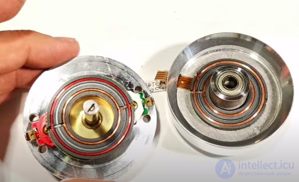
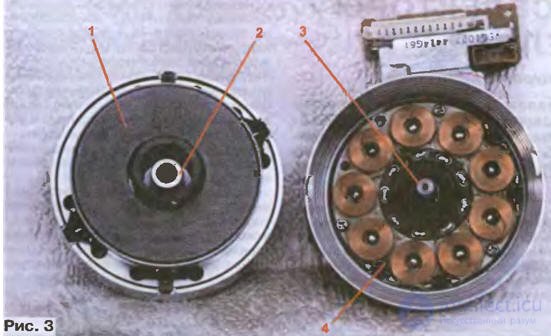
Next, remove cover 2, which also serves as the upper sleeve bearing. Keep in mind that magnet 1 of the motor rotor shown in Fig. 3 in the disassembled state is firmly attracted to stator 4, so the rotating drum must never be turned (the spacer inserted earlier protects the video heads from damage).
The next operation is removing the split retaining washer located under cover 2 (see Fig. 1). A special tool is generally required to remove it, but miniature pliers or tweezers can also be used. The width of their tips must not exceed 1.6 mm. Prying washers out with screwdrivers, though often practiced, is not recommended, since it usually damages the motor rotor hub, which is made of aluminum alloy; after that, normal operation of the units - especially stereo and editing models - can very rarely be achieved, because the alignment of the rotating and stationary drums is disturbed and eccentricity appears.
The next stage is removing the rotating drum together with the motor rotor and the rotary transformer. This must be done very carefully, without disturbing the alignment, so as not to damage the fragile ferrite cores of the rotary transformer or its windings. Then clean dirt off steel carrier shaft 3 (Fig. 3) and the inner surface of sleeve bearing hub 2 with an alcohol-gasoline mixture (or with alcohol or gasoline alone) and lubricate the bearings with a small amount of sewing machine oil (preferably a refined grade, or so-called clock oil).
After this, put the rotating drum back into its original position, remembering to insert the retaining spacer. Returning the split washer to its place is not essential, since the rotor magnet is attracted to the base with quite sufficient force. Finally, close the shaft with cover 2 (see Fig. 1), having first cleaned its inner surface and lubricated it with a special non-thickening grease (Morliton, purified petroleum jelly, and the like; automotive grease must not be used). Tighten fastening screws 1 gradually and alternately, so that the cover is not skewed.
In most cases the operations described are quite sufficient to restore normal, quiet operation of the rotating head drum assembly. In rare cases, the inner surface of bearings 2 (Fig. 3) may need to be polished with a twist of cotton cloth rubbed with polishing compound.
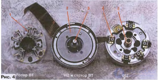
Type 2 head drum assemblies have a similar design. One is shown disassembled in Fig. 4. It is taken apart after unscrewing screws 3 and removing cover 4 (see Fig. 1). The differences from the type 1 assembly are the absence of a split retaining washer and the fact that the leads of the video heads on rotating drum 4 (Fig. 4) are connected to the windings of rotary transformer rotor 1 through gold-plated spring contacts (in the type 1 assembly these are soldered joints). Also visible in Fig. 4 are motor rotor 2, carrier shaft 3 and bearing hub 5.
The design features and the disassembly/assembly procedures for type 5 head drum assemblies are covered in , and those for other types in the albums "Tape transport mechanisms of VCRs and camcorders: repair and adjustment", sold at electronics markets.
The largest number of head drum assembly failures, including those caused by natural wear, occur in the rotating drum. There are many dozens of its designs and types. Information on their application and interchangeability is of great practical interest both to repair technicians and to electronics hobbyists

Comments