
Lecture
Resistor–transistor logic ( RTL ), sometimes also known as transistor–resistor logic ( TRL ), is a class of digital circuits built using resistors as the input network and bipolar junction transistors (BJTs) as the switching devices. RTL is the earliest class of transistorised digital logic circuits; it was superseded by diode–transistor logic (DTL) and transistor–transistor logic (TTL).
RTL circuits were first built from discrete components, but in 1961 they became the first family of digital logic devices to be produced as a monolithic integrated circuit. RTL integrated circuits were used in the Apollo Guidance Computer, whose development began in 1961 and which made its first flight in 1966.
A bipolar transistor switch is the simplest RTL gate (an inverter, or NOT gate), implementing logical negation. It consists of a common-emitter stage with a base resistor connected between the base and the input voltage source. The role of the base resistor is to extend the transistor's very small input voltage range (about 0.7 V) up to a logic "1" level (about 3.5 V) by converting the input voltage into a current. Its resistance is determined by a trade-off: it is chosen low enough to saturate the transistor and high enough to obtain a high input resistance. The role of the collector resistor is to convert the collector current into a voltage; its resistance is chosen high enough to saturate the transistor and low enough to obtain a low output resistance (a large fan-out).
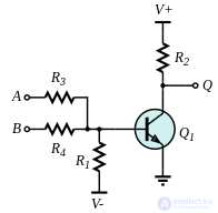
Circuit of a single-transistor RTL NOR gate.
When two or more base resistors (R 3 and R 4 ) are used instead of one, the inverter becomes a two-input RTL NOR gate (see the figure on the right). The logical OR operation is performed by successively applying the two arithmetic operations of addition and comparison (the input resistor network acts as a parallel voltage summer with equally weighted inputs, and the following common-emitter transistor stage acts as a voltage comparator).with a threshold of about 0.7 V). The equivalent resistance of all the resistors connected to logic "1" and the equivalent resistance of all the resistors connected to logic "0" form the two branches of a composite voltage divider driving the transistor. The base resistances and the number of inputs are chosen (limited) so that a single logic "1" is enough to produce a base–emitter voltage above the threshold and, as a consequence, to saturate the transistor. If all the input voltages are low (logic "0"), the transistor is cut off. The pull-down resistor R 1 biases the transistor to the appropriate on–off threshold. The output is inverted, since the collector–emitter voltage of transistor Q 1is taken as the output signal and is high when the input signals are low. Thus an analogue resistive network and an analogue transistor stage together perform the logical OR function.
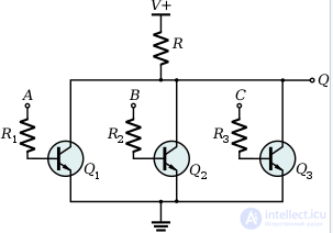
Circuit of a multi-transistor RTL NOR gate as used in the integrated circuits of the Apollo Guidance Computer.
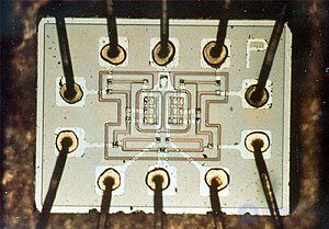
Photograph of a chip containing two three-input NOR gates, used to build the Apollo Guidance Computer. The connections (clockwise from the centre top): ground, inputs (3), output, power (V cc ), output, inputs (3). The six transistors (two groups of three) are in the centre. The thin wires running from the terminals to the transistors are resistors.
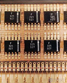
Flatpack RTL NOR gate integrated circuits in the Apollo Guidance Computer
The limitations of the single-transistor RTL NOR gate are overcome by a multi-transistor RTL implementation. It consists of a set of transistor switches connected in parallel and driven by the logic inputs (see the figure on the right). In this configuration the inputs are completely separated, and the number of inputs is limited only by the small leakage current of the cut-off transistors at a logic "1" output. This same idea was later used to build DCTL, ECL, some TTL (7450, 7460), NMOS and CMOS gates.
To make the output of bipolar transistors stable and predictable, their base inputs (V b or the voltage at the base terminal) are biased.
The main advantage of RTL technology was that it used a minimal number of transistors. In circuits built from discrete components, before integrated circuits appeared, transistors were the most expensive component to manufacture. Early production of IC logic (for example, Fairchild in 1961) briefly used the same approach, but quickly moved on to circuits with better characteristics, such as diode–transistor logic and then transistor–transistor logic (from 1963 at Sylvania Electric Products), since diodes and transistors were no more expensive than resistors on a chip.
A drawback of RTL is the high power dissipation when the transistor is switched on, caused by the current flowing in the collector and base resistors. This requires supplying more current and removing heat from RTL circuits. By contrast, TTL circuits with a "totem-pole" output stage minimise both of these requirements.
Another limitation of RTL is the restricted number of inputs: 3 inputs is the limit for many circuits before it loses useful noise immunity entirely. [ citation needed ] It has a low noise margin. Lancaster says that integrated-circuit RTL NOR gates (which have one transistor per input) can be built with "any reasonable number" of logic inputs, and gives an example of an 8-input NOR gate.
A standard integrated-circuit RTL NOR gate can drive three other similar gates. Alternatively, its output power is enough to drive two standard integrated-circuit RTL "buffers", each of which can drive up to 25 other standard RTL NOR gates.
Various companies used the following methods to speed up discrete RTL.
Transistor switching speed has increased steadily from the time of the first transistorised computers up to the present day. The GE Transistor Manual (7th ed., p. 181, or 3rd ed., p. 97, or the editions in between) recommends gaining speed by using high-frequency transistors, capacitors, or a diode between the base and the collector (shunt negative feedback) to prevent saturation.
Placing a capacitor in parallel with each input resistor reduces the time the driving stage needs to forward-bias the base–emitter junction of the driven stage. Engineers and technicians use "RCTL" (resistor–capacitor–transistor logic) to refer to gates fitted with "speed-up capacitors". The circuits of Lincoln Laboratory's TX-0 computer included some RCTL. Capacitor-based techniques were, however, unsuitable for integrated circuits.
Using a high collector supply voltage and diode clamping reduced the charging time of the collector and wiring capacitance. Such a circuit required a diode clamp on the collector at the design logic level. This technique was also applied to discrete DTL (diode–transistor logic).
Another method, familiar from discrete-device logic circuits, used a diode and a resistor, a germanium and a silicon diode, or three diodes in a negative feedback circuit. These diode circuits, known as various Baker clamps, reduced the voltage applied to the base as the collector approached saturation. Since the transistor went into saturation less deeply, fewer charge carriers accumulated in it. Consequently, less time was needed to clear the stored charge while the transistor was turning off. A low-voltage diode intended to prevent transistor saturation was applied in integrated logic families using Schottky diodes, as in Schottky TTL.

Comments