
Lecture
In mechanics, with a high degree of accuracy, liquids and gases are regarded as continuous media, distributed continuously throughout the part of space they occupy. The density of a liquid depends weakly on pressure. The density of gases, on the other hand, depends significantly on pressure. However, experience shows that in many problems the compressibility of a gas, like that of a liquid, can be neglected, and a single notion of an incompressible fluid, whose density is the same everywhere, can be used. Hydrostatics is an ancient science. Basing himself, for example, on the equilibrium properties of an incompressible fluid, the French scientist B. Pascal established the law of communicating vessels (known, it is true, already to Leonardo da Vinci). Pascal's studies on hydrostatics were published in 1663, after his death. We shall begin this chapter with them.
The statement known as Pascal's law or the law of hydrostatics, but equally valid for gases, states:
A liquid enclosed in a sealed vessel transmits the pressure exerted on it equally in all directions.
This property of a liquid can be demonstrated using a device called Pascal's ball (Fig. 9.1).
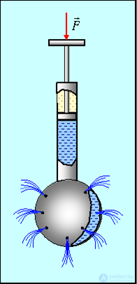
Fig. 9.1. Pascal's ball
Let us mentally draw a small area  within some volume of liquid that is in equilibrium. Individual particles of the liquid act on one another and, in particular, on the area with a force that depends on the degree of compression. This action is characterized by the pressure
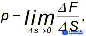
where  is the resultant of all the forces with which the liquid acts on the area.
In the SI system, the unit of pressure is the pascal (Pa):

One pascal is the pressure produced by a force of one newton, uniformly distributed over a surface normal to it with an area of 1 m2.
For example, if a pin is pressed into the surface of a table with a force of 10 N, and the area of its point is 0.05 mm2, then the pressure of the pin on the table equals
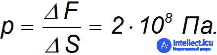
Fig. 9.2 shows the characteristic scales of pressures encountered in nature.
Fig. 9.2. Scales of pressures encountered in the surrounding world
Note that pressure is a scalar quantity, to which the notion of direction is not applicable. The force, however, with which a liquid presses on an elementary area  , is always directed along the normal to the area.
If a thin plate of area S is placed inside a liquid, then the liquid will exert a pressure force on it, perpendicular to its surface (Fig. 9.3).
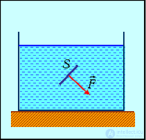
Fig. 9.3. Pressure force in a liquid
Indeed, if the force were not directed at a right angle to the chosen area, then its tangential component, owing to the absence of resistance to shear, would set the liquid in motion, which contradicts the condition of being at rest.
One manifestation of Pascal's law can be observed in a hydraulic press (Fig. 9.4).
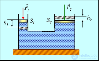
Fig. 9.4. Operating principle of a hydraulic press
Two communicating vessels are filled with liquid and closed by pistons of different area. By Pascal's law, the pressures under the pistons are equal p1 = p2, that is
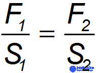
or
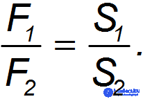
Thus, the pressure force of the second piston is greater than the pressure force of the first by exactly the factor by which the area of the second piston is greater than the area of the first. The hydraulic press is a simple mechanism allowing tremendous forces to be developed, used for pressing various products from metals and plastics. Let us denote h1 and h2 as the piston strokes. Owing to the practical incompressibility of the liquid, the volumes transferred from one cylinder to the other are equal:
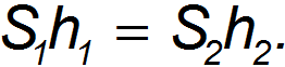
The work done by the forces F1(2) over one stroke is calculated as
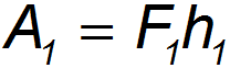
and
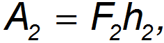
so that their ratio will be
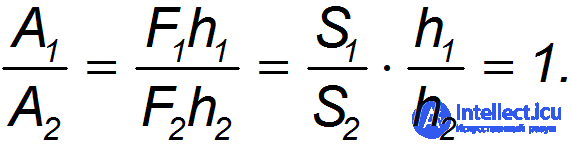
As expected, the press gives a gain in force, but not in the work done.
The same principle underlies the design of a hydraulic lift (Fig. 9.5). Note that the cross-sectional area of the first cylinder, in which the piston pumping the oil moves back and forth, is significantly smaller than the cross-sectional area of the cylinder that guides the motion of the second piston. The second piston transmits the force to a rod rigidly connected to the platform on which the load — a car — is raised. At the same oil pressure in the system, the pressure forces with which the oil acts on the pistons differ significantly.
Opening valve 3 causes the oil, under the action of pressure, to flow into the storage tank.
Fig. 9.5. Operation of a hydraulic lift
Let us determine the pressure inside a liquid, considering it incompressible, that is, considering its density unchanged regardless of depth. Let an external pressure p0 act on the liquid in the vessel. Let us mentally isolate a vertical cylinder in the liquid with cross-section S and height h (Fig. 9.6).
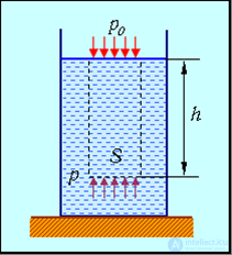
Fig. 9.6. Pressure of a liquid in a gravitational field
An external pressure p0 acts on the upper layer of the liquid, and is also transmitted to the other layers of the liquid. To this pressure, in the lower layers, is added the pressure created by the weight of the layers of liquid located above. A force F0 = p0S acts on the upper base of the cylinder, and a force F = pS acts on the lower base, where p is the pressure at depth h. In addition, the force of gravity of the column of liquid within the volume of the cylinder acts vertically downward:

where ρ is the density of the liquid, and hS is its volume.
Let us write the equilibrium condition for the isolated column of liquid:
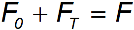
or

Consequently, the pressure in the liquid at depth h will be equal to

where ρgh is the hydrostatic pressure of the liquid, due to its weight.
According to the formula obtained, the pressure force on the lower layers of liquid will be greater than on the upper ones. Therefore a buoyant force, called the Archimedes' force, acts on a body immersed in a liquid. Let us immerse in a liquid, to depth h, a rectangular parallelepiped with base area S and edge height a (Fig. 9.7).
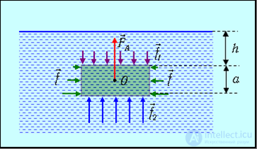
Fig. 9.7. Archimedes' force acting on a body immersed in a homogeneous liquid
The pressure at depth h equals

and therefore a force acts on the upper base

At depth h+a the pressure equals

and therefore a force acts on the lower base

The resultant of these two forces is directed upward and is equal in magnitude to

Here Sa = V is the volume of the immersed part of the body, and m = pV is the mass of liquid (gas) of the same volume.
The equation obtained represents the mathematical formulation of Archimedes' law:
A body immersed in a liquid (gas) is acted on by a buoyant force equal to the weight of the liquid (gas) displaced by the body.
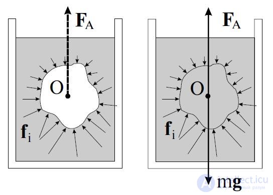
Fig. 9.8. Illustration of Archimedes' law
Let us now consider the motion of a liquid. The simplest case is so-called steady flow. There is no contradiction in using the word “steady” next to the word “flow,” which implies motion of the elements of the liquid.
Steady flow is a flow in which the velocity of the liquid at each given point remains constant both in magnitude and direction.
Elements of the liquid come and go, but at a given point each newly arrived element acquires the velocity that corresponds to that point. Therefore steady flow can be characterized by a velocity field, given by a vector function v(r) of the spatial coordinates. Graphically, the velocity field is depicted using streamlines.
An oriented line, the tangent to which at each point coincides in direction with the velocity vector at that point in space, is called a streamline.
Fig. 9.9 shows a streamline in a region of fluid flow.
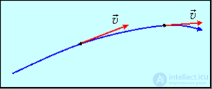
Fig. 9.9. A streamline
Recalling what we know from the school physics course about electricity, we can say that streamlines are the analogue of field lines.
Let us agree to draw streamlines so that their density (characterized by the ratio of the number of lines  to the value of the area
  perpendicular to them, through which they pass) is proportional to the magnitude of the velocity at that location. The part of the liquid bounded by streamlines is called a stream tube. For steady flow, the shape and arrangement of the streamlines do not change with time.
Let us consider some stream tube. Everywhere below we assume the cross-sectional area of the tube to be sufficiently small, so that the velocity of the liquid can be considered the same at all points of the cross-section. During time dt, a volume of liquid Svdt passes through an arbitrary cross-section S of it (Fig. 9.10–1).
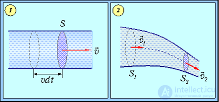
Fig. 9.10 Stream tubes
Let us choose two of its cross-sections S1 and S2 (Fig. 9–2). During time dt, through cross-section S1 a volume of liquid S1v1dt will pass, where v1 is the flow velocity of the liquid at points of cross-section S1. Similarly, through cross-section S2, during the same time dt, a volume of liquid S2v2dt will pass, where v2 is the flow velocity of the liquid at points of cross-section S2. From the condition of incompressibility of the liquid it follows that the volumes of liquid that entered the region between cross-sections S1, S2 and left it are equal:
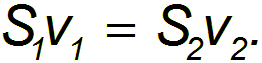
Consequently,
In an incompressible liquid, the quantity Sv is the same in any cross-section of one and the same tube, in other words, this quantity is constant along the stream tube:
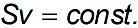
This relation is one of the forms of the theorem of continuity of a jet. This theorem expresses the fact of incompressibility of the liquid.
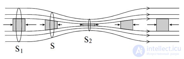
Fig. 9.11. Jet velocity at different cross-sections of a tube
The theorem of continuity of a jet is applicable to real liquids, as well as to gases, in the case when their compressibility can be neglected. A direct consequence of the theorem is the well-known fact: at a narrowing of a pipe, the flow velocity increases. Moreover, an analogous theorem also exists in the theory of electromagnetism, where it is related to the conservation of electric charge.
Example. Let us estimate the throughput of one lane of a stretch of highway. Note that the “Traffic Regulations” recommend keeping a distance L between cars, which in metres is numerically equal to half the speed of travel, expressed in km/h.
In this problem we are, in essence, also dealing with the continuity equation — in the absence of a “traffic jam” on the road, the same number of cars must pass through each cross-section of it. The flow of cars equals
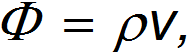
where v is the average speed of travel, and ρ is the linear “density” of cars on the road, that is, the number of cars per unit length. If l is the average length of a car, and L is the average distance between them, then
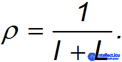
The recommendation of the “Traffic Regulations” can be expressed mathematically in the form of a formula:
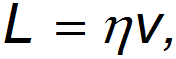
where

is the “safety factor.” As a result, we arrive at the expression:
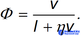
For a numerical estimate, let us take l = 3 m, and v = 60 km/h = 16.67 m/s (the permitted speed of travel in cities). We then obtain:

that is, each lane is able to pass 30 cars per minute.
When the speed of travel is increased to v = 90 km/h = 25 m/s, the throughput increases quite insignificantly: in this case we find

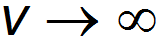
Even in the limit of infinitely large speed of travel
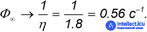
the limiting value of the flow
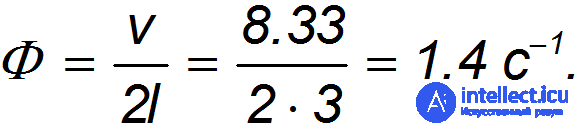
When the speed of travel is reduced, say, to v = 30 km/h = 8.33 m/s, the throughput becomes

Far more “effective” is failing to keep a safe distance. Say, with a distance L equal to the length l of the car body, and a speed of travel v = 30 km/h, we obtain for the flow:
But it is hardly the case that even a threefold increase in the throughput of a highway should be achieved at the expense of a decrease in traffic safety.
When a liquid flows, its individual layers generally flow at different velocities, sliding relative to one another, as a result of which friction forces arise between them. These forces are called forces of internal friction. They arise not only in liquids, but also in gases.
A liquid in which internal friction (viscosity) is completely absent is called ideal.
Let us isolate, in a steadily flowing ideal liquid, a stream tube bounded by cross-sections  and
and  , along which the liquid flows from left to right (Fig. 9.12). Let the following be given at cross-section : the flow velocity
  , the pressure
  , and the height
  at which this cross-section is located. Similarly, at cross-section the flow velocity
  , the pressure
  , and the height
  are given.
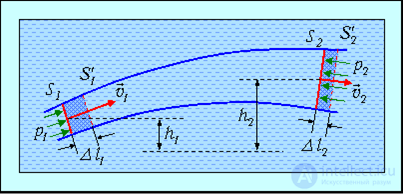
Fig. 9.12. Deriving Bernoulli's equation
During time  , the volume of liquid will shift along the stream tube, with cross-section moving to position
  , having traversed a distance
  , and cross-section moving to position
  , having traversed a distance
  . By virtue of the equation of continuity of the jet, the shaded volumes will be of equal magnitude:
  .
.
The energy of each particle of liquid consists of its kinetic energy and its potential energy in the gravitational field. The total energy of the flow passing during time through cross-section equals

An analogous expression for the energy of the flow is obtained for cross-section :

In steady flow, no energy accumulates between cross-sections and . In an ideal liquid there are no friction forces, so that mechanical energy is not lost anywhere. Consequently, the change in the total energy of the liquid is equal to the work done by external forces

The pressure forces on the lateral surface of the stream tube are perpendicular at each point to the direction of displacement of the particles, and therefore do no work. Only the work of the pressure forces applied at cross-sections and is nonzero. This work equals

Equating the change in the energy of the flow  to the work of the pressure forces
  , we find:

Dividing by  and moving the terms with matching indices to one side of the equation, we obtain:

Cross-sections and were chosen completely arbitrarily. Therefore we can assert that
In a steadily flowing ideal incompressible liquid, in any cross-section of a stream tube, the quantity
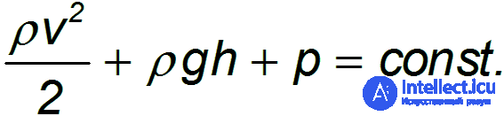
has one and the same value, in other words, along the stream tube this quantity is constant
The relation we have obtained is called Bernoulli's equation. This equation expresses the law of conservation of mechanical energy in the steady flow of an incompressible ideal liquid.
In the particular case of horizontal flow of a liquid  , Bernoulli's equation takes the form
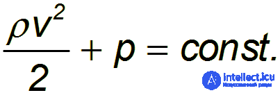
From the continuity equation

it follows that at a narrowing of the flow its velocity increases, and from Bernoulli's equation — that the pressure falls at that location.
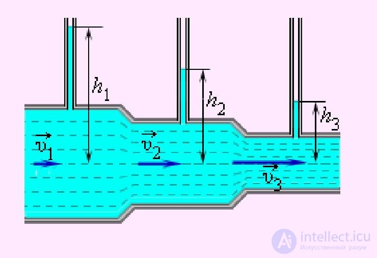
Fig. 9.13. Fluid velocity and pressure as a function of the tube cross-section
When ships travelling on parallel courses are too close to each other, the pressure between them drops, and the pressure of the outer flow pushes them together, which can lead to a collision of the vessels.
Example. A small hole is made in a vessel. The height of the liquid above the hole is  . Let us find the velocity of the outflowing jet.
Let us apply Bernoulli's equation. As cross-section let us take the surface of the liquid, and as cross-section let us take the hole that was made. The pressures at both cross-sections can be considered constant (and equal to atmospheric). The velocity of the liquid at cross-section can be neglected (if the area of the vessel is much greater than the area of the hole: >> ). Then we have:
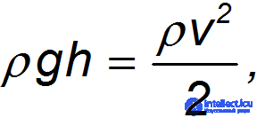
where is the height of cross-section above cross-section (that is, the level of the liquid above the hole), and  is the outflow velocity of the liquid from the hole. We obtain as a result:
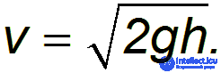
This relation is called Torricelli's formula. Note that the velocity of the outflowing jet equals the velocity of a freely falling body from the same height. This is not surprising, since both results are based on the law of conservation of energy for motion in a uniform gravitational field.
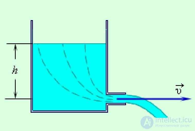
Fig. 9.14. Outflow of liquid from a hole
In deriving Bernoulli's equation, we neglected the compressibility of the liquid. As for gases, their compressibility is much greater than that of liquids. Let us obtain an estimate of the applicability of Bernoulli's equation to the flow of gases. The quantity  , called the dynamic pressure, must be small compared to the static pressure
  . Then the pressure fluctuations due to the flow of the gas will be small and its compressibility can be neglected. Consequently, the criterion for the applicability of Bernoulli's equation to gases is the inequality
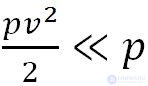
or
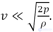
Let us give a numerical estimate. Under normal conditions the air pressure is approximately 105 Pa, and the density of air is 1.29 kg/m3. Hence
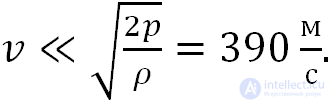
This value is close to the speed of sound and differs from it only by the factor 2 under the root sign: in the expression for the speed of sound, the adiabatic index  stands under the root sign, equal for air at room temperature to 1.4. As we shall see later, this is not a coincidence, so the criterion for the applicability of the “incompressible fluid” approximation to a gas, in which it is treated as incompressible, can be formulated as follows. The compressibility of a gas can be neglected at flow speeds much lower than the speed of sound in that gas:

At such speeds we can apply Bernoulli's equation to gases with the same success as to liquids.
Ever since Galileo's experiments at the Leaning Tower of Pisa it has been known that all bodies fall in a gravitational field with the same acceleration g.
However, everyday experience points to something else: a light feather falls more slowly than a heavy metal ball. The reason is understood — air resistance.
Equations of motion. If we restrict ourselves to the case of translational motion of non-rotating bodies in a stationary resisting medium, the drag force will be directed against the velocity. In vector form it can be written as
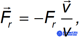
where  — is the absolute value of this force, and
  — is the magnitude of the body's velocity. Accounting for the resistance of the medium changes the form of the equations of motion of a body thrown at an angle to the horizontal:
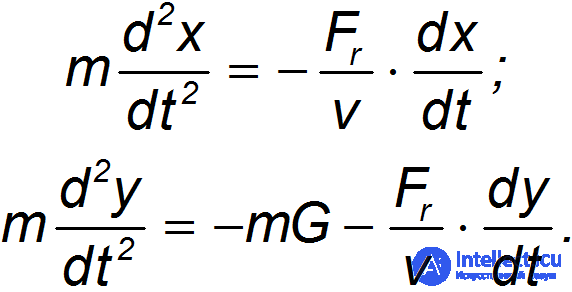
The equations given also take into account the buoyant Archimedes force acting on the body: the acceleration of free fall g is replaced by a smaller value
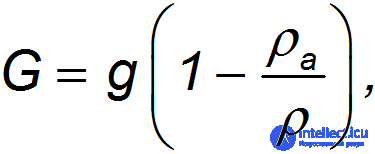
where  — is the density of the medium (for air = 1.29 kg/m3), and
  — is the average density of the body.
Indeed, the weight  of a body in a medium is reduced by the magnitude of the buoyant Archimedes force

Expressing the volume  of the body through its average density
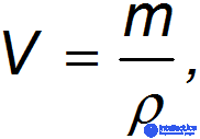
we arrive at the expression
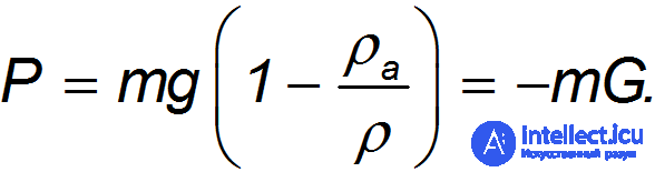
In the presence of air resistance the speed of a falling body cannot grow without bound. In the limit it approaches some steady value, which depends on the characteristics of the body. If the body has reached the terminal fall speed  , then from the equations of motion it follows that the drag force equals the weight of the body (taking into account the Archimedes force):
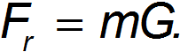
The drag force , as we shall soon confirm, is a function of the fall speed. Consequently, the resulting expression for the drag force represents an equation for determining the terminal fall speed . It is clear that in the presence of a medium, the body's energy is partly spent overcoming its resistance.
Reynolds number. Of course, the equations of motion of a body in a fluid cannot even begin to be solved while we know nothing about the magnitude of the drag force. The magnitude of this force depends substantially on the character of the flow of the oncoming gas (or liquid) stream around the body. At low speeds this flow is laminar (that is, layered). It can be pictured as the relative motion of layers of the medium that do not mix with one another.
Laminar flow of a liquid is demonstrated in the experiment shown in fig. 13.
As already noted in Ch. 9.3, when layers of liquid or gas move relative to one another, resistance forces to the motion arise between these layers, which are called internal friction forces. These forces are due to a special property of fluids — viscosity, which is characterized numerically by the coefficient of viscosity  . Let us give characteristic values of for various substances: for air ( = 1.8·10-5 Pa·s), water ( = 10–3 Pa·s), glycerin ( = 0.85 Pa·s). An equivalent notation for the units in which the coefficient of viscosity is measured: Pa·s=kg·m–1·s–1.
Between a moving body and the medium there always exist forces of adhesion, so that immediately adjacent to the surface of the body the layer of gas (liquid) is completely held back, as if “sticking” to it. It rubs against the next layer, which lags slightly behind the body. That layer, in turn, experiences a friction force from the side of an even more distant layer, and so on. Layers quite far from the body can be considered at rest. A theoretical calculation of internal friction for the motion of a sphere of diameter D leads to Stokes' law:
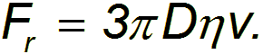
Substituting Stokes' law into the expression for the drag force at steady motion, we find the expression for the terminal fall speed of a sphere in a medium:
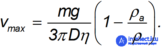
It can be seen that the lighter the body, the lower its speed of fall in the atmosphere. The resulting equation explains to us why a downy feather falls more slowly than a steel ball.
When solving real problems, for example calculating the terminal speed of a skydiver during a delayed-opening jump, one should not forget that the friction force is proportional to the body's speed only for a relatively slow laminar oncoming air flow. As the body's speed increases, air vortices arise around it, the layers mix, the motion at some point becomes turbulent, and the drag force increases sharply. Internal friction (viscosity) ceases to play any noticeable role.
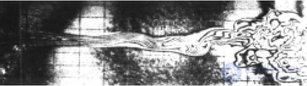
Fig. 9.15 Photograph of a liquid jet during the transition from laminar to turbulent flow (Reynolds number Re=250)
The emergence of the drag force can then be pictured as follows. Suppose a body has traveled a distance  in the medium. With drag force , the work expended on this is
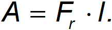
If the cross-sectional area of the body is  , then the body will “run into” particles occupying a volume
  . The total mass of particles in this volume equals · Let us imagine that these particles are fully carried along by the body, acquiring speed . Then their kinetic energy becomes equal to
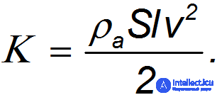
This energy did not appear out of nowhere: it is created at the expense of the work of external forces overcoming the drag force. Hence A=K, from which
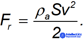
We see that now the drag force depends more strongly on the speed of motion, becoming proportional to its second power (cf. Stokes' law). Unlike internal friction forces, it is often called the dynamic frontal drag force.
However, the assumption of complete entrainment of the medium's particles by the moving body turns out to be too strong. In reality any body is streamlined by the flow to one degree or another, which reduces the drag force. It is customary to use a so-called drag coefficient C, writing the frontal drag force in the form:
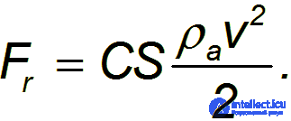
At turbulent flow, over a certain interval of speeds, C does not depend on the speed of motion of the body, but does depend on its shape: for instance, for a disk it equals one, and for a sphere approximately 0.5.
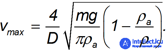
Substituting the formula for the frontal drag force into the expression for the drag force at steady motion, we arrive at an expression for the terminal fall speed of a sphere (at C = 0.5) that differs from the formula obtained earlier:
Applying the formula found to the motion of a skydiver weighing 100 kg with a parachute cross-sectional size of 10 m, we find
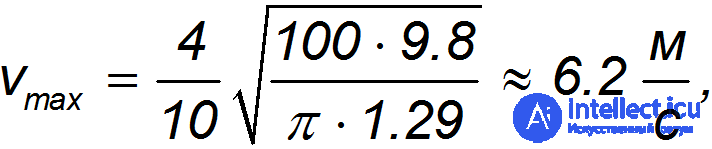
which corresponds to the landing speed of a jump without a parachute from a height of 2 m. It can be seen that for describing the motion of a skydiver the formula corresponding to turbulent air flow is more suitable.
The expression for the drag force with the drag coefficient is convenient to use over the entire range of speeds. Since at low speeds the resistance regime changes, the drag coefficient in the region of laminar flow and in the transitional region to turbulent flow will depend on the speed of the body. However, a direct dependence of C on is impossible, since the drag coefficient is dimensionless. Hence, it can only be a function of some dimensionless combination involving the speed. Such a combination, which plays an important role in hydro- and aerodynamics, is called the Reynolds number  (see topic 1.3).
The Reynolds number is a parameter describing the change of regime during the transition from laminar to turbulent flow. Such a parameter can be the ratio of the frontal drag force to the internal friction force. Substituting into the formula for the drag force the expression for the cross-sectional area of a sphere  , we confirm that the magnitude of the frontal drag force, up to numerical factors not essential here, is determined by the expression
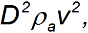
and the magnitude of the internal friction force — by the expression
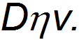
The ratio of these two expressions is precisely the Reynolds number:
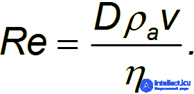
If we are not talking about the motion of a sphere, then by D is meant the characteristic size of the system (say, the diameter of a pipe in a problem about the flow of a liquid). From the very meaning of the Reynolds number it is clear that at its small values the internal friction forces dominate: the viscosity is large and we are dealing with laminar flow. At large values of the Reynolds number, on the contrary, the dynamic frontal drag forces dominate and the flow becomes turbulent.
The Reynolds number is of great importance in modeling real processes on smaller (laboratory) scales. If for two flows of different sizes the Reynolds numbers are the same, then such flows are similar, and the phenomena arising in them can be obtained one from the other by a simple change of scale of the coordinates and speeds measured. Therefore, for example, on a model of an aircraft or automobile in a wind tunnel one can predict and study the processes that will arise during real-world operation.
Drag coefficient. So, the drag coefficient in the formula for the drag force depends on the Reynolds number:
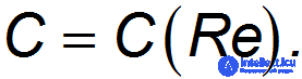
This dependence has a complex character, shown (for a sphere) in fig. 9.16. It is theoretically difficult to obtain this curve, and dependences measured experimentally for the given body are usually used. However, a qualitative interpretation of it is possible.
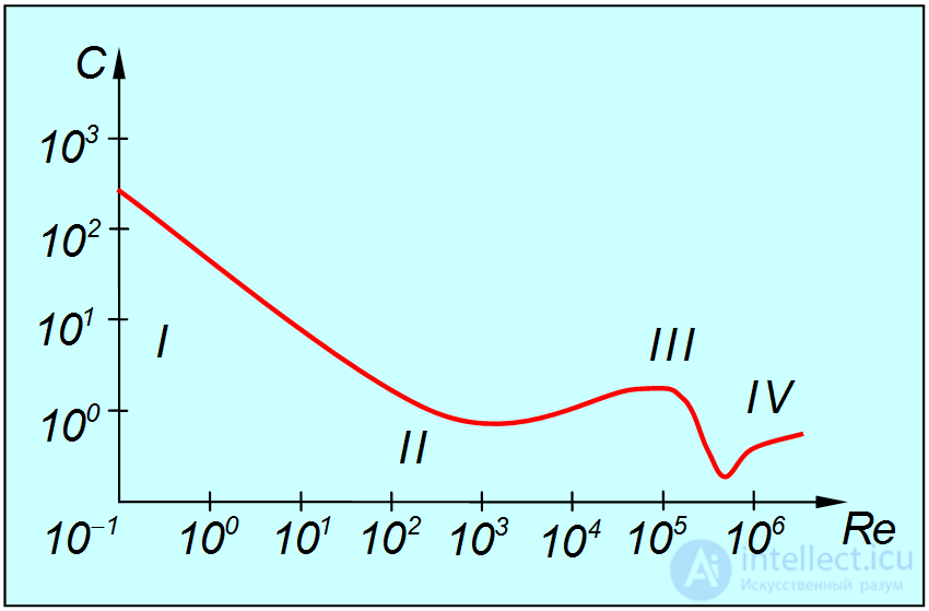
Fig. 9.16. Dependence of the drag coefficient on the Reynolds number (Roman numerals show the ranges of Re values corresponding to different flow regimes of the air stream)
Region I. Here the Reynolds number is very small ( < 1) and the flow of the stream is laminar. The experimental curve is described in this region by the function
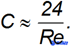
Substituting this value into the previously found formula for the drag force and using and the expression for the Reynolds number, we arrive at Stokes' law. In this region, as already said, resistance arises owing to the viscosity of the medium.
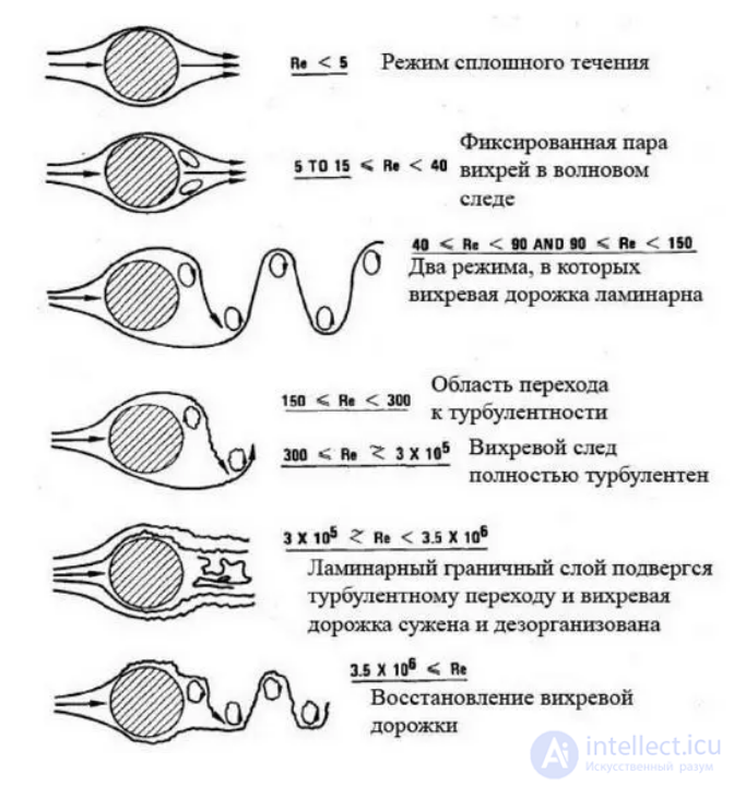
Region II. Here the Reynolds number lies in the interval 1 < < 2·104. This region corresponds to the transition from laminar to turbulent flow. Experimental data show that as the Reynolds number increases, some critical value is reached, after which the stationary laminar flow becomes unstable. Of course, this critical value is not universal and differs for different types of flows. But its characteristic magnitude is of the order of several tens.
At only slightly greater than the critical value, an unsteady periodic motion of the flow appears, characterized by a certain frequency. With a further increase in the periodic motion becomes more complex, and more and more new frequencies appear in it. These frequencies correspond to periodic motions (vortices) whose spatial scales become ever smaller. The motion acquires an increasingly complex and tangled character — turbulence develops. In this region the drag coefficient continues to fall as grows, but more slowly. A minimum is reached at = (4–5)·103, after which C rises somewhat.
Region III. This region corresponds to fully developed turbulent flow around a sphere, a regime we have already encountered above. The characteristic Reynolds number values here lie in the interval 2·104 < < 2·105.
While moving, the body leaves behind it a turbulent wake, beyond which the flow is laminar. A turbulent vortex wake can easily be observed, for example, behind a ship's stern. Part of the surface of the body adjoins directly the region of the turbulent wake, while its front part adjoins the region of laminar flow. The boundary between them on the surface of the body is called the separation line. The physical cause of the emergence of the drag force is the pressure difference between the front and rear surfaces of the body. It turns out that the position of the separation line is determined by the properties of the boundary layer and does not depend on the Reynolds number. Therefore the drag coefficient is approximately constant in this regime.
Region IV. However, such a flow regime around the body cannot be maintained up to arbitrarily large values of . At some point the front laminar boundary layer becomes turbulent, which pushes the separation line back. The turbulent wake behind the body narrows, which leads to a sharp (4–5-fold) drop in the resistance of the medium. This phenomenon, called the drag crisis, occurs in a narrow interval of values = (2–2.5)·105. Strictly speaking, the theoretical considerations given may change when the compressibility of the medium (air, in our case) is taken into account. However, this will manifest itself, as we have already discussed, at speeds of objects comparable to the speed of sound.
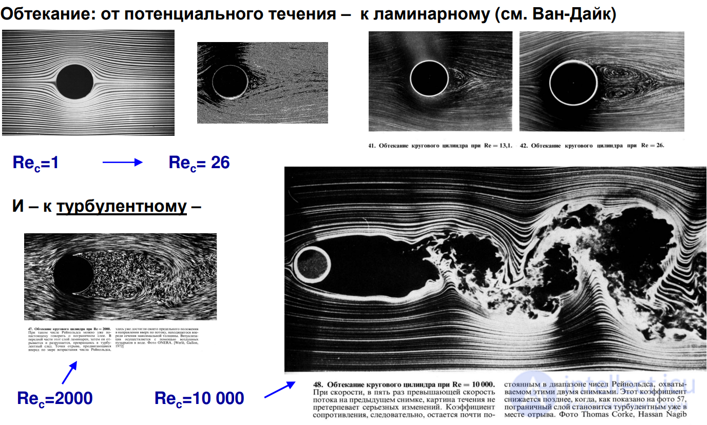
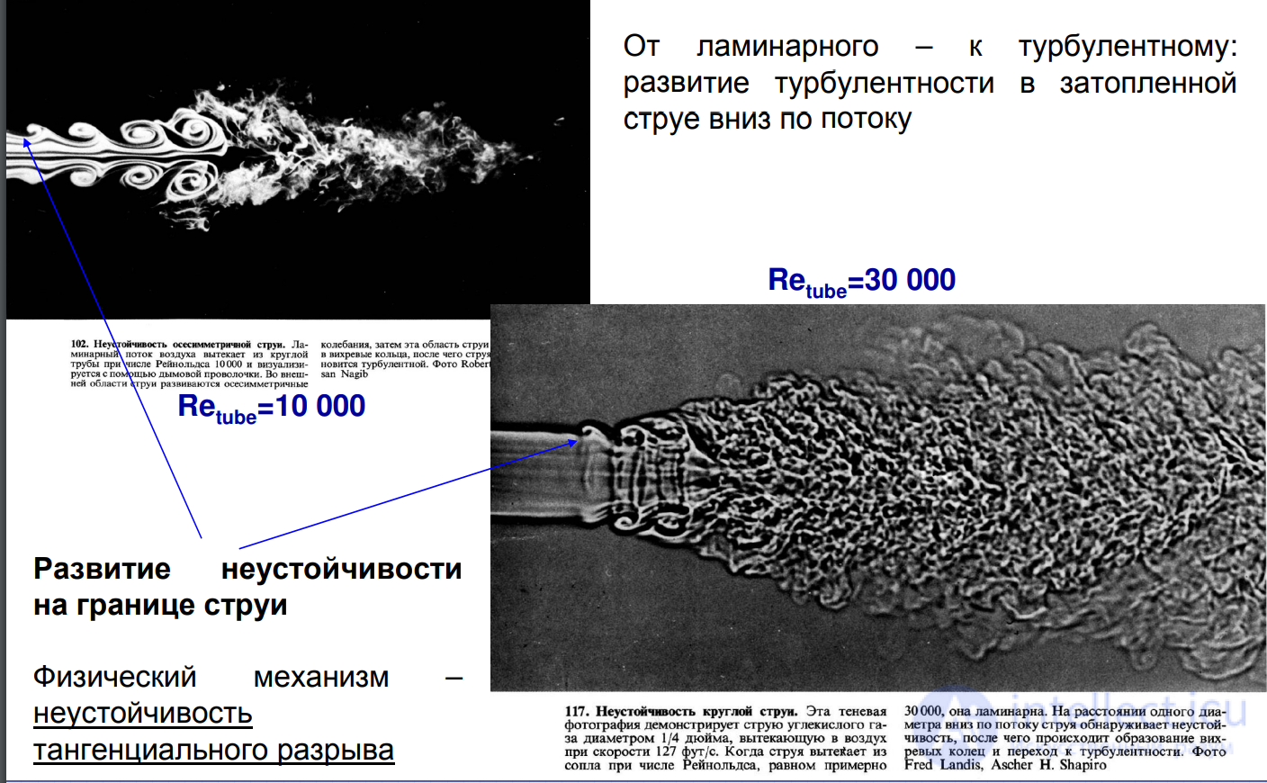
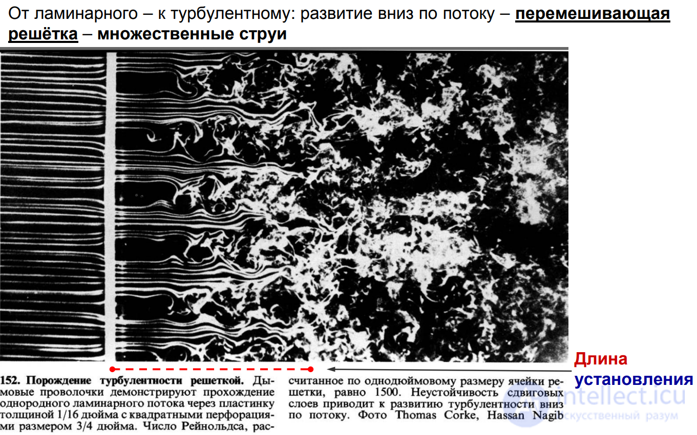
generation of turbulence by a grid
approaches to modeling turbulence
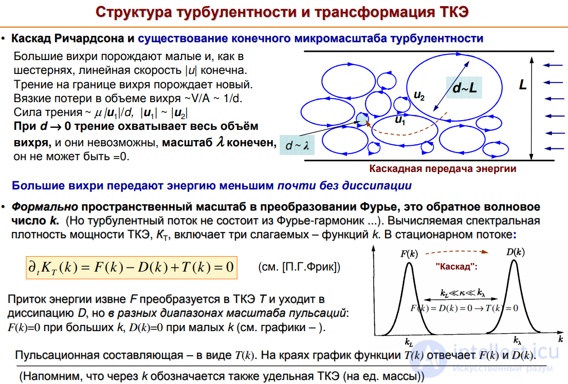
In fully developed turbulence: λ << lT<< L – the inertial interval is wide, and within it
all turbulence models "fit":
- RANS: flow cross-section scale ~L: the scale of energy "injection" into the flow;
- LES: down to scale lT: lT<< L (desirable); in fully developed turbulence lT>> λ;
- DNS: down to the microscale λ – all inhomogeneities of the flow
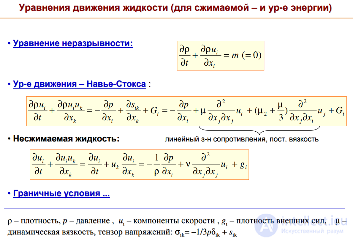
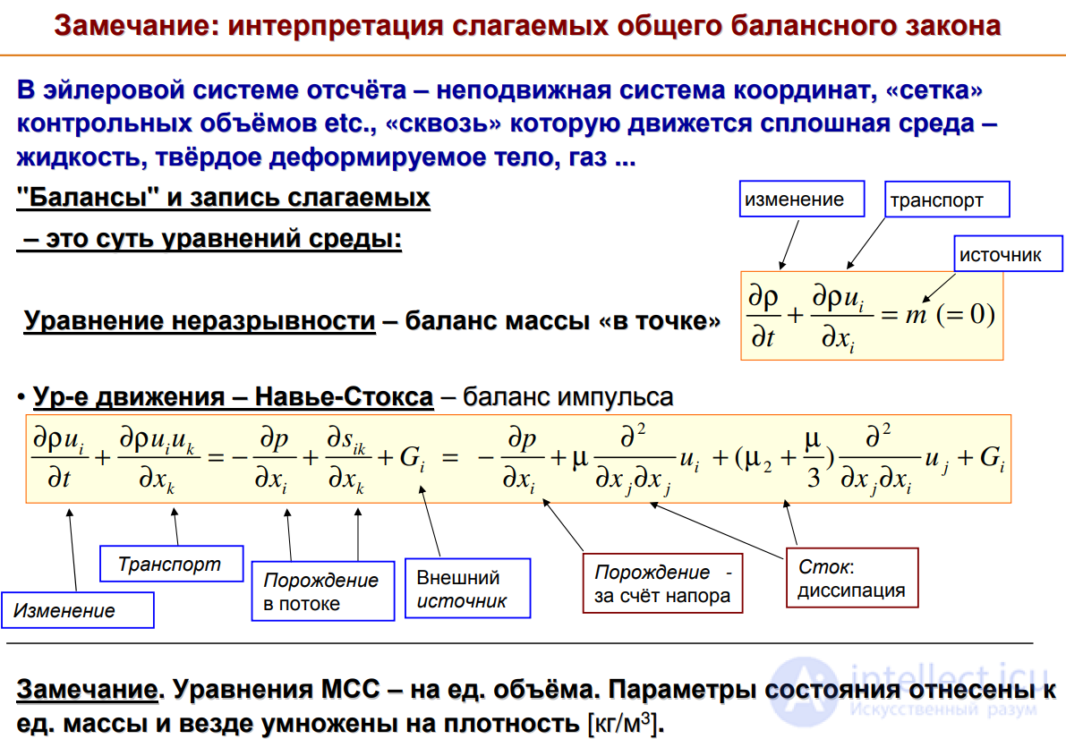
The Navier–Stokes equation describes the entire hydrodynamics of a Newtonian fluid, including the details of turbulent flow;
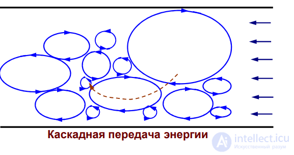
Cascade energy transfer used for modeling turbulence
RANS models based on the equation for turbulent kinetic energy (TKE)
0. TKE and its dissipation: they exist and are important for the description
1. Equation for TKE – derivation of the equation:〈equation for K〉 – equation for 〈K〉 = equation for 〈k 〉
2. Equations for TKE dissipation – introduction of the equation ...
3. Two-parameter turbulence models k-ε and k-ω

Comments