
Lecture
As already noted, Newton's laws hold only in inertial frames of reference.
Frames of reference moving with acceleration relative to an inertial frame of reference are called non-inertial.
In non-inertial frames of reference, Newton's first law does not hold. Everyone knows that when a bus jerks into motion, the passengers are pushed in the opposite direction. The bus is a non-inertial frame, and no visible action was exerted on the passengers by other bodies, yet they nevertheless did not remain at rest.
In principle, there is nothing forbidding the use of non-inertial frames of reference. We ourselves live in one — on the Earth, which rotates about its own axis and moves around the Sun. In such a frame of reference, the laws of dynamics look considerably more complicated. In essence, the dispute between the Ptolemaic and Copernican systems of the world concerned the question of which frame of reference to use: one tied to the Earth or to the Sun. The latter, as is well known, turned out to be far more convenient. The frame of reference tied to the Earth is non-inertial to a much greater degree, and in it the motions of the planets appeared complex and convoluted. But nothing forbids using a frame tied to the Earth either. One only has to correct the laws of dynamics accordingly.
Let us take an isolated body, not subject to the influence of other bodies. If we observe it from a non-inertial frame of reference, then, like the passengers on the bus, it will not remain at rest or move in a straight line at constant speed. And since its velocity changes, the body's acceleration is nonzero. This means that, multiplying the acceleration by the mass, we can use Newton's second law to find the force acting on the body. Forces of this kind are somewhat unusual in that we cannot point to the bodies responsible for them. Otherwise they are no different from the other forces we are already familiar with.
Forces acting on bodies in non-inertial frames of reference, and not due to the interaction of these bodies with other bodies, are called inertial forces.
Such forces are sometimes said to be fictitious, meaning by this that they would not exist in an inertial frame of reference. R. Feynman, in his “Feynman Lectures on Physics” (Moscow, “MIR”, 1967, page 225), calls them “pseudo-forces”.
This argument may seem not entirely convincing. What difference does it make if, in one frame of reference, a body has an acceleration (a force acts on it), while in another this acceleration is zero (there are no forces)? On passing from one frame of reference to another, the body's velocity and its energy change. After becoming acquainted with special relativity, we know that lengths and time intervals change as well. It is therefore natural to look at forces from this same point of view. So, inertial forces are quite real and can be measured, but they are observed only in non-inertial frames of reference. They are not a consequence of the interaction of the given body with other bodies; they are a consequence of the non-inertiality of the frame of reference. For one and the same body these forces are different and have different properties in different non-inertial frames of reference, depending on the nature of the motion of the non-inertial frame relative to the inertial one. However, as already stated, their manifestations are quite real and measurable.
Video 8.1. The “translational” inertial force: a still life with champagne
Video 8.2. The “translational” inertial force: an experiment with a weight on a cart
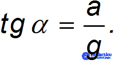
Consider a ball suspended on a thread, whose point of suspension 0' moves with acceleration a relative to some inertial frame of reference K. The suspension thread deflects from the vertical by some angle  . This angle is such that the resultant F of the thread's tension force T and the force of gravity mg causes the ball to move with acceleration a:

whence
This is how the phenomenon looks from the point of view of an observer in the inertial frame of reference K (fig. 8.1).
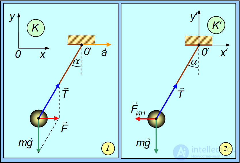
Fig. 8.1. Motion of a ball on a thread whose point of suspension moves with acceleration: 1 — from the point of view of an observer in the inertial frame of reference; 2 — from the point of view of an observer in the moving non-inertial frame of reference
Let us now attach the frame of reference K' to the point of suspension 0'. This frame will be non-inertial, since it moves with acceleration a relative to the inertial frame K. We are using non-relativistic mechanics, so the angle of deflection of the thread, as well as the forces T, mg, are the same for both observers. But for observer K' the ball is at rest (see fig. 1–2). On the other hand, observer K' sees that the resultant of the forces T and mg is not zero. Therefore observer K' concludes that in his frame of reference some force acts — an inertial force  , which did not exist in the inertial frame of reference K. We obtain the expression for the inertial force from the condition of equilibrium of the ball in the frame K', that is, from the sum of the three forces being zero:

Hence
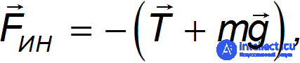
and from the equation of Newton's second law for the body, we obtain the expression for the inertial force in the translational motion of a non-inertial frame of reference with acceleration a:
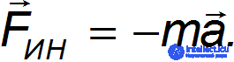
This same result holds in the general case for the arbitrary motion of a point particle in a non-inertial frame of reference K' moving translationally. Let its velocity of motion relative to the inertial frame of reference K be described by the function  , and let the axes of both frames remain parallel. Let the velocity of motion of the point particle in the frame K change according to the law
  . This means that in the inertial frame K, according to Newton's second law, the force acting on the point is

The velocity of this same point for the observer in the frame K' is equal to

This means that in the non-inertial frame of reference K' the force acting on the point is

Thus, in this case too, the inertial force is determined by the formula

where  — the acceleration of the translational motion of the non-inertial frame relative to the inertial one.
Video 8.3. A pendulum on a cart accelerating down an inclined plane
Note that, thanks to the equality of gravitational and inertial mass discussed in Chapter 5.4, an observer in the frame K' can assert that in his frame there is a uniform gravitational field, making bodies “fall” with acceleration
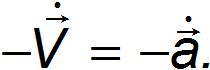
Einstein formulated the equivalence principle of non-inertial frames and gravitational fields, and on this basis built the general theory of relativity (GTR), or theory of gravitation.
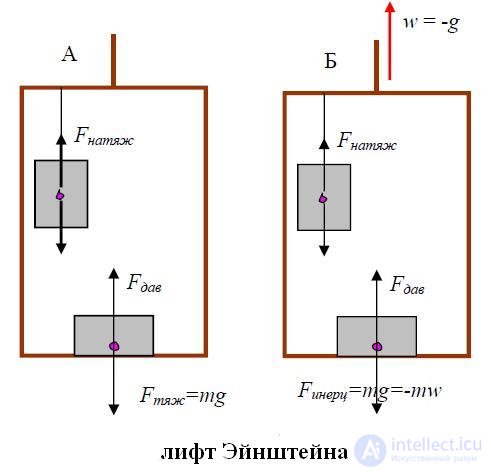
Fig. 8.2. Einstein's elevator
The appearance of an inertial force under accelerated translational motion of a frame of reference is demonstrated in the experiment shown in fig. 8.2.
Imagine a disk rotating uniformly with angular velocity  . Together with the disk rotates a ball mounted on a spoke, connected to the centre of the disk by a spring (fig. 8.3).
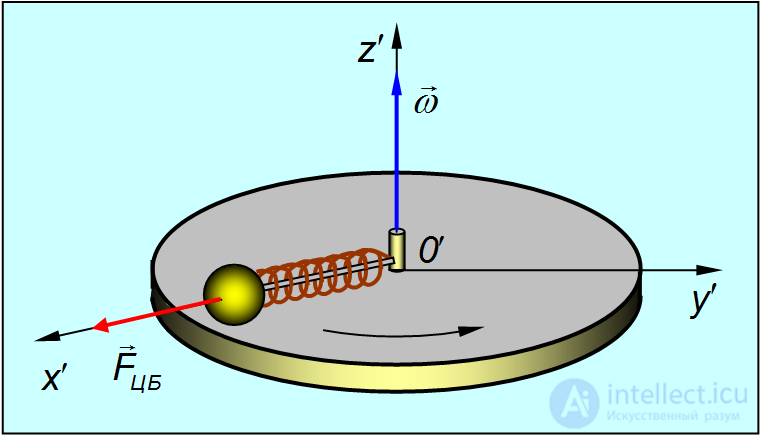
Fig. 8.3. The centrifugal inertial force in the frame of reference attached to the rotating disk
The ball is at rest relative to the disk and occupies a position on the spoke such that the tension force of the spring  turns out to be equal to the product of the mass of the ball
  and the normal (centripetal) acceleration (with uniform rotation of the disk, the tangential acceleration of the ball is, obviously, equal to zero)

where  — the position vector drawn to the ball from the centre of the disk (see fig. 8.3). But this is how an observer reasons who watches the rotation of the disk from an inertial frame of reference. Let us attach to the disk a rotating non-inertial frame of reference K', in which the disk together with the ball is at rest. The condition of equilibrium of the ball in this frame has the form:
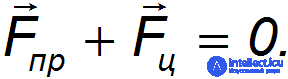
The observer in the rotating frame of reference explains the equilibrium of the ball by the presence of an inertial force

directed away from the centre of the disk 0' along the position vector .
The inertial force acting on a point particle in a frame of reference rotating uniformly with angular velocity ω is called the centrifugal inertial force:
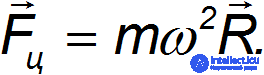
Here  — a vector drawn to the point particle from the axis of rotation, orthogonal to it. We introduced it in order to distinguish it from the position vector
  in the case where the origin of coordinates lies on the axis of rotation but not in the plane of rotation of the point particle.
Video 8.4. Centrifugal inertial force: suspended balls
For an arbitrary position of the origin on the axis of rotation, the position vector of some point particle can always be represented in the form

where par.— the component of the position vector parallel to the axis of rotation, and moreover lying on the axis of rotation (recall: the vector starts on the axis of rotation), while 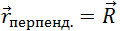 — its component perpendicular to the axis of rotation, starting on the axis of rotation, at the centre of the circle along which the point in question moves. Using the well-known formula

and taking into account that the vector product  and the scalar product
  are always equal to zero, one can show that the expression for the centrifugal inertial force is represented in the form

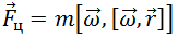
Thus, in the general case, for an arbitrary choice of origin on the axis of rotation, for any position of the point particle, the centrifugal inertial force acting on it can be written in the form
Video 8.5. The “astonishing” behaviour of a chain — here too the centrifugal inertial force is at work. The chain is light, with almost no friction between the links
Video 8.6. The “astonishing” behaviour of a chain 2. The chain is heavy, with large friction between the links
Example. A vessel with liquid rotates with angular velocity  about a vertical axis (fig. 8.4). Let us find the shape of the surface of the liquid.
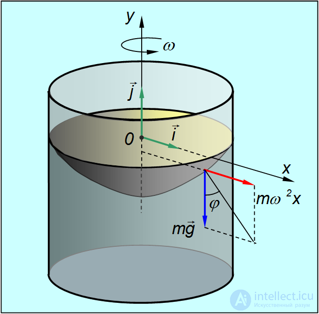
Fig. 8.4. Shape of the surface of a rotating liquid
We solve the problem in the frame of reference rotating together with the liquid. In this frame the liquid is stationary, but besides the force of gravity, the centrifugal inertial force also acts on it. The surface of the liquid is symmetric with respect to the axis of rotation. Consider the cross-section of this surface by some vertical plane containing the axis of rotation, which we take as the  axis.
axis.
Take an element of liquid on the surface of mass  , located at the point with coordinate
  . It is acted on by the force of gravity
 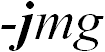 and the centrifugal inertial force
 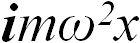 (here the coordinate
  is the distance from the axis of rotation, and
  and
and  — unit vectors). The resultant of these forces is inclined to the vertical at an angle
  such that
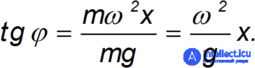
The surface of the liquid, described by the function  , is always positioned orthogonally to the line of action of the external forces. As is known, the tangent of the same angle can be found as the ratio of the increments
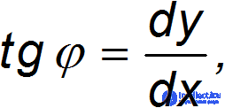
that is, as a derivative. We obtain the equation
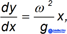
which is easily integrated:
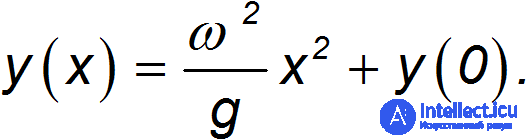
This equation, as is known, describes a parabola. Rotating this parabola defines a paraboloid of revolution. Thus, the surface of the rotating liquid takes the shape of a paraboloid of revolution. At 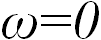 we have
 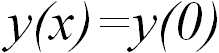 , that is, a flat horizontal surface.
Video 8.7. A circular “saw” made of paper – an unexpected application of the centrifugal inertial force
Video 8.8. The Coriolis force: the trajectory of a ball's motion on a rotating platform
In the previous section we considered a body at rest in a rotating frame of reference. If, in a rotating frame of reference, a body moves, then, in addition to the centrifugal force, one more inertial force will act on it, called the Coriolis force or the Coriolis inertial force.
Let a ball of mass  move without friction along the radius of a disk (fig. 8.5) with constant velocity
  , directed toward a certain point
  at the edge of the disk.
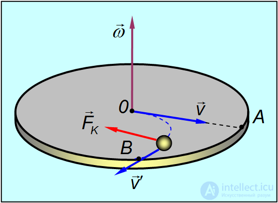
Fig. 8.5. Deflection of a ball moving in a rotating frame of reference
If the disk is not rotating, the ball moves along the radius and reaches point  . If, however, the disk is set into rotation with angular velocity
  , then by the time the ball reaches the edge of the disk, the place of point
  will be occupied by a different point
  . If the ball leaves a trace, it will trace out its trajectory relative to the disk — a curved line
  . In doing so, no visible forces act on the ball, and relative to the inertial frame it still moves with constant velocity
  . But the velocity of the ball relative to the disk
  did change its direction. This means that, in the frame of reference attached to the rotating disk, an inertial force not parallel to the velocity
  acted on the ball. Consequently, it was not directed along the radius, from which it follows that this force differs from the centrifugal inertial force considered above. It is called the Coriolis force.
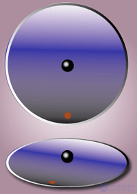
Fig. 8.6 Motion of a ball on the smooth surface of a rotating disk. Top — from the point of view of an outside observer. Bottom — from the point of view of an observer stationary relative to the disk
Let us find the expression for the Coriolis force in the particular case (fig. 8.7) where a particle of mass  moves relative to the rotating frame of reference K' uniformly along a circle lying in a plane perpendicular to the axis of rotation
  , with its centre on the axis of rotation.
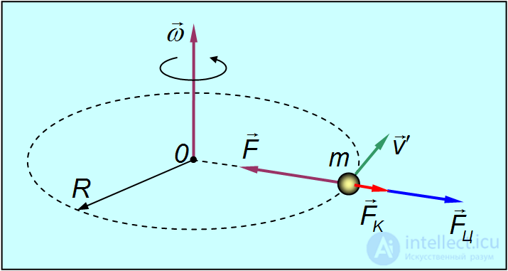
Fig. 8.7. Toward deriving the expression for the Coriolis force
Let us denote the velocity of the particle relative to the rotating frame K' by  . In the fixed (inertial) frame of reference K, the particle also moves along a circle, but its linear velocity equals

where  — the angular velocity of the rotating frame,
  — the radius of the circle. For the particle to move relative to the fixed frame of reference K along a circle with velocity
  , a force
  directed toward the centre of the circle must act on it (for example, the tension of a thread), and the magnitude of this force equals

Relative to the rotating frame of reference K', in this case, the particle moves with acceleration
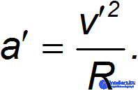
From the equation of Newton's second law obtained above for the particle, we get:
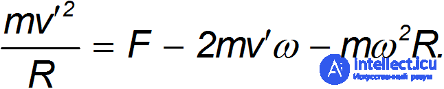
On the left stands the product of the mass and the acceleration of the particle in the rotating frame of reference. This means that on the right must stand the forces acting on it. The first term is clear: this is the tension force of the thread, which is the same for both the inertial and the non-inertial frames. We have also already dealt with the third term: this is the centrifugal inertial force, directed along the radius (away from the centre). The second term is precisely the Coriolis force. In this case it is likewise directed away from the centre, but it depends on the velocity of the particle. The magnitude of the Coriolis force in this example equals 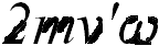 . Its direction coincides with the motion of a corkscrew whose handle turns from the velocity vector
  toward the angular velocity vector
  .
.
It can be shown that in the general case the Coriolis force is defined as
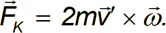
The Coriolis force is orthogonal to the velocity vector. In the case of the radial motion shown in fig. 8.5, it deflected the ball to the right, forcing it to move along the trajectory  .
.
The appearance of the Coriolis force in the motion of a body relative to a rotating frame of reference is demonstrated in the experiment in fig. 8.6.
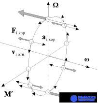
The Coriolis force acts only on bodies moving relative to a rotating frame of reference, for example, relative to the Earth. Let us give some examples.
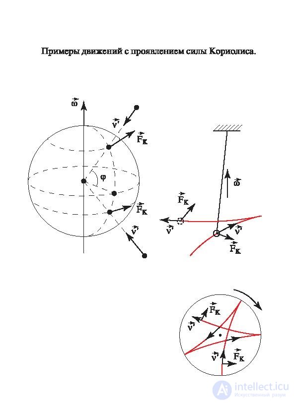
Fig. 8.8. The Coriolis force on the surface of the Earth
In the Northern Hemisphere, stronger erosion of the right banks of rivers is observed, the right rails of railway tracks (in the direction of travel) wear faster than the left ones, and cyclones rotate clockwise. In the Southern Hemisphere, everything happens the other way around.
When firing a gun aimed north, the shell will deflect to the east in the Northern Hemisphere and to the west in the Southern Hemisphere (fig. 8.9).
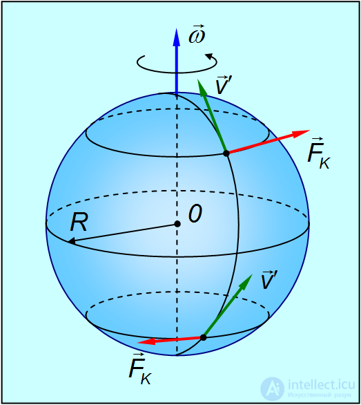
Fig. 8.9. On Earth, moving bodies deflect to the right in the Northern Hemisphere and to the left in the Southern Hemisphere
When firing along the equator, the Coriolis force will press the shell toward the ground if the shot is fired to the west, and lift it upward if the shot is fired in the eastern direction.
Video 8.9. The Coriolis force: try to hit it! Shooting on a rotating platform.
Example. A train of mass  = 150 tonnes travels in the meridional direction to the north with speed
  = 72 km/h. Let us find the Coriolis force pressing it sideways against the rails, and determine what the effect of the centrifugal force is. The train is located at the latitude of Moscow
  = 56°.
The angle between the vector of the angular velocity of the Earth's daily rotation and the tangent to the meridian equals the latitude of the place (fig. 8.10).
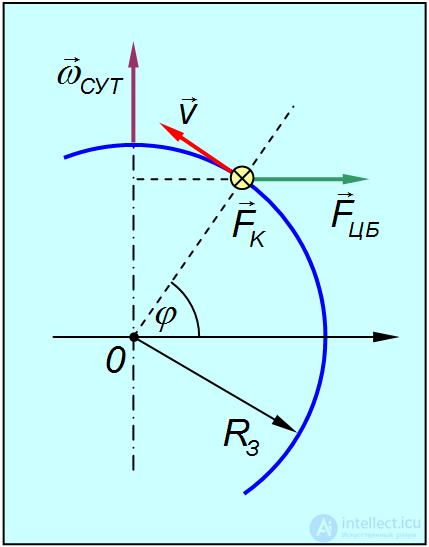
Fig. 8.10. The Coriolis force is directed away from us, perpendicular to the plane of the figure
Therefore the Coriolis force equals

Substituting the numerical data, we find

This force corresponds to the weight of a mass
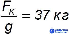
and amounts to 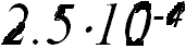 of the weight of the train.
The distance of the train from the Earth's axis of rotation equals 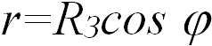 , so the centrifugal force will be

It is directed perpendicular to the axis of rotation. Consequently, its component

directed along the radius of the Earth, decreases the weight of the train:

Substituting the numerical data, we obtain

This corresponds to the weight of a mass
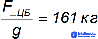
and amounts to 1.1·10–3 of the weight of the train.
The other component of the centrifugal force
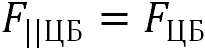
is directed along the tangent to the meridian and decelerates the train. It equals

which corresponds to the weight of a mass
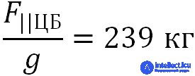
and amounts to 1.6·10–3 of the weight of the train.
Thus, the influence of the centrifugal force manifests itself in tenths of a percent, while the manifestations of the Coriolis force are an order of magnitude smaller (which is of course connected with the low speed of the train).
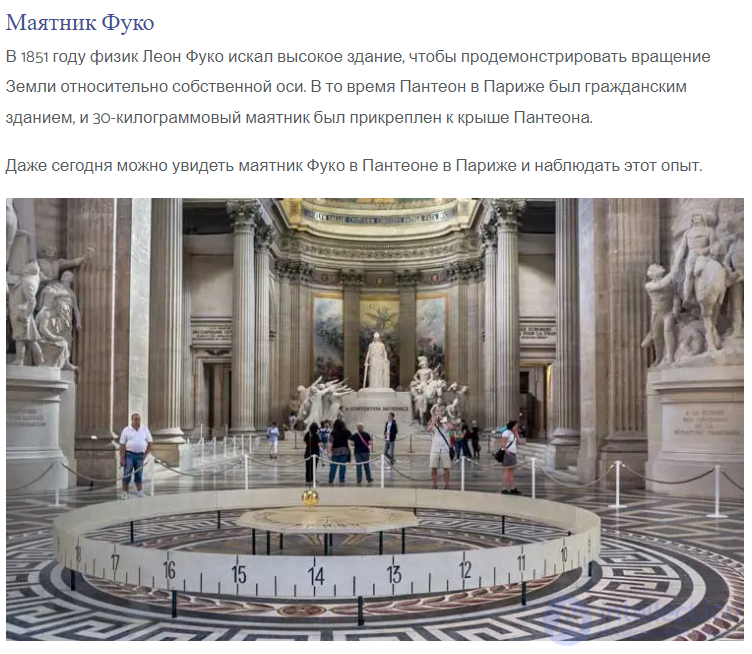
The French physicist Foucault experimentally proved the rotation of the Earth about its own axis using a 67-metre pendulum suspended from the top of the dome of the Panthéon in Paris. A similar pendulum could until recently be seen in St. Petersburg, in St. Isaac's Cathedral.
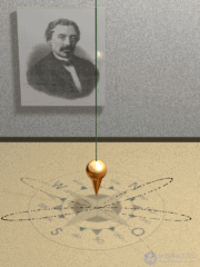
Fig. 8.11. The Foucault pendulum
The oscillations of the Foucault pendulum depend on how they were excited. If the pendulum is deflected to the maximum angle and then released without initial velocity, the pendulum will oscillate as shown in fig. 10. The speed of the pendulum at the position of maximum deflection will be zero.
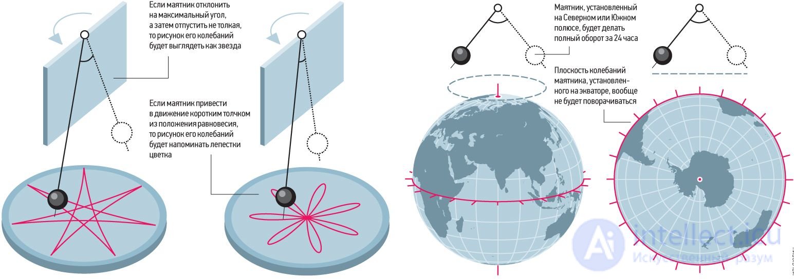
Fig. 8.12. Oscillations of the Foucault pendulum when deflected to the maximum angle and released without initial velocity
Fig. 8.13. Oscillations of the Foucault pendulum when given velocity while deflected to the maximum angle
A somewhat different character of the trajectory results if the pendulum is set in motion by a short push from the equilibrium position. This case corresponds to fig. 8.11. and 8.13. The speed of the pendulum at the position of maximum deflection corresponds to the speed of rotation of the Earth at the latitude of observation.

Comments