
Lecture
The specific character of flight activity is, first and foremost, determined by the pilot's separation from the ground, which accounts for the exceptional unusualness and complexity of this professional
activity. Piloting an aircraft involves new degrees of freedom of movement in space, rapidity and dynamism of events, their non-repeatability, noise, vibration, and accelerations of considerable intensity, duration, and direction.
The piloting process involves the perception of instrument (panel) and non-instrument (out-of-cockpit information, angular and linear accelerations, forces on the controls) information, the formation, on this basis and on the basis of knowledge,
memory, and thinking, of a mental image of the flight, and the motor implementation of actions aimed at
changing (or maintaining) the corresponding flight mode. The pilot's activity is combined in nature (aircraft control, flight and navigational
orientation, out-of-cockpit observation) and is characterized by a high degree of uncertainty. The pilot is required to bear a high degree of responsibility for the fate of the passengers, crew
members, cargo being transported, the aircraft itself, and himself.
In order to form a complete picture of the specific character of a pilot's activity, let us examine
in detail the above-listed components of professional activity. A pilot's professional activity is built on the basis of information arriving through the sense
organs (analyzers), and the state of the latter largely determines the reliability of the pilot as an
operator. In flight, the analyzer systems often work at or beyond the limits of their
capabilities, which places heightened demands on the pilot's physiological systems.
Analyzers (Gr. analysis – breakdown, decomposition) are a complex of anatomical structures
that perceive the energy of an external stimulus, convert it into a nerve impulse, and
transmit it to the corresponding parts of the brain. Each analyzer consists of three parts:
- a peripheral part, which perceives the stimulus and converts it into a
nerve impulse;
- a conducting pathway, along which the nerve impulse travels to the nerve center;
- the cortical end of the analyzer, located in the corresponding areas of the cerebral
cortex.
Each analyzer gives rise to sensations peculiar to it alone (sensations of a single modality). A sensation is the reflection of individual properties of objects during their direct
action on the sense organs. Sensations arise as images reflecting individual
properties of objects. Monomodality (Gr. monos – one + Lat. modus – inflection, measure,
manner) distinguishes sensation from the higher form of sensory reflection – perception,
which is polymodal, arising as a result of the combined work of several analyzers.
Among the psychophysiological factors underlying aviation accidents,
a significant number are related to visual function disorders (errors of depth
perception, visual illusions, being «blinded» on landing by the light screen produced by turning on
the landing lights). It should be noted that a person receives about
90% of information through the visual organs.
The peripheral part of the visual analyzer is represented by the eyeball, covered by the fibrous (albuginea), vascular, and photosensitive coats (Fig. 2.1). The
outermost coat of the eyeball is the fibrous coat (Lat. fibra – fiber), which
is subdivided into the transparent anterior part, called the cornea, and the opaque posterior part – the sclera (Lat. sklera – tough, hard). Beneath the fibrous coat lies
the vascular coat; it is divided into three parts: the choroid proper, the ciliary body,
and the iris. The choroid proper performs a trophic (Gr. trophe – nutrition) function, that is, it nourishes the eye. The ciliary body participates in the accommodation of the eye (the eye's ability to see equally well objects located at various distances), fixing the lens in a certain position. Anteriorly, the ciliary body
continues into the iris, which is a round disc with an opening in its
center – the pupil. The iris is located between the cornea and the lens.
The photosensitive coat, or retina (Fig. 2.1, 2.2), of the eyeball contains
photoreceptor (Gr. photos – light + Lat. recipere – to receive) cells – rods and cones,
which are responsible for the perception of objects in darkness and in light, respectively. Several layers are distinguished in the retina (Histology…, 2001).
1. The pigment (Lat. pigmentum – coloring substance) layer – contains cells of polygonal (multi-angled) shape, adjacent on one side to the choroid and, on the other, to the photoreceptor cells – rods and cones (Fig. 2.2). The cells of this layer (pigment epithelium cells) store vitamin A, participate in its
conversions, and pass its derivatives to the photoreceptors for the formation of visual pigment.
2. The outer nuclear layer – includes the nucleus-containing parts of the photoreceptor cells. Photoreceptor cells contain visual pigments: rhodopsin – in rods, and red, green, and blue pigments – in cones. Corresponding to the three types of pigment (red, green, blue), three types of cones are distinguished: the spectral sensitivity of the red, green, and blue pigments corresponds to 560, 535, and 440 nm,
respectively. [Vision under ordinary conditions is normally trichromatic; however, in some people one of the cone types has pathologically low sensitivity. Such people are called color-anomalous. A person who
perceives colors with two types of cones is called a dichromat. Depending on which
particular color is not perceived, dichromats are divided into: those who do not perceive red
– protanopes, those who do not perceive green – deuteranopes, and those who do not perceive blue – tritanopes. People who do not perceive color at all are called monochromats (Volkov V.V., 1989)].
3. The outer plexiform layer – in it the inner segments of the rods and cones contact the dendrites of bipolar (two-process) cells.
4. The inner nuclear layer – contains horizontal cells (which receive information from
cones and also transmit it to cones), amacrine cells, and bipolar cells
connecting rods and cones to ganglion cells.
5. The inner plexiform layer – in it bipolar cells make contact with ganglion cells,
while amacrine cells act as interneurons.
6. The ganglion (Gr. ganglion – subcutaneous tumor) layer – contains ganglion cells
– multipolar (Lat. multum – many + Gr. polos – earthly and celestial axis), or multi-process, neurons, the long processes of which (axons) form the optic
nerve.
Horizontal, amacrine, bipolar, and ganglion cells are neurons, while
Müller cells belong to the neuroglial cells (auxiliary cells of the nervous
system that perform homeostatic, nutritive, or supportive functions). The outer
processes of Müller cells end in microvilli, while the inner ones have
an expansion (foot process) at the border with the vitreous body (Fig. 2.2). These glial cells
maintain the ionic homeostasis of the retina: in particular, they reduce the concentration of potassium ions
in the extracellular space, where their concentration rises sharply under light stimulation. They capture potassium ions from the outer layers of the retina and direct them through
their foot process into the fluid of the vitreous body.
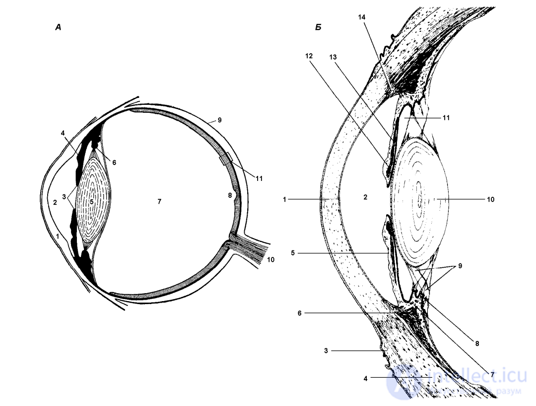
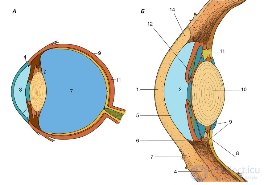
Fig. 2.1. Structure of the eyeball (A) and its anterior segment (B)
A (after: Korobkov A.V., Bashkirov A.A., Vetchinkina K.T., 1980): 1 – cornea; 2 – anterior chamber; 3 – pupil; 4
– iris; 5 – lens; 6 – ciliary muscle; 7 – vitreous body; 8 – central fovea on the retina; 9 – sclera; 10 – optic nerve; 11 – area of the retina (shown enlarged
in Fig. 2.2). B (after: Histology…, 2001): 1 – cornea; 2 – anterior chamber; 3 – conjunctiva; 4 –
sclera; 5 – iris; 6 – ciliary muscle; 7 – ciliary body (an expansion of the choroid, consisting of ciliary processes and the ciliary ring, inside which the ciliary muscle is located); 8 – ciliary process (ciliary processes are radial
folds containing a large number of capillaries; the epithelium covering the processes produces
aqueous humor, which first enters the spaces of the ciliary zonule, communicating with the posterior
chamber, and then, through the pupil, into the anterior chamber); 9 – ciliary zonule – the suspensory apparatus of the lens, consisting of radially oriented fibers separated by slit-like spaces;
10 – lens; 11 – posterior chamber; 12 – pupillary sphincter (a network of spiral muscle fibers innervated by parasympathetic fibers of the oculomotor nerve and causing constriction of the pupil); 13 –
pupillary dilator (a thin layer of muscle fibers, most of which are oriented radially; innervated by sympathetic fibers from the internal carotid plexus); 14 – venous sinus
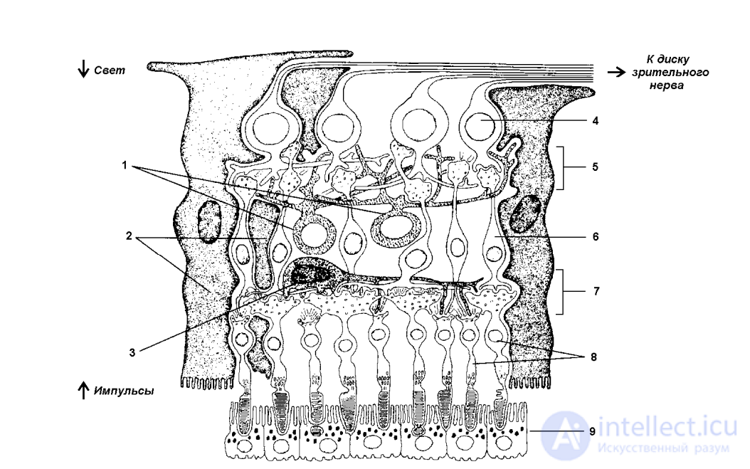
Fig. 2.2. Structure of the retina
(after: Histology…, 2001)
The pigment epithelium surrounds the outer segments of the photoreceptor cells, which form synaptic
contacts with bipolar neurons. Information from bipolar cells is transmitted to ganglion cells
and travels along their axons, which form the optic nerve, into the brain. 1 – amacrine cells; 2 – Müller cells; 3 – horizontal cell; 4 – ganglion cell; 5 – inner plexiform layer; 6 –
bipolar cell; 7 – outer plexiform layer; 8 – photoreceptor cells; 9 – pigment epithelium
The site of best vision on the retina is the central fovea (see Fig. 2.1) – a depression in the middle part of the macula lutea (about 2 mm in diameter) – here there are no rods, but
a great many cones (up to 100,000 per 1 mm2
). The point at which the optic nerve leaves the retina
is called the optic disc, or blind spot (no image is formed here at all). The pathway of the visual analyzer begins with the optic nerve and ends in the visual areas of the cerebral cortex.
By the nature of their profession, pilots need not only impeccable vision but also the ability to accurately judge the distance to objects outside the cockpit (above all, to the
runway), which constitutes the essence of an ability known as «dynamic depth perception».
In flight, a pilot judges distances by the angular size of visible objects, by objects appearing before or disappearing from view, and by the speed with which
ground landmarks move. Distance perception is not an innate property but a trainable one, based on the formation of conditioned reflexes. A cadet acquires the ability to correctly judge flight altitude
first in flights with an instructor, and subsequently on his own. Using out-of-cockpit landmarks, the cadet takes up the required altitude and checks it against the instruments.
In this process, conditioned-reflex associations are formed – dependencies between altimeter readings, the angular size, and the speed of movement of ground landmarks.
Once these dependencies are sufficiently well established, the pilot judges altitude from the angular size
of already familiar objects, rarely resorting to instrument readings. In such cases the errors do not
exceed 10% (Litvinchuk N., Kozlov V., 1982). As the authors point out, good results are already achieved by the third flight, after solving 12–15 individual tasks in each of
them. When a pilot flies over unfamiliar terrain, errors in the visual determination of altitude, as a rule, amount to up to 30% of the true value. The reason for this is the absence
of objects familiar to the eye by which the distance to the ground could be accurately judged.
The same holds true for flights over featureless terrain (desert,
water surface, snow-covered field) and after lengthy breaks in flying duty.
Special demands on the accuracy of judging distance to the ground arise on landing. In
the process of the aircraft's descent along the glide path, the altitude, airspeed, and the
picture of the earth's surface change intensively. The flare-out and the smooth touchdown of the aircraft depend directly on the accuracy of judging the distance to the ground and on the control-surface actions taken. On landing, the pilot judges the absolute distance to the ground and the rate of its change from the angular velocity of the ground surface's movement and the apparent size of ground objects.
The pilot monitors the decrease in altitude by the increase in angular velocity and increase in the angular size of objects, and by the improvement in the visibility of details of the earth's surface. In this connection,
the choice of the optimal direction of gaze at the ground is of fundamental importance.
It has been established that the most favorable direction of gaze for perceiving a change in altitude is one in which the apparent rate of movement of the earth's surface is greatest. A departure from the habitual direction of gaze entails a change in the angular
velocity of the movement of ground objects and the appearance of errors such as flaring too high or too low,
landing at excessive or insufficient speed, and inconsistency of landings. In order to
minimize these errors, it is necessary that the pilot's seat always occupy one and the same
position (height), and that the gaze on landing be fixed at one and the same angle. Experienced pilots can distinguish, during the flare, deviations in altitude of about 10 cm (Litvinchuk N., Kozlov V., 1982).
The type of aircraft has a serious effect on the pilot's judgment of altitude above the ground.
Thus, on the An-124 aircraft, owing to the high position of the pilot's eye level when performing
a landing at night, as well as in fog, rain, or snowfall, when the probability of visual illusions increases, it is very difficult (and more often impossible) to correctly
judge the distance to the ground (Tsibulkin V.A., 2008). Fig. 2.3 shows the difference between the
altitude determined visually and by the radio altimeter, which measures altitude relative to
the lowest point of the main landing-gear wheels.
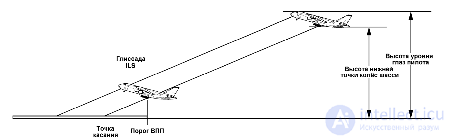
Fig. 2.3. The relationship between the height of the pilot's eye level and the height of the lowest point of
the landing-gear wheels on the An-124 aircraft (after: Tsibulkin V.A., 2008)
While in the aircraft's cockpit, the pilot cannot see part of the space outside the cockpit, since
it is obscured by the nose of the fuselage. If, under level-flight conditions, a line is drawn from the
pilot's eyes tangent to the aircraft's nose, it forms an angle with the horizon,
which determines the downward field of view from the cockpit (Fig. 2.4). The area not falling within the
field of view is determined from the trigonometric relationship between the aircraft's flight altitude and
the viewing angle. Thus, an aircraft nose with a viewing angle of 15° at an altitude of 50 meters above the earth's surface obscures approximately 185 meters. Consequently, at a visibility of 500 meters, the pilot will be able to see a zone extending approximately 300 meters ahead of the aircraft. The aircraft's pitch
angle when gliding at high angles of attack can reduce
this zone even further (see Fig. 2.4).
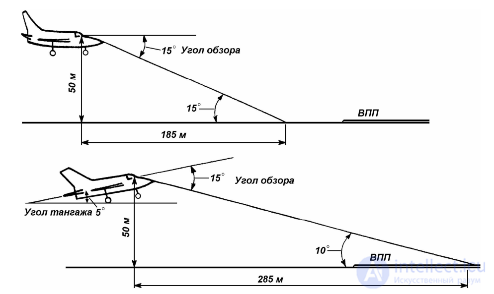
Fig. 2.4. Influence of the viewing angle and pitch angle on the reduction of the zone of visible
ground landmarks (after: Manucharov A., 1974, a)
Depth perception is also influenced by so-called aerial perspective
(Platonov K.K., Schwartz L.M., 1948): light rays reflected by nearer objects are absorbed by the air to a lesser degree than rays reflected by more distant objects, which
also contributes to the perception of depth; in clear weather, when the air is transparent, distant objects appear closer, whereas in hazy weather they appear more distant.
Eye movements and the perception of distance to the ground during the flare depend on the speed
of visual perception. According to data from V.V. Goryansky (1951), a visual perception speed of 0.1–0.4 s was observed in 34% of cadets falling behind in flight training, and in only
9% of those succeeding; a visual perception speed of 0.01–0.005 s was observed in 35% of successful cadets and 68% of unsuccessful ones. In the course of flight training the speed of visual perception increases, amounting for jet fighter pilots
significantly more often to 0.006–0.01 s than to 0.01–0.02 s (Baranovsky V.V., Shigimaga Yu.S., 1952).
The perception of altitude is also influenced by the rate of flicker of the ground. On landing in
calm-wind conditions, when the aircraft's true speed during the flare is greater than usual with moderate wind (and, consequently, the ground flickers faster), an illusion of a more
rapid approach to the ground arises (Platonov K.K., Schwartz L.M., 1948), for which reason it is necessary
to teach the pilot to judge altitude not only by the «running of the ground», but also by the perceived duration
of the flare and by the forces on the control column (Platonov K.K., Goldstein B.M., 1972). In this connection,
a common error is flaring too high, although sometimes a cadet, having flared the aircraft too high several times, overcompensates and instead begins to «press» the aircraft
toward the ground, as a result of which he sets it down on the wheels. This same error can also recur when transitioning to higher-speed aircraft.
The question under consideration – assessing flight altitude as a function of the angular velocity
of the ground's approach ω – was later analyzed by N.
Litvinchuk (1984), a first-class military flight instructor. The angular velocity of the ground's approach ω depends on the ground speed Vk and
the height of the pilot's eyes above the earth's surface h. A discrepancy between the actual ground
speed and the speed at which the skill of judging altitude was developed leads to distortions in
its perception, owing to a change in ω at the computed altitude. Since the angular velocity of the ground's approach
is tied to the earth-fixed coordinate system, while piloting is carried out relative to
airspeed (indicated speed), a change in air density, as well as wind, will affect the judgment of distance to the ground. If the skill was acquired in calm-wind conditions with an indicated airspeed of
300 km/h and h = 3.5 m (the height at the end of the flare H1 = 1 m), then with a headwind of 10 m/s
the pilot will tend to complete the flare at h = 3.08 m (H1 = 0.58 m), while with a tailwind
of 10 m/s – at h = 3.92 m (H1 = 1.42 m). As N. Litvinchuk (1984) points out, the simplest way to eliminate perceptual errors in the presence of a headwind is to bring the aircraft to the start of the flare with an excess speed equal to the wind speed at the given altitude.
Visual perception of the space outside the cockpit becomes significantly more difficult on an approach
to landing in diffuse cloud with an uneven lower base, in thick haze with variable
visibility, or in broken cloud of varying altitude and density – that is, under what the Honored Test Pilot of the USSR A. Manucharov (1974, a) termed indeterminate
weather conditions.
In diffuse cloud with an indeterminate lower base, or in broken cloud
of variable altitude accompanied by haze and poor visibility, especially in winter,
when the ground is covered with snow, as well as in featureless and visually cluttered terrain, control landmarks usually have no clear outlines. They are hard to detect and easily lost. Timely determination of the aircraft's spatial position relative to
the runway is difficult under such conditions. To successfully perform a landing at minimum weather conditions, careful flight preparation is required: weather conditions must be taken into account, along with the approach lighting system, runway markings, characteristic visual landmarks and their probable visibility, and coordination of the crew members' actions must be ensured.
Detailed flight preparation and a clear understanding of the influence of weather conditions on the use of visual landmarks are of decisive importance in transitioning from instrument to visual piloting. As A. Manucharov (1974, a) points out, a widespread method
of transitioning from instrument to visual piloting is to switch the pilot's attention
to ground landmarks only after fully breaking out of the clouds, but
this method is no longer suitable in cases where, for example, because of low remaining fuel it is impossible to divert to an alternate airfield and the landing must be made in any event, and a «full breakout» from the clouds does not occur virtually until the altitude at which the flare begins (at best – until the decision altitude). Here reference is made to the minimum safe altitude,
established for each type of aircraft at a given airfield, at which the pilot decides whether to land or go around. In this case the only acceptable option may be a mixed method of piloting – instrument and visual. This method, as the author notes, is applicable both by day and by night. It provides for
the gradual incorporation of visual landmarks, as they appear, into the cross-check scheme used during instrument piloting.
A pilot performing an approach to landing under indeterminate weather conditions, passing through
diffuse cloud, may fail to see the approach lights or the runway. It is
very important for the pilot to know the distance from which he can distinguish visual landmarks for
lining up with the runway. The visibility stated in a weather report may prove to be overestimated, not corresponding to the slant range at which the pilot actually
sees the runway. A. Manucharov (1974, a) stresses that one must be prepared for this and bear in mind that the difference between forecast and actual visibility can amount to several hundred meters. In a number of cases, diffuse clouds merge with broken fog,
through which light landmarks can be seen. The zone of visibility in such cases often
changes substantially during the course of the approach, and the pilot may be misinformed if the weather report contains data obtained in a zone of relatively good visibility. Under such weather conditions the danger lies in a satisfactory visibility of landmarks at the beginning of the approach, followed by its deterioration. At the start of an approach the pilot may see the approach lights and, possibly, even partially see the runway
landmarks. However, upon entering an area of broken fog, most of the landmarks
(or all of them) may suddenly be lost. If the piloting is not being conducted by instruments and the pilot is not psychologically prepared for a deterioration in visibility, he may lose spatial orientation. The flight should be conducted by instruments until the
visual landmarks become clearly distinguishable. Correcting the aircraft's position relative to the runway can be done only once a sufficient number of landmarks become distinguishable.
It cannot be ruled out that a pilot in very difficult weather conditions will not see any landmarks throughout the entire approach and will see only the last 500 meters of the approach lighting system.
It is necessary to know the approach lighting system well in order to quickly and correctly form a
picture of the relative arrangement of the landmarks and the runway. In preparing for a flight,
the crew is obliged to work out a backup plan in case the weather conditions turn out to be worse than the established minimum for the pilot. On an approach to landing in cloud with a raised
fog base of 50–100 m, one can count on good visibility after breaking through it, since such
fog forms a more or less clearly defined lower base. Therefore, the transition from instrument flight to visual flight will require, after breaking out of
the cloud, a rapid switch of attention to visual landmarks. On an approach under these conditions at night, upon emerging below the clouds, it may seem that the aircraft is
at a greater altitude than it actually is. In this case the pilot must continue the flight by instruments, cross-checking the position against visual landmarks (Manucharov A.,
1974, a).
An unexpected encounter with heavy rain after switching to visual flight can create a very difficult situation, since in heavy rain visual landmarks are poorly
discernible and may be lost entirely. An approach to landing at night during rain is further complicated by the fact that the pilot may be blinded by strobe lights or runway threshold lights, repeatedly reflected and refracted by drops of water on the windshield. Heavy rain, with insufficiently effective windshield wipers, can flood the windshield and obscure landmarks at
the moment of transition to visual flight. In snowfall and blizzard conditions, visibility can vary
over a very wide range, creating completely indeterminate conditions. Identification of the runway during the visual segment of the approach under these conditions is further hampered by landmarks being drifted over with snow. The pilot has some possibility of orienting by the
approach lights and runway lights, whereas the runway markings
and the contrast between the runway and the surrounding terrain are lost in the whiteness of the snow.
It should be remembered that in poor visibility, the number of landmarks helping the pilot
to correct the aircraft's position relative to the runway is substantially fewer than under
simple weather conditions (Manucharov A., 1974, a).
According to A. Manucharov (1974, b), it is more correct for the copilot to perform the
approach on instruments (maintaining heading and glide path) until reaching the commander's established weather minimum altitude. At the altitude of the established minimum, the commander takes
over control and decides whether to land or go around
in the event of an unsuccessful approach. Such a division of duties relieves the commander, allowing
him to monitor and, if necessary, correct the copilot. It also eliminates the transition process from instrument to visual piloting, freeing up time for detecting and integrating visual landmarks, making decisions, and landing. If the copilot is not sufficiently trained in instrument flying, the approach is performed by the
commander. As for raising the level of the copilot's professional training, he needs to be given more opportunities to pilot independently. A commander who holds the view that «the right-seater's job is not to get in the left-seater's way» will never
have a well-trained assistant in his crew: when the crew
encounters severe weather conditions on approach and the copilot is unable to perform
his duties, the commander will bitterly regret it (Manucharov A., 1974, b). The author grouped the errors made during approaches in complex, unstable weather conditions into four groups.
1. Distrust of instrument readings, which is especially characteristic of young pilots. This manifests itself in a tendency, under indeterminate weather conditions, to attempt to perform the approach visually, when the ground is visible but poorly, when landmarks are visible
but not clearly, and when landing lights appear and then disappear. In such conditions it seems to the pilot that he already has, on the whole, a visual picture of the aircraft's position relative to the runway. It should be remembered that piloting an aircraft in complex, partially complex, indeterminate weather conditions and at night must be done primarily by instruments, and subsequently (upon breaking out of the clouds, as landmarks appear and
as the runway is approached) – by instruments, incorporating visual landmarks into
the instrument cross-check scheme; and only once visual contact with ground landmarks becomes stable can one switch to visual piloting, without discontinuing instrument monitoring.
2. Pilots' inability to timely and correctly recognize instrument failures, which indicates poor training in piloting by backup flight instruments.
3. Incorrect perception of visual landmarks and, as a consequence, an erroneous
determination of the aircraft's position relative to the runway. The causes are insufficient
flight preparation and an unclear scheme for cross-checking instruments and visual landmarks. There may be landmarks near the airfield (primarily light sources) which, under unstable weather conditions, could be mistaken for the
runway.
4. Poor crew coordination, unclear knowledge of the functional duties of its members,
unclear commands, and violations of regulatory documents. In this connection the commander
is obliged to check before the flight how well all crew members know their duties.
Table 2.1
Visibility-zone calculations for various distances of the aircraft from the runway
(after: Mikhailik N.F., Filippov V.I., 1986)
Distance of the visibility zone from the runway, m
| Flight altitude, m | Aircraft distance from runway, m | Visibility zone, m (front boundary) | Visibility zone, m (rear boundary) |
|---|---|---|---|
| 85 | 1425 | 90 | 970 |
| 75 | 1220 | 125 | 800 |
| 60 | 1000 | 165 | 585 |
| 45 | 750 | 265 | 300 |
The work of N.F. Mikhailik and V.I. Filippov (1986) is devoted to analyzing the conditions for making a landing decision at the extreme minimum. On an approach
under extreme-limit weather conditions of vertical and horizontal visibility, the time required for information search depends on the visibility of the sought objects within the information field, that
is, on the slant visibility, which, in turn, depends on the meteorological visibility range and on the sighting angle to the object. An analysis of the dependence of slant visibility on the meteorological visibility range and the sighting angle under daytime conditions shows that a pilot located at a distance of 1,000 m from the runway with a horizontal visibility of 800 m sees only a section of the earth's surface whose front boundary is 580 m from the runway, and whose rear boundary is 750 m from it. That is, the visibility zone of ground landmarks is 170 m. The front boundary of the visibility zone is determined by the slant visibility, and the rear boundary by the position of the pilot's eyes relative to the lower edge of the windshield. Calculations of the visibility zone for various aircraft distances from the runway are given in Table 2.1.
The sought object (approach lights, threshold lights, outer marker beacon) will enter the visibility zone upon crossing an altitude of 85 m and will leave it after 1.6–2.1 s. Thus, even under favorable
visibility conditions, the sought object will remain within the information field
for a period of time insufficient for search and identification. The visibility of approach lights or threshold lights under daytime conditions during an aircraft's approach to landing depends on the angular
size of the lights, the illumination of the background, and of the lights themselves (Mikhailik N.F., Filippov V.I., 1986).
To express the degree of visibility quantitatively, it is necessary to determine the contrast of the approach lights
against the earth's surface (the background) and compare it to the threshold contrast
under the given illumination. If the resulting contrast value falls within the range of
0.5 to 0.95 and exceeds the threshold contrast by 10–15 times, the visibility of objects or search targets will be optimal – the best possible (Fundamentals of engineering…, 1977), and the information-search time will be minimal.
N.F. Mikhailik and V.I. Filippov (1986) examined the visibility conditions of approach lights while crossing an altitude of 85–60 m. For the calculations, the maximum possible background brightness under real conditions was chosen (Bf = 10
4
nits – the brightness of snow at midday in fog), an approach-light size
of 0.5 m, and a spotlight housing color of orange or red with a reflection coefficient of 0.45. It turned out that visibility conditions with a cloud base of 60 m and
a horizontal visibility of 800 m, while crossing altitudes from 85 to 60 m under daytime conditions, are
insufficient for establishing reliable visual contact with ground landmarks.
Optimal visibility conditions for the approach lights arise at a lower altitude (48–50 m) than the decision altitude. The authors believe that, in order to improve the method of
transitioning from instrument to visual flight, it is necessary to reduce the altitude at which visual assessment begins as well as the decision altitude.
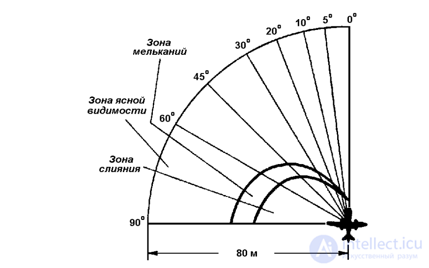
Fig. 2.5. Zones of ground perception during landing (after: Golubev G.G., 1953)
According to G.G. Golubev (1953), the surface of the airfield, as seen by the pilot during
a landing, is divided into three zones (Fig. 2.5): – a zone of clear visibility; – a
flicker zone; – a fusion zone (the space over the terrain in which, because of high speed, it is
impossible to perceive individual objects, so that only a solid band is seen).
The functioning of the visual analyzer and the emergence of visual sensations
obey certain rules and laws which aviation specialists absolutely must take into account.
The law of contrast (contrast sensitivity of vision). The law of contrast is as follows: the more weakly an object is illuminated and the farther it is from the observer, the greater must be the contrast for reliable discrimination of the stimuli. This law imposes strictly defined requirements on the placement of images on aviation diagrams and instruments. Two kinds of brightness contrast are distinguished: direct and
reverse. If the observed object is darker than the background, the contrast is called direct;
if the object is brighter than the background, the contrast is reverse. In practice, a contrast of 85–90% is most optimal (Denisov V.G., Onishchenko V.F., Skripets A.V., 1983).
Indicator instruments in aviation can have either direct or reverse contrast. Indicators with direct contrast create better conditions for the eye to work than indicators with
reverse contrast.
Dynamic visual acuity (perception of moving objects). The perception of
the motion of objects is especially important during aircraft takeoff and landing and during
low-altitude flight. Visual acuity depends on the speed of movement
of the object: the greater the speed, the higher the threshold of visual acuity. The speed at which the gaze can shift and the accuracy of perceiving instrument
information largely depend on dynamic visual acuity. During landing, in order to obtain instrument
information on the position of the aircraft, the pilot changes the direction of gaze from 130 to 200 times per minute (Denisov V.G.,
Onishchenko V.F., Skripets A.V., 1983). The stability of dynamic visual acuity decreases under vibration.
Eye adaptation. The human eye reacts to light radiation in the wavelength range from 380 to 760 nm. In daytime (under daytime, or photopic, vision, involving only
the cones), the maximum sensitivity of the eye falls on a wavelength of 555 nm
(the yellow-green part of the spectrum), while under night (scotopic) vision, involving only the rods, it falls on a wavelength of 507 nm (blue-green rays) (Volkov V.V. et al., 1989). The visual analyzer is able to adapt to seeing under various levels of illumination, and this is the manifestation of the
property of adaptation. Two kinds of adaptation are distinguished: dark adaptation (the eye's adjustment to seeing in darkness) and light adaptation (adjustment to seeing under bright illumination). Adapting the
eyes takes a certain amount of time. In the course of dark adaptation, the eye's sensitivity to
light first increases rapidly, and after just 25–40 minutes it increases 15,000-fold (Denisov
V.G., Onishchenko V.F., Skripets A.V., 1983). After spending 60–80 minutes in darkness, the eye's sensitivity increases 200,000-fold. In the transition from darkness to light, initial
adaptation lasts 1–2 minutes, while final adaptation takes 3–8 minutes.
Disregarding the laws of dark and light adaptation leads to the pilot incorrectly judging
the distance to the ground. An illustration of this can be seen in the emergence of
a «light screen» as a result of turning on landing lights in fog, haze, precipitation, or cloud. Thus,
during an approach to landing of a Tu-134 aircraft with the landing lights on, in the presence of haze and
rain, a light screen arose, and the aircraft commander gave the order to switch off the lights,
after which the crew could not immediately adapt to the darkness, and as a result control of the distance to the ground was lost. The result of this was a high flare of the aircraft and
a subsequent hard landing (Onufrash A.I., 1981, a). The occurrence of a light screen
is a common phenomenon. Thus, on 6 January 2000, the commander of an An-24 aircraft at an altitude of 30
m and a speed of 220 km/h gave the order to turn on the landing lights, but because a light screen formed, they were switched off (Information Bulletin…, 2001, No. 4). On a repeated approach
to landing of an An-12 aircraft at Anadyr airport (8 February 1994) with a visibility of «80 ×
1,000 m», the landing lights were switched on, and because of the resulting light screen the crew lost visual contact with the runway, which was not regained even after the lights were switched off (Analysis…, 1995). In the course of the subsequent descent, the aircraft drifted 57 meters to the left
of the runway centerline and landed on unpacked snow to the left of the runway, 730
meters from the threshold, sustaining significant damage as a result. Since the light screen occurs quite frequently, one must be prepared for it – the mere presence of haze,
cloud, fog, or precipitation should indicate a high probability of the screen appearing.
Experiments conducted by V. Koblyansky (1974) showed that regular intake
by pilots of vitamins A (retinol – retinolum), B1 (thiamine – thiaminum), B2 (riboflavin –
riboflavinum), B6 (pyridoxine – pyridoxinum), PP (nicotinic acid – acidum nicotinicum),
and C (ascorbic acid – acidum ascorbinicum) contributed to an improvement in the rate
of dark adaptation and to a faster recovery of night visual acuity after exposure to dazzling glare.
Let us now examine the organization of the organs of hearing and balance – the next most important analyzer systems. The outer ear includes the external auditory canal, 3.3–
3.5 cm long and 0.6–0.9 cm in diameter, the auricle, and also muscles and ligaments. The boundary between
the outer and middle ear is the eardrum, which is only 0.1 mm thick.
The middle ear is represented by three auditory ossicles (malleus, incus, stapes) located in the tympanic cavity (with a volume of 1 cm3
)
and by the auditory (Eustachian) tube,
3.5 cm long (Fig. 2.6). The latter connects the tympanic cavity with the nasopharynx and serves
to equalize pressure between these cavities.
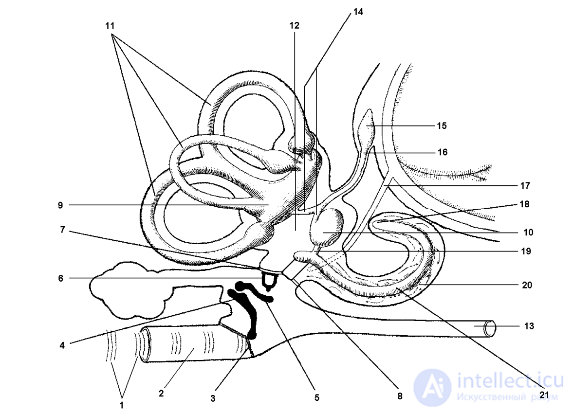
Fig. 2.6. Organization of the middle and inner ear
(after: Physiological…, 1985; from: Histology…, 2001)
1 – sound waves; 2 – external auditory canal; 3 – eardrum; 4 – malleus; 5 – incus; 6 – stapes; 7 – oval window; 8 – round window; 9 – utricle; 10 – saccule
; 11 – semicircular ducts, located in the bony semicircular canals; 12 – vestibule; 13 –
auditory (Eustachian) tube; 14 – duct of the utricle and saccule; 15 – endolymphatic sac; 16 – endolymphatic duct; 17 – perilymphatic duct, or cochlear aqueduct (connects the perilymphatic space with the subarachnoid space); 18 – opening of the cochlea, or helicotrema (a communication between the scala vestibuli and the scala tympani at the apex of the cochlea); 19 – connecting
duct; 20 – scala tympani; 21 – cochlear duct
The inner ear is represented by the membranous labyrinth, consisting of the utricle
and saccule of the vestibule, three semicircular ducts, and the cochlea (Fig. 2.6, 2.7).
The membranous labyrinth is embedded in a bony capsule – the bony labyrinth. The membranous
labyrinth is filled with a special fluid – endolymph (Gr. endon – inner + Lat. lympha –
moisture). The space between the membranous and bony labyrinths is filled with perilymph
(Gr. peri – around + Lat. lympha – moisture).
The inner ear contains the receptor apparatus of two analyzers: the auditory (the cochlea) and
the vestibular (the utricle and saccule, located in the vestibule
(the vestibule being part of the bony labyrinth), and the semicircular ducts, located in the bony cavities that repeat their shape – the semicircular canals).
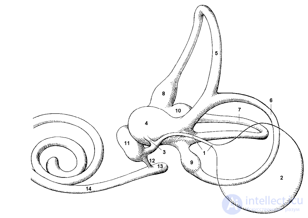
Fig. 2.7. Organization of the membranous labyrinth
(after: Fenish H., 1996):
1 – endolymphatic duct – a duct originating from the duct of the utricle and saccule, passing through the vestibular aqueduct and terminating in an expansion – the endolymphatic
sac; 2 – endolymphatic sac – located on the posterior surface of the temporal bone's pyramid between
two layers of the dura mater of the brain; 3 – duct of the utricle and saccule –
connects the saccule and the utricle to one another (the point of origin of the endolymphatic duct); 4 – utricle – the point of origin of the three semicircular ducts; 5 – anterior semicircular
duct – one of the three semicircular ducts, located in a vertical plane and oriented almost perpendicular to the long axis of the temporal bone's pyramid; 6 – posterior semicircular duct –
one of the three semicircular ducts, located in a vertical plane and parallel to the long
axis of the temporal bone's pyramid; 7 – lateral semicircular duct – one of the three semicircular ducts,
oriented in a horizontal plane; 8 – anterior membranous ampulla – an expansion of the anterior semicircular duct; 9 – posterior membranous ampulla – an expansion of the posterior semicircular duct; 10
– lateral membranous ampulla – an expansion of the lateral semicircular duct; 11 – saccule
; 12 – connecting duct (connects the saccule with the cochlear duct); 13 – blind
vestibular protrusion – the blind end of the cochlear duct facing the vestibule; 14 – cochlear
duct – a tube of triangular cross-section, coiling around a bony axis
and ending blindly at the apex of the cochlea
The vestibular (Lat. vestibulum – entrance hall) apparatus is a biological transducer of acceleration energy into bioelectric signals, which travel along conducting
pathways to the corresponding nerve centers, where the position of the head and body
in space is analyzed. Receptors located in the semicircular canals respond to angular
accelerations, while receptors located in the utricle and saccule of the vestibule (otolithic receptors) respond to linear accelerations. In each ampulla of the semicircular ducts there are special sensory (neurosensory, or receptor) areas called cristae, or crests. The sensory areas in the utricle and saccule of the vestibule are called maculae.
The epithelium of both the cristae and the maculae is composed of hair cells and supporting cells
(Fig. 2.8).
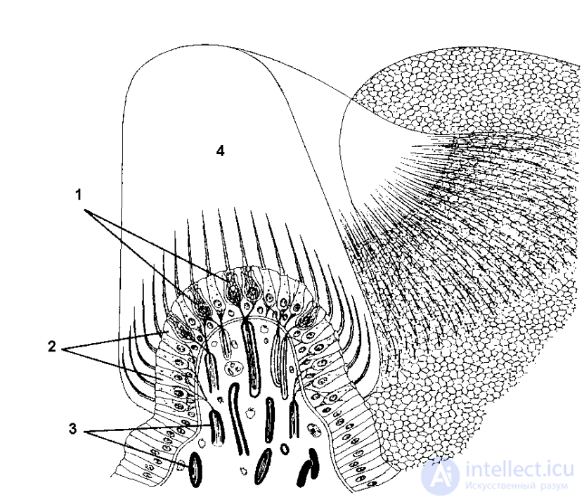
Fig. 2.8. Structure of the crista (crest)
(after: Basic histology, 1998; from: Histology…, 2001)
The neurosensory epithelium (neuroepithelium) is formed by hair cells (1) and supporting cells (2).
Type I hair cells are located at the center of the crest, and type II hair cells at the periphery. The hair cells
form synapses (a type of intercellular contact) with afferent nerve endings (3).
The cupula (4) of the crest does not contain otoliths
The epithelium of the maculae is covered by a gelatinous otolithic (Gr. otos – ear + lithos – stone)
membrane (within which are located otoliths – calcium carbonate crystals) (Fig. 2.9),
while the epithelium of the cristae is surrounded by a gelatinous transparent cupula (see Fig. 2.8). In their apical (topmost) part, the hair cells contain from 40 to 110 immobile hairs, called stereocilia, and one cilium, located at the periphery of the bundle of stereocilia and called the kinocilium (Fig. 2.10). Electrophysiological studies have shown that deflection of the hairs of the receptor cells from the stereocilia toward the kinocilium produces an excitatory effect, while deflection from the kinocilium toward the stereocilia produces an inhibitory effect.
Let us consider how the energy of accelerations is perceived by the receptor apparatus of the maculae of the utricle and saccule of the vestibule, and of the cristae of the ampullae of the semicircular ducts. Reception in the maculae occurs as follows: under the action of positive or negative linear accelerations (otolithic receptors specialize in perceiving only the energy of linear accelerations), the otolithic membrane is displaced,
sliding over the hairs of the receptor cells (the sliding occurs because the otolithic
membrane has a different density from the endolymph), which causes the hairs
to bend, giving rise, depending on the direction of movement, to either inhibition or
excitation. The electrical impulses arising in the receptor hair cells
travel along the afferent (sensory, or centripetal) nerve endings (see Fig.
2.10) toward the central nervous system.
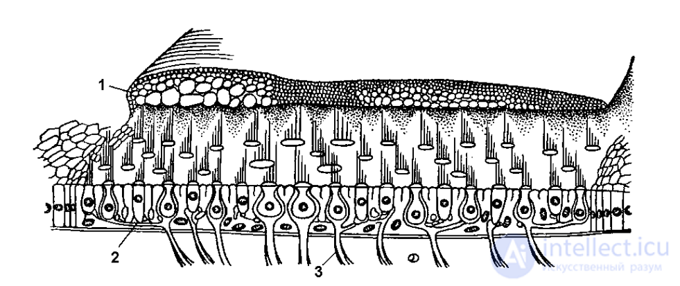
Fig. 2.9. Structure of the macula (spot)
(after: Korobkov A.V., Bashkirov A.A., Vetchinkina K.T., 1980)
1 – gelatinous otolithic membrane, containing calcium carbonate crystals – otoliths; 2 – hair receptor cell; 3 – afferent nerve ending in contact with the hair cell
Reception in the cristae of the ampullae of the semicircular ducts is similar to that in the maculae: a flow
of endolymph, caused by the action of angular accelerations (recall that the receptors of the semicircular ducts specialize in perceiving the energy of angular accelerations), displaces the cupula (see Fig. 2.8) in the direction of its own movement, as a result of which
the hairs of the receptor cells are displaced, which regularly leads to the generation of
electrical impulses transmitted to the afferent nerve endings, along which
they travel to the central nervous system. After the movement stops, owing to its considerable elasticity the cupula tends to return to its initial position. The time required for the cupula to return to its initial position ranges from 1 to 60 s, depending on the nature of the accelerations (Korobkov A.V., Bashkirov A.A., Vetchinkina K.T., 1980).
Nerve impulses from the receptors of the vestibular apparatus travel along the vestibulocochlear nerve (cranial nerve VIII) toward the vestibular nuclei
of the medulla oblongata, and from there to the motor nerve fibers controlling the tone of the body's muscles.
Prolonged excitation of the vestibular apparatus can lead to autonomic
and motor disturbances, well known under the name of «motion (air)
sickness». In the course of studying the functions and connections of the vestibular apparatus, its close connection with the oculomotor system was revealed. Tonic and rhythmic
vestibulo-oculomotor reactions are distinguished. The former refers to the coordinated movement
of the eyes, fixing the gaze on an object during a turn of the head or under linear accelerations (otolithic receptors
participate in this type of reaction). If a component of angular acceleration is present
in a movement of the body, a rhythmic reaction arises involving the receptors of the semicircular canals, which manifests itself in the form of nystagmus.
Nystagmus (Gr. nystagma – sleep, drowsiness) is a coordinated rhythmic oscillation
of the eyes, consisting of slow movements of the eyeballs and fast movements directed opposite to them.
The plane of the nystagmus coincides with the plane of rotation of the body, and accordingly
horizontal, vertical, diagonal, and rotational nystagmus are distinguished. With repeated exposure of the vestibular apparatus to accelerations of one type, the nystagmic reaction diminishes.
People with heightened sensitivity of the vestibular apparatus face restrictions
in choosing a profession, particularly in aviation. In a good pilot, stimulation of the vestibular apparatus is followed by brief nystagmus and insignificant autonomic disturbances. If the opposite is observed, there is an increased probability that the pilot will
incorrectly judge the position, altitude, and character of the aircraft's motion.
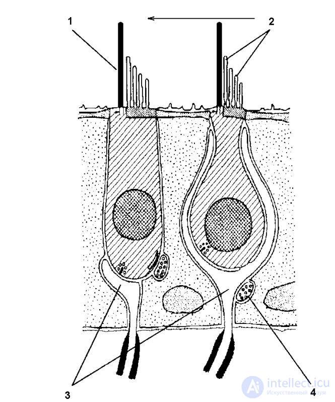
Fig. 2.10. Structure of hair cells (type I cells – on the right, type II – on the left; the arrow shows the direction of hair movement that produces excitation; if the direction is opposite,
inhibition results) (after: Handbook…, 1971; from: Histology…, 2001)
1 – kinocilium; 2 – stereocilia; 3 – afferent (sensory) nerve endings; 4 – efferent (motor) nerve ending
The pilot is subject to rectilinear, radial (centripetal), and angular accelerations, as well as the Coriolis acceleration (rotational acceleration). When the human body is subjected to accelerations, it experiences g-loads. A g-load is a dimensionless quantity showing how many
times the force that caused the body's acceleration or deceleration exceeds its weight. The action of a g-load is due to the inertia of bodies (the g-load is directed against the force that caused the acceleration): on takeoff it is directed against the direction of motion, and on landing – along the direction of motion. If
the direction of the resultant g-load coincides with the direction of gravity (from the head toward the pelvis), it is called positive. If, however, the resultant is directed the opposite way (from the pelvis toward the head), such a g-load is called negative. The effect of g-loads on the body is determined by their magnitude, the gradient of their
buildup, the duration of exposure, their direction relative to the major blood vessels, and
the pilot's psychophysiological state. To express how many times a given acceleration exceeds the acceleration of free fall (9.81 m/s2
), notations such as 3 g, 5 g are used, which
mean that the acceleration acting on the pilot exceeds the acceleration of free fall by a factor of
3 and 5, respectively.
The hardest to tolerate are longitudinal g-loads (directed along the length of the body: either from head to feet, or from feet to head). Longitudinal g-loads in the
«head-to-feet» direction, equal to 2–3 g, press the pilot into the seat while preserving the ability
to perform sufficiently precise movements with the hands and feet (Grabchak P.T., 1975). As the g-load increases to 4–5 g, the following are observed: impaired movement of the arms, a sensation of tension and soreness in the calf muscles, impaired breathing, difficulty in orienting the head in the required position, and sagging of the cheeks and lips. The flow of arterial blood from the heart
to the lower part of the body is facilitated, while to the upper part of the body it is impeded; the return of venous
blood to the heart from the upper part of the body is facilitated, while from the lower part it is sharply impeded
(Grabchak P.T., 1975). At g-loads of 4–5 g lasting more than 5 s, visual disturbances arise (objects are perceived unclearly, and in some cases vision is temporarily lost). Mental functions also suffer under g-load: the span of attention decreases sharply and mental activity slows down. Longitudinal g-loads in the direction from feet to
head are hard to tolerate even at a magnitude of 1 g. At a g-load of 3 g, pulsation
of the arteries in the temple area is felt, and tension of the scalp is noted. At
a g-load of 4–5 g, a characteristic cutting pain in the temples, lacrimation, and nosebleeds occur
(Grabchak P.T., 1975). At higher acceleration values, visual disturbances occur – objects are indistinctly discerned (a gray veil), followed by a further temporary loss of vision (a black
veil).
According to D.V. Gander (2010), it is fundamentally important for the pilot to be able to attach informational meaning to the magnitude, duration, and rate of change of a g-load, characterizing the type and speed of the aircraft's movement in space. If the proposition formulated by D.V. Gander is translated into other terms, it
means that, when the pilot's body is subjected to
a g-load, new conditioned-reflex associations become established in the pilot's psyche: the characteristics of the g-load (as the first of the stimuli) are correlated with the bodily sensations produced by its
action (the second stimulus), as well as with visual (the third stimulus) and instrument (the fourth stimulus) information conveying data on the aircraft's spatial position. The correlation of all four of these stimuli with one another makes it possible
to judge the aircraft's spatial position from the sensations arising under the action of a g-load while performing a specific element of the flight.
It is a common belief that civil aviation crew members do not encounter large
g-loads in flight, which does not correspond to the true state of affairs. Thus, on 19 February
1985, the crew members and passengers (274 people on board in total), flying on a
Boeing 747 from Taipei to Los Angeles, repeatedly experienced alternating g-loads of up to 5 g during the aircraft's uncontrolled descent!
The crew successfully performed an emergency landing with a damaged tail assembly at San Francisco airport (Aircraft accident…, 1986).
Unlike longitudinal g-loads, transverse g-loads are tolerated better. Under the action of
the latter, considerably less displacement of the internal organs is observed (which is determined by their
anatomical arrangement), as is less effect on the major blood vessels. The pilot retains satisfactory working capacity under transverse accelerations of up to 8–12 g and durations of exposure of from 2 to 30 seconds, respectively. In
this case, a slight decrease in visual acuity is noted, and the latent period of motor reactions increases.
Let us proceed to examine the organization of the cochlea (Fig. 2.11) – the structure containing the receptor apparatus of the auditory analyzer. The length of the cochlea is about 35 mm. The cochlea is represented by the cochlear labyrinth, lying within the bony labyrinth, which develops as an outgrowth
of the vestibule. The cochlear canal is divided by two membranes (the vestibular and the basilar) into three
canals (scalae). The upper canal is called the scala vestibuli, or scala
of the vestibule; the lower canal, the scala tympani, or tympanic scala; and the middle canal located between them, the scala media, or membranous canal (cochlear duct).
At the apex of the cochlea, the upper and lower canals of the cochlea are connected to
продолжение следует...
Часть 1 2 SPECIFICS AND CONDITIONS OF FLIGHT ACTIVITY 2.1. THE ROLE OF ANALYZER SYSTEMS IN THE
Часть 2 - 2 SPECIFICS AND CONDITIONS OF FLIGHT ACTIVITY 2.1. THE

Comments