Lecture
There are many diagrams in the UML modeling language. By themselves, they are not something difficult, and they are easy enough to build, even without extensive experience in developing software systems, but only having an initial understanding of the object-oriented approach.
However, in my opinion, the Use Case diagram is the most difficult to understand diagram, namely, what it is for and how to build it correctly. The experience of the trainings that I conducted proves this. Therefore, in this article, I would like to once again focus the attention of readers who use this diagram or one way or another is not indifferent to the UML, on the typical errors that the novice developers of this diagram make.
First, I will formulate a task, by the example of which typical errors will be shown. So, orienteering competitions are popular all over the world. A skier must for a certain time, having a map of the area, pass all the control points that are marked on this map. Currently, there are judges at these checkpoints who mark the fact that the athlete is passing points on the map. However, it is cold in the forest  and therefore I would like to replace the judges with soulless control stations, which would report the fact of passing the control point at the referee's point at the moment when the athlete touches this station with a bracelet with a chip. All information about the course of the competition is displayed on a large scoreboard. In addition, the competition can be monitored via the Internet, subject to the creation of an account on the site and confirmation of this account by the administrator.
That is the problem. Now we will consider why we will use the Use Case diagram here. When we develop a software system it is important to understand for whom we are doing it. Yes, the software system is designed to solve the problems of interested parties, but nevertheless a specific user will work with the program, and it is for the user that we develop it, it is from the user's point of view that we will form the list of functions of our system. It follows that the Use Case diagram is created from the point of view of the users of the system. It should be borne in mind that the user is not part of the system, but only interacts with it - it actively “presses” on the toolbar buttons, in every possible way initiates the work of certain functions of the program. It is the primary (active) actor, which is usually depicted on the left in the diagram. On the other hand, our system interacts on the "client-server" principle with other systems - database servers, various web services, etc. Such systems are secondary (passive) actors and interact with our system only if a request comes from it. Let's see what is shown in this diagram.

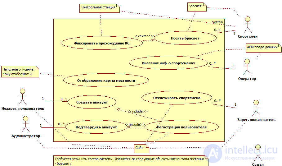
Here we see that some users of our system are designated as secondary actors (those on the right). In fact, this diagram is read as the fact that users have been connected to the computer with wires and periodically charged with current to cause him to respond to this event.  . This is the first mistake.
The second mistake is that here we see the Use Case “Wearing a Bracelet”. This is a user function that is not related to our system at all, and as we have already agreed, the user is not part of the system we are creating. Therefore, this Use Case from this diagram should be removed.
The third error in this diagram is the presence of so-called "suspended Case Use". We have previously discussed that system functions are initiated by the user. In this diagram, we see the Use Case “Record Passage of the CS” and “Displaying a Terrain Map”. Who initiates these functions? The secondary actor cannot do this based on the fact that he himself works on request from our system.
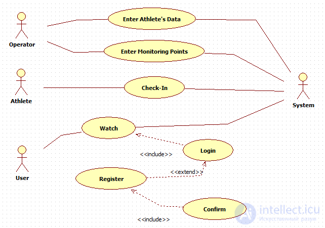
Now I want to draw your attention to another interesting mistake. Let's look at the chart Use Case of another author of the same task:

Here we see a rather strange actor "System". It is very difficult to understand what he will do. Apparently, the developer of this diagram had in mind the very system that we are developing. But recursion does not work here - the system cannot be an actor to itself, based on the definition of an actor, and all the Use Case that we indicate in the diagram relate specifically to our system. Thus, when we indicate an actor, we must clearly understand why it is here, why it interacts with our system, or why we interact with it. By the way, here again we see the previously considered error about the “suspended Use Case”.
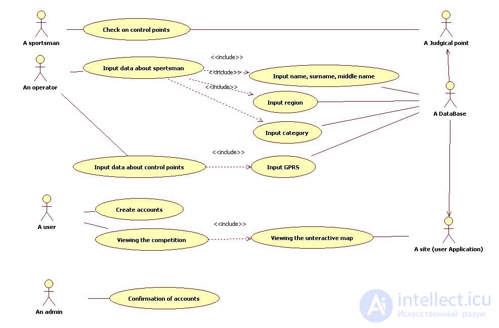
The Use Case diagram is intended to show what functions it provides to the user, but it is not intended to show how the system performs these functions. In this regard, a very common mistake is an attempt to show in the Use Case diagram how certain functions will be performed. There are other UML diagrams for showing “how the system will perform functions”. Let's see an example of such a chart:

Use Case "Input data about spertsman" (the original name given by the author of this chart is preserved) says that here we will enter data about the athlete. Here this information that we just enter the data is enough. And what data it is, we learn from the domain model, where the athlete's attributes are reflected in the class diagram. But here it just does not need to do. In addition, the customer will change the requirements, will make some other characteristics of the athlete that are important to him, and because of this, we rebuild the chart? Therefore, in the Use Case diagram, we only show “what the system will do for the user,” and not “how it will do it.”
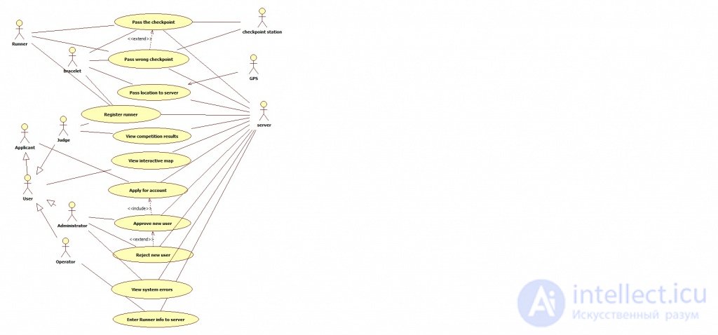
And at the end the most “tasty” mistake of this task. Is the bracelet actor? Let's analyze this chart:

Pay attention to Use Case "Pass the chekpoint". We see that it is initiated by two primary actors, Runner (i.e. athlete) and Bracelet. If everything is clear and logical with the first, then why does the bracelet that is worn on the athlete act as an independent actor? To understand who the bracelet is here, suffice it to say that in the Use Case diagrams, the connection between the actor and the Use Case (in the UML world called association) essentially means the user interface when we talk about the primary actor, and the interface to the external system when we talking about the secondary actor. We are all used to the fact that the user interface is exclusively a UI. And in this task there is no UI for the athlete - there is a control station for him, the interface for which is his bracelet. Thus, if we remove the Bracelet actor from this diagram, everything will fall into place.
We reviewed common errors. Ready to discuss your solution to this problem in the comments.
Extension (eng. Extend) - a kind of relationship of dependence between the basic use case and its special case.
Inclusion (eng. Include) - defines the relationship of the base use case with another use case, the functional behavior of which is always used by the base case of use.
That is, include (arrows go from the base case) illustrates what exactly the base case uses to perform the operation.
So for example - Include - well illustrates the situation that the restoration of the computer is inevitably associated with one of the three actions (suppose that there are no other options):
Thus, from the use case of “restore PC performance”, it can be specified precisely with the help of such “inclusions” - Include. In this case, the use case is not possible without one of the above actions.
While extend indicates the possibility of special use of the base case (arrows go to the base case from special ones)
So, for example - if you return to the situation with a computer - then with the help of extend - it would be possible to extend the option of detecting and deleting a virus - using the option "detecting and deleting and then installing a protection system" - which, however, is not necessary is involved - if the task is to remove the virus.
This non-obligation is precisely the most important difference between extend and include.
Comments
To leave a comment
System modeling
Terms: System modeling