
Lecture
The electromagnetic environment (EME) is understood as the totality of electromagnetic interference generated by any sources in the form of radiation and electric currents (voltages) that affect the operation of radio-electronic equipment (REE), both together with the wanted signal and without it, via the antenna and otherwise.
Interaction between REE of different purposes takes place through electromagnetic fields generated by various sources. In real conditions, a significant part of the set of electromagnetic fields in the area under consideration can and does affect the operation of REE.
The EME can be characterized by certain elementary energy parameters: - operating frequency range;
The interpretation of the EME concept as the set of electromagnetic fields at the observation point that can affect the operation of REE reflects the relativity of this concept. That is, the EME for REE of different purposes located spatially in the same place will be different.
If the EME and its changes do not affect the information characteristics of the received wanted signal, such an EME is favorable for the REE under study. If the EME and its changes cause changes in the information parameters of the wanted signal, such an EME is unfavorable. Both favorable and unfavorable EME can be stable or unstable over time.
Unstable EME is especially often observed when receiving and transmitting equipment is installed on mobile objects. As the observation point moves together with the objects, the EME at that point changes both quantitatively and qualitatively.
Quantitative changes in the EME depend on changes in orientation, the distance to sources of electromagnetic interference, and the radiation pattern of their antennas.
Qualitative changes occur because the observation point may remain constantly within the coverage area of some interference sources while at the same time leaving or entering the coverage areas of other, extraneous REE or sources of unintentional interference.
With respect to a group of REE or its individual elements, the EME can be divided into external and internal.
External EME is considered in the far field of antenna devices and is formed by their radiation fields. In the near field, the EME with respect to REE or their individual parts is regarded as internal EME.
There are several basic approaches to describing the EME: the electrodynamic, energy, and probabilistic approaches. We will focus further on the electrodynamic approach.
The electrodynamic approach is based on solving Maxwell's equations for known (given) sources of the electromagnetic field. In this case, the medium through which the EM waves propagate is assumed to be homogeneous and isotropic.
At the reception point there is usually a combination of signals and interference – the so-called total composite signal. The characteristics of this composite signal depend to a large extent on the radiation patterns of the antennas radiating the wanted signals and the interference, on their frequency and polarization properties, on the distance from the individual sources to the reception point, and on radio-wave propagation conditions.
Under the action of the total composite signal, a multitude of EMFs from its individual components is induced in the receiving antenna, in accordance with the selective properties of the receiving antenna itself.
The main components of the composite signal include constituents concentrated in the spectrum and constituents concentrated in time.
Composite signal at the observation point P(x, y, z) can be found as a superposition of the electromagnetic fields from m individual mutually independent sources.
 (8.1)
(8.1)
If m1, it is quite difficult to estimate the EME using relations (8.1). In addition, the use of the electrodynamic approach is complicated by the fact that the current distribution over the volume occupied by the antenna is not always known.
EMC analysis for a specific situation is carried out on the basis of interaction models. The following kinds of models are distinguished:
In a pairwise assessment, the effect of interference produced by each of two pieces of equipment is taken into account. When there is a large number of them, the pairwise effects of each REE in the given group on every other one are considered.
Group assessment involves studying the effect of a group of sources on a single receptor, or in turn on all receptors of the group.
In a complex assessment, the effect of a group of sources on all receptors that are part of the given set of equipment is considered. The complex assessment is based on the group assessment, and the group assessment, in turn, is based on the use of the pairwise assessment.
Simple interaction logic assumes that each of the devices in the group can be regarded as functionally independent of the other equipment. In this case, the degradation of the individual quality indicators of each REE in the group does not depend on the degradation of the individual quality indicators of other equipment and does not cause their degradation.
With complex logic, it is taken into account that individual pieces of equipment in the group may have functional relationships with one another. The presence of such relationships means that the effect of interference on a certain i -th receptor will not only cause the degradation of its individual indicators but will also entail a change in the quality indicators of another REE.
One of the most common approaches to obtaining such assessments is based on the application of the energy approach and can be used in pairwise, group, or complex assessment of REE EMC.
When assessing EMC, the operating characteristics of the radio channel that determine its main purpose are used as the EMC indicator (EMCI). Such indicators include:
The criterion for ensuring EMC (EMC criterion) is an inequality (possibly a system of inequalities), the satisfaction of which indicates the presence of conditions that ensure EMC (see Appendix 5). When developing EMC criteria, the following should be taken into account:
Because the EME can be unstable, the interference level may change over time, and a single expression for the EMC criterion may prove insufficient. Therefore, two expressions of the EMC criterion are sometimes used: a long-term one (for 20% of the time) and a short-term one (less than 1% of the time).
Pairwise assessment. In the course of developing a particular REE, the designer is primarily interested in how it will function when exposed to this or that interference source, i.e., the pairwise EMC assessment of the REE.
The compatibility conditions are satisfied if the EMC indicator (EMC ) lies within the permissible limits:

where [EMC]adm is the permissible value of the quality indicator. This expression serves in this case as the criterion for ensuring EMC.
Group assessment. The general analysis scheme consists in checking the permissibility of the interference for all receptors in the group.
For the i-th receptor, the compatibility conditions are satisfied if the value of the quality indicator lies within the permissible limits:
 (8.2)
(8.2)
where N is the number of interference sources in the group of equipment under consideration. From the structure of formula (8.2) it can be seen that the quality indicator i depends on the power of the wanted signal at the input of the i-th channel's receiver Psi and the power of each interference source. Formula (8.2) formulates the EMC criterion for the group assessment.
The difference between the group assessment and the pairwise assessment is as follows: in the group assessment, nonlinear phenomena in the sources and receptors must be taken into account first of all.
Therefore, when analyzing EMC within a group of radio equipment, it is necessary to check not only the effect on the receptor of the fundamental and spurious emissions of each transmitter, but also of intermodulation emissions.
For radio receivers, in addition, the effect of interference should be assessed both during reception on the main and spurious channels and as a result of blocking, cross-modulation, and intermodulation.
The features listed sharply increase the volume and complexity of the calculations. Attempts are usually made to carry them out with additional simplifying assumptions. For example, a sequential pairwise assessment is first performed for all source-receptor pairs, then the effect of combinations of two source pairs is considered, and so on.
Complex assessment. It consists in studying the interaction of a group of interference sources with a group of receptors. If the receptors in question form a certain system, the connections between them must be taken into account. Therefore, unlike the group assessment, complex-logic interaction models and a more complex group quality indicator must be used here

Here it is taken into account that individual pieces of equipment in the group may have functional relationships with one another, and the effect of interference on a certain i-th receptor will not only cause the degradation of its individual indicators but will also entail a change in the quality indicator of another REE.
In this case, the criterion is the inequality 
Quality-characteristic stability indicator. For analog systems, the quality-characteristic stability indicator (QCSI) is used, reflecting the quantitative change in the signal-to-interference ratio as the signal passes from the input to the output of the receiver (communication channel):
 , (8.3)
where: Qout = Ps.out / Pi.out is the ratio of the powers of the wanted signal and the interference at the receiver output (or, for multichannel systems, at the output of the communication channel), measured in the frequency band occupied by the message. Qin = Ps / Pi - the ratio of these same quantities at the receiver input
(measured in the frequency band of the input filter (IF amplifier), or in a conventional frequency band, for example, a 4 kHz band).
In communication systems intended for receiving messages in digital form, as well as in data transmission, the main quality indicator is the error probability perr . It is therefore expedient to choose, as the indicator, a quantity that characterizes the relative increase in errors under the effect of interference:
 , (8.4)
here perr is the error probability in the absence of interference, when the receiver input has a wanted signal of power Ps.in and thermal noise of power Pn; perr is the error probability when the receiver input is subjected to a signal of power Ps in , noise of power Pn, and interference of power Pi in .
If several instances of interference can reach the receiver input during the observation period T0 , expression (8.4) becomes more complex:

where M is the number of interfering signals; pi is the probability that interference numbered i reaches the receiver input during the observation period T0; [perr]i is the error probability when the receiver input is subjected to a signal of powerPs , noise of power Pn, and interference numbered i of power [Pi ]i .
Protection-ratio-based indicator. In calculations for analog and digital systems it is sometimes convenient to use, as the EMC indicator, the protection-ratio value Aadm , which defines the ratio Qin Ps / Pi , at which the value of Qout specified by the technical requirements is ensured. It is evident that, for a known value of EMC and a given Qout , the value of Qin can be determined from (8.3).
Note that in some cases, for example in television image transmission systems, the value of Aadm is determined by experts using the method of subjective-statistical evaluation.
Energy-loading-based indicator (EL). The energy-loading-based indicator is the specific value of the effective power radiated by the entire system in a conventional frequency band f, per 1 km of communication link, provided that the required quality of system operation is ensured. Modern radio-communication methods widely use signal retransmission, so the energy-loading indicator can be written in the form
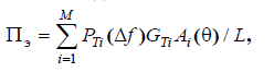
where M is the number of transmitting devices (repeaters) on the radio-communication link of length L , km, along the earth's surface between the terminal stations; PTi (f ), W/Hz is the power supplied to the transmitting antenna of the i-th station in the conventional frequency band f , GTi is the gain of the transmitting antenna of the i-th station; Ai is the attenuation due to the directional properties of the transmitting antenna of the i-th station, is the angle between the direction of the main lobe of the antenna pattern and the direction toward the possible location of another radio system subject to interference.
It is evident that the larger the value of EL , the greater the energy loading of free space and, consequently, the more difficult it is to achieve EMC with such a system.
A comparison of the indicators based on QCSI and EL shows that the former is determined by the modulation and demodulation methods (the system's equipment), while the latter characterizes the possible level of interfering signals created for other systems.
Indicator based on radio-frequency spectrum (RFS) utilization efficiency. This indicator is defined as
 ,
,
where M is the useful result obtained from the radio equipment in question (either the length of the radio-communication link, or the size of the coverage area, channel throughput, or tariff revenue);
f is the frequency band occupied by the radio emission;
V is the volume of free space in which the frequency band f cannot be used by other systems without certain restrictions.
In most cases (but not always), these indicators (and their associated criteria) are a monotonic function of the ratio of the powers (voltages) of signal to interference plus noise.
It is considered that for any particular type of interference it is possible to specify a value of the ratio of the signal power (Ps) to the total power of interference and noise (Pi + Pn) above which no degradation of the REE's quality indicators is observed. In this case, the EMC criterion has the form:

where PEMC is the quality indicator.
To render a binary (yes/no) decision on compatibility, it is necessary to set a threshold level (value) of the quality indicator, exceeding which is impermissible. Such a criterion (method) for EMC assessment is called threshold-based.

Comments