
Lecture
In EMC problems, the term radio transmitter (Tx) covers the transmitter proper, the feeder line, and the antenna. The main functional purpose of a Tx is to generate the carrier harmonic oscillation, modulate it, and form electromagnetic oscillations that are fed through the feeder to the antenna and then radiated as electromagnetic waves freely propagating in space.
According to the Radio Regulations, Tx emissions must be designated in accordance with the necessary bandwidth and the type (class) of signal.
Necessary radio-frequency bandwidth (denoted Bn ) is the minimum bandwidth of a given class of radio emission that is sufficient to transmit the useful signal at a given rate and with the required quality.
The value of the necessary bandwidth (NBW) of an emission is indicated before the designation of its class and contains three digits and one letter. The letter symbol plays the role of a decimal separator, separating the integer part from the fractional part, and indicates the unit of measurement of the bandwidth.
Values of Bn are expressed as follows:
Example 3.1.
0.002 Hz – H0024; 2.75 kHz – 2K754; 410 Hz – 410H; 3.25 GHz – 3G25; 36.47 kHz - 36K5 (rounded to three significant digits).
Depending on their characteristics, Tx emissions are classified according to certain criteria. Moreover, the designation of each class contains, in coded form, indications of the primary and additional characteristics of the oscillations generated by the transmitter and of the radiated radio signal.
Class of radio emission ̃ is a set of characteristics expressed by conventional designations of the types of modulation, the modulating signal, and the transmitted messages, and (where necessary) additional characteristics of the signal.
Each class of radio emission is designated by a three-character symbol covering the main features of the emission.
The first mandatory element (a letter) characterizes the type of modulation of the main carrier, the second mandatory element (a digit) characterizes the signal modulating the main carrier, and the third mandatory element (a letter) indicates the type of information transmitted (see Table A1.1… A1.3, Appendix 1).
If a more detailed classification of the radio emission is required, the mandatory three-character symbol of the corresponding emission class is supplemented with two more elements.
Example 3.2. The most common classes of radio emission.
Double-sideband telephony with amplitude modulation (A3).
A3E (A – double-sideband amplitude modulation, 3 – one information channel, E – telephony, including sound broadcasting).
A3EGN (G –monophonic broadcasting, N – no multiplexing).
Single-sideband modulation:
H3E – single-sideband transmission with full carrier.
R3E – single-sideband transmission with reduced carrier. The carrier emission level still allows it to be recovered and used during reception.
C3F – single-sideband transmission with a vestigial (partially suppressed) sideband. This class of radio emission is used in television, its distinctive feature is the suppression of the upper part of the spectrum of one of the sidebands. Retaining the low-frequency part of the vestigial sideband is necessary for better image reproduction.
C3FNN - color image.
Frequency modulation:
F8EHN – FM stereophonic broadcasting.
F3EGN – sound accompaniment.
Pulse modulation:
P0N – shipborne radar (sequence of unmodulated pulses).
QXN – radar with linear frequency modulation.
Each Tx is allocated a specific frequency band depending on the class of emissions it generates.
Necessary emission – is the electromagnetic emission of a Tx within the necessary radio-frequency bandwidth that is used to transmit the useful signal. Alongside the necessary emission, the operation of transmitting equipment is accompanied by numerous unwanted emissions.
The parameters of a radio station's necessary emission within the necessary bandwidth include:
|
Parameters |
Units of measurement |
|
- carrier frequency and its deviation, |
Hz |
|
- necessary bandwidth, |
Hz |
|
- output power, |
W, dBW |
|
- surface power flux density for onboard satellite REE, |
W/m2, dBW/m2 |
|
- type and parameters of modulation |
|
|
- attenuation of the carrier oscillation and suppression of the non-working band for single-sideband Tx |
dB |
An approximate spectrum of emissions generated by a Tx is shown in Fig. 3.1.
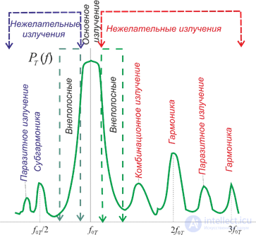
Figure 3.1 – Power spectrum of Tx emissions
A source of information on the parameters of the necessary emission can be the technical description, which specifies the nominal emission power, the transmitter's operating frequencies, and the type of signal modulation.
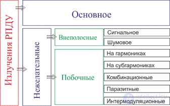
Figure 3.2 –̃ Classification of Tx emissions
Unwanted emissions. Their frequencies lie outside the necessary bandwidth. Their distinguishing feature is that they are not necessary for the transmission of useful information. Unwanted emissions are divided into out-of-band and spurious emissions.
Out-of-band emissions – are emissions in frequency bands immediately adjacent to the necessary bandwidth, arising as a result of modulation of the useful signal.
The causes of out-of-band emission can be:
In practice, most radio stations have non-optimal (imperfect) emission, in particular due to the presence of out-of-band emissions whose frequencies lie beyond the necessary bandwidth. They degrade EMC conditions by interfering with REE operating in neighboring adjacent frequency bands.
To assess the actual (imperfect) emission, the concept of occupied bandwidth Bo has been introduced. According to previously established standards, the width of the occupied bandwidth of all classes of radio emission must not exceed the width of the necessary bandwidth by more than 20 %.
Occupied radio-frequency bandwidth is defined as the band outside of which a certain fraction of the average radiated power, equal to β (usually 1%) of the average emitted power of the given radio station at its assigned frequency, is radiated.
The value β is determined separately for each specific class. At β =0.5, 99 % of the average power is radiated within the occupied bandwidth.
From the standpoint of radio-frequency spectrum (RFS) usage, an emission is considered perfect if the width of the occupied bandwidth is equal to the necessary bandwidth (as shown in Fig. 3.3).
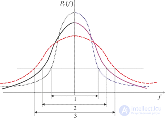
Figure 3.3 – Relationships between occupied and necessary bandwidth:
In order to have information on the shape of the power spectral density envelope of the emission and on the rate of decrease of the out-of-band spectral components beyond the necessary bandwidth, the concept of the bandwidth BX at the level - X dB relative to the level of the necessary emission, taken as 0 dB, is introduced.
Beyond the band BX the intensity of any spectral components or the power spectral density of the out-of-band emission is attenuated relative to the level of the necessary emission by at least X dB. Using several levels (for example, X=-30,-40,-50 dB) makes it possible to monitor the rate of decrease of the out-of-band emission. Usually X 60 dB is taken as the lower level.
Monitoring and standardization of out-of-band emission is carried out using the concept of the reference bandwidth, beyond which any spectral component is attenuated by 30 dB.
The line passing through the permissible values of levels X of the emission spectrum (for example, 0...-30...X ...- 60), is called the limiting line. It defines the upper boundary of the maximum permissible values of the components of the out-of-band emission power spectrum. The bandwidth values (Bn , Br , BX , Bo ) are standardized for different emission classes.
Spurious emissions – are a broad class of emissions caused by nonlinear processes occurring in the Tx during the formation of the transmitter's carrier frequency and the amplification of RF oscillations. This class includes: harmonic and subharmonic emissions, combination, intermodulation, and parasitic emissions.
Harmonic emissions – are spurious emissions whose frequencies are an integer multiple of the carrier frequency of the necessary emission. If f0T – is the carrier frequency, then the frequency of the N -th harmonic ( fN ) is determined by the relation
fN = Nf0T N = 2,3,...
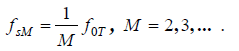
Subharmonic emissions – are spurious emissions at frequencies that are an integer number of times lower than the carrier frequency of the necessary emission. The transmitter's subharmonics are harmonics of the master oscillator, so the number of subharmonics is limited by the frequency multiplication factor of the master oscillator.
The frequency of the M -th subharmonic ( fsM ) is determined by the relation:
Combination emissions arise in a Tx where the necessary emission is formed by frequency conversion of several auxiliary oscillations. They are typical of band transmitters whose exciters provide the required frequency grid based on a system containing one or several crystal oscillators.
Parasitic emissions – are spurious emissions arising as a result of self-excitation of the radio transmitter due to the presence of parasitic couplings in the oscillator or amplifier devices or in its stages.
The frequencies of parasitic emissions are in no way related to the main frequency of the transmitter or to the frequencies of oscillations arising in the process of its formation and modulation.
Intermodulation emission – is a spurious emission arising as a result of the action, on the nonlinear elements of the RF path of a radio transmitter, of the oscillations it generates together with oscillations arriving from outside

It can arise when several transmitters operate simultaneously, especially when working into one antenna or closely located antennas. In this case, a certain part of the power of one transmitter can penetrate into the output stages of the power amplifiers of another transmitter operating in a nonlinear mode. As a result, components whose frequencies are linear combinations of the frequencies of the transmitters mentioned may appear in the emission spectra generated by these transmitters.
The output power of a radio transmitter should be understood as the active power delivered by it to the antenna-feeder device or to a load equivalent. It can be expressed as the carrier, average, peak, or pulse power.
Carrier power of a radio transmitter – is the output power during continuous emission without modulation of the carrier.
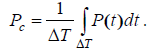
Average power – is the output power of a normally operating radio transmitter, defined as the average value of the power over a time exceeding the period ΔT of the lowest frequency of the modulating signal, during which the average power is maximum.
Peak power – is the output power of a radio transmitter corresponding to the maximum amplitude of the radio-frequency signal.
Ppk = Umax2 / RL .
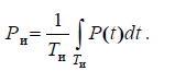
Pulse power – is the output power of a radio transmitter, defined as the average value of the power over the time Tp of pulse emission.
To solve EMC problems of REE, it is necessary to know not only the output power but also the amount of power radiated by the Tx in a given direction – the effective radiated power.
Effective radiated power is defined as the product of the power delivered to the antenna and the gain of that antenna in a given direction, measured relative to a reference antenna.
Equivalent isotropically radiated power is defined as the product of the power delivered to the antenna and the gain of that antenna in a given direction, measured relative to an isotropic antenna
Depending on its purpose, a Tx has its output power or equivalent isotropically radiated power standardized.
Under the deterministic approach, the nominal power of the transmitter is the parameter that determines the power of a possible source of interference.
The statistical approach to describing the necessary emission assumes that the power is a random variable which, when expressed in decibels relative to a milliwatt or watt, has a normal probability distribution with a mean value equal to the nominal power of the transmitter, and a standard deviation determined by the power spread tolerance. It is recommended to take the standard deviation of the nominal transmitter power σT equal to 2 dB

Comments