
Lecture
The electromagnetic compatibility of a set of transmitting (radiating) and receiving devices is determined not only by the electromagnetic environment at the locations of the receptor antennas but also by the susceptibility of the latter to the electromagnetic field of the interference.
The main reception channel is the name given to the frequency band intended for receiving the wanted signal. The width of this band BR is usually determined at the 3 dB level relative to the value of the frequency selectivity characteristic at the frequency of the wanted signal (the receiver tuning frequency). An ideal receiver-receptor should have only one main reception channel.
A measure of the linearity of the main reception channel is its dynamic range, at which the nonlinear distortion factor equals the permissible value, and the signal/noise ratio at the output Qout equals a specified value

where Emax and Emin are the maximum and minimum amplitude of the wanted signal at the input at the receiver tuning frequency f0R .
In real conditions, in addition to the main reception channel, there are also undesirable, spurious channels, in frequency bands located outside the band of the main channel.
Moreover, interference that degrades EMC conditions can penetrate to the receiver output either through the main reception channel or through spurious channels. In addition, the interference frequency may not coincide with the frequencies of the main and spurious reception channels, and its level may reach a magnitude such that nonlinear effects of blocking, cross-modulation, and intermodulation arise in the receiver stages.
Susceptibility of a radio receiver is the property of the device to respond to electromagnetic interference acting through the antenna and otherwise, and depends on the sensitivity and selectivity of the receiver for the main and spurious reception channels. Such interference may also act through shields, as well as through power supply and switching circuits.
The parameters that determine the susceptibility of a radio receiver include:
The ability of a receiver to extract the wanted component from the set of components of the signal at the input is called selectivity.
Several types of selectivity are distinguished:
The frequency selectivity characteristic is the dependence of the signal level at the radio receiver input on frequency for a given signal-to-noise ratio or signal level at its output. In superheterodyne radio receivers, the selectivity for the main and spurious reception channels is determined by the radio-frequency (RF) stages (Figure 7.1)
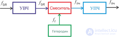
Figure 7.1 Functional diagram of the RF part of the receiver
Figure 7.2 shows an example of a single-signal typical selectivity characteristic of a superheterodyne receiver, which describes the selective properties of the receiver in the linear or near-linear operating modes.
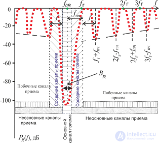
Figure 7.2 Frequency selectivity characteristic
Under multi-signal exposure, frequency selectivity characterizes the ability of the receiver to extract the wanted signal against the background of its own noise and interfering radio signals acting at its input. It is determined by the ratio of the amplitudes of signals simultaneously arriving at the receiver input at one or several given frequencies and at the receiver tuning frequency, for a given ratio of wanted-signal power to interference-component power at its output.
The bandwidth of the main reception channel BR is usually chosen equal to the required bandwidth Bn, taking into account the permissible frequency mismatch Δf on both sides of the tuning frequency
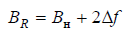
where  and
and are the relative instability of the tuning frequencies of the transmitter and receiver, respectively.
The ideal selectivity characteristic within the main reception channel, unlike the one shown in Figure 7.2, would have a rectangular shape. In this case, the components of the wanted signal would reach the receiver output without attenuation, while interference outside this band would be completely suppressed. An idea of how close the real and ideal selectivity characteristics are is given by the rectangularity coefficient.
The rectangularity coefficient at level X (dB) is the ratio of the bandwidth at that level to the bandwidth at the 3 dB level (for broadcast receivers X is usually 60 dB, for fixed-service receivers X = 30 dB).
kX = BX / BR .
A receiver has a good rectangularity coefficient if k60 = 2...4, and a low one if k60  8.
8.
Out-of-band (adjacent) reception channels adjoin the main reception channel directly. These channels are formed in the intermediate- and radio-frequency amplifiers and are due to insufficient selectivity of the corresponding stages. The magnitude of the attenuation of interference penetrating from adjacent channels is standardized. Thus, for household AM radio receivers, the standards require that the single-signal selectivity for the adjacent channel, which determines the interference attenuation, be at least 26…56 dB, depending on the receiver class.
Spurious reception channels – these are frequency bands located outside the main reception channel, in which interference can penetrate to the receiver output. The following reception channels are classified as spurious. Spurious reception channels (Figure 7.3) are formed in mixers. They arise due to insufficient selectivity of the preceding channels and are determined by the nonlinearity characteristic of the mixer.
The spurious reception channel at the image frequency (image channel). It is formed as a result of insufficient interference attenuation in the receiver's preselector (input circuits and RF amplifier). If the local oscillator frequency is chosen higher or lower than the receiver tuning frequency, then the mean frequency of the image channel is

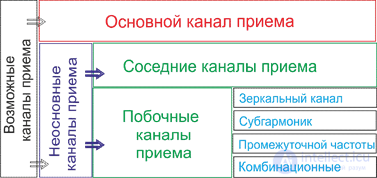
Figure 7.3 Classification of reception channels
Combination reception channels. In the general case, for interference with frequency fi, the frequency of the combination channel fc , through which the interference may pass, is determined from the relation

where i ,n and m - are positive integers;
flo - local oscillator frequency;
fif - intermediate frequency;
Bif - the bandwidth of the receiver's IF amplifier.
The value N =n+m is called the order of the combination channel.
Subharmonic channels of the receiver tuning frequency are formed, for example, upon interaction of the first harmonic of the local-oscillator frequency (m =1) and the second harmonic of the interfering signal (n = 2) . This forms the subharmonic frequencies of the receiver tuning frequency fsh = 0.5( flo - fif ) = 0.5 fR and the image-channel frequencies.
The intermediate-frequency reception channel of the receiver is formed due to insufficient selectivity of the receiver's preselector. In trunk radio communication receivers of classes 1, 2, and 3, interfering signals at the intermediate frequency must be attenuated by at least 100, 80, and 60 dB, respectively, and in household AM radio receivers by at least 40…26 dB. The stronger the nonlinearity in the frequency-conversion process in the mixer, the more harmonics appear and the more spurious reception channels associated with them.
The selectivity of spurious reception channels is likewise determined by its own passband and rectangularity coefficient. In EMC problems, the shape of the selectivity characteristic for spurious channels is usually taken to be the same as for the main channel, but the spurious channels differ from the main one in their sensitivity.
The dynamic range for the spurious channel characterizes the selectivity of the receiver with respect to interference on the spurious reception channel.


where Ps - power of the wanted signal;
Psc - power of interference in the spurious channel;
Pn- power of internal noise.
Sensitivity on the main channel is called the sensitivity of the receiver. Quantitatively, sensitivity (also known as real sensitivity) is determined by the voltage or signal power at the input at which a given signal/noise ratio Qout is provided at the receiver output at the rated output signal power.
The technical specifications or standards stipulate the signal-to-noise ratio at which sensitivity is measured (for broadcast AM receivers, LF, MF, and HF, Qout = 20 dB; for higher frequencies, 26 dB; in the VHF band with frequency modulation, Qout 50 dB). Sensitivity is measured in microvolts, watts, or decibels relative to a microvolt, watt, or milliwatt.
Real sensitivity, limited by the receiver's own noise, can be calculated using the formula:
Pmin = NnkBToBnQout [W],
where Pmin - receiver sensitivity at the operating tuning frequency f0R ;
Nn - receiver noise figure (in multiples);
kB =1.38 10-23W/Ko/Hz - Boltzmann's constant;
T - temperature in degrees Kelvin;
Bn  Bif - the effective noise bandwidth of the receiver, Hz.
Threshold sensitivity is determined by the minimum level of the wanted signal at the radio receiver input at which the levels of the wanted signal and the receiver's own noise at its output are equal, i.e., at a signal/noise power ratio of 0 dB. Such sensitivity is calculated using the formula:
Pmin = NnkBToBn .
Susceptibility of spurious reception channels is expressed in decibels relative to the sensitivity of the main channel. This parameter shows how much worse the sensitivity of the spurious channel is compared with the sensitivity of the main channel.
At a sufficiently high level, interference acting on one of the adjacent reception channels and not passing to the receiver output can cause the blocking effect on the wanted signal.
Blocking in a radio receiver is a change in the signal level or the signal/noise ratio at the output of the radio receiver under the action of interference whose frequency does not coincide with the frequencies of the main and spurious reception channels. Blocking occurs in the first stages of the radio receiver due to the nonlinearity of the current-voltage characteristic of the active components used.
The current-voltage characteristic of the nonlinear element can be approximated by a Taylor series and represented by a truncated third-degree polynomial
 , (7.1)
where Uin - input voltage;
b0 ,b0' ,b0'' - the slope of the current-voltage characteristic and its two derivatives.
Since only the odd terms of series (7.1) participate in the formation of the amplitude characteristic of the amplifier stage, then, excluding the zero and quadratic terms of the series, we obtain
 . (7.2)
Substituting into (7.2)  and, since only oscillations at the signal frequency pass to the receiver output while all other components are suppressed in the filtering process, we obtain the expression for the amplitude of the first harmonic of the current at the wanted-signal frequency
 , (7.3)
where Es and Ei are the amplitudes of the wanted signal and the interference, respectively.
Equation (7.3) is the amplitude characteristic of the nonlinear element, determining the dependence of the amplitude of the first harmonic of the wanted-signal frequency on the levels of this signal and the interference at the receiver input. Here bav is the average slope of the current-voltage characteristic of the active element (diode, transistor, etc.), which depends on the amplitudes of the wanted signal and the interference. For strong interference, expression (7.3) can be simplified

then the average slope bav = (b0 +b0''Ei2 / 4) depends only on the interference power. The ratio b0'' / b0 is a parameter characterizing the nonlinearity of the active element used, which is the cause of the blocking effect.
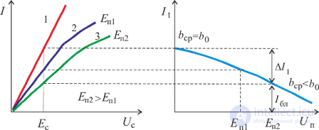
a) b)
Figure 7.4 Effect of blocking
During blocking, under the influence of radio interference, there is a decrease in receiver gain (usually in the first stages, which, due to the low selectivity of the preselector, are in the worst conditions for interference protection). The blocking effect is stronger the higher the interference level and the closer its frequency is to the main reception channel. When b0'' 0, the amplitude characteristic is linear (curve 1 in Figure 7.4, a), its slope is maximal, and the amplitude of the first harmonic does not depend on the action of the interference. When b0'' 0, the amplitude characteristic is nonlinear (curves 2 and 3), the average slope bav b0 and the current amplitude decreases as the interference power increases (Figure 7.3, b).
The permissible decrease in signal level during blocking is 3...6 dB. The frequency band in which blocking occurs is called the blocking band Bbl . The frequency of the blocking interference may coincide with the frequencies of adjacent reception channels
A quantitative characteristic of the blocking effect is the blocking coefficient, numerically equal to the ratio of the change in signal amplitude at the receiver output under the action of interference to the signal amplitude in the absence of interference:
 . (7.4)
In the absence of blocking, kbl 0; at full blocking, kbl 1. The permissible values are 0.3...0.5.
The frequency selectivity characteristic of a receiver with respect to blocking is the dependence of the radio interference level at the receiver input on frequency at a constant blocking coefficient.
The dynamic range for blocking Dbl 0 is quantitatively estimated as the ratio of the harmonic interference at the receiver input Ui in to the sensitivity Us in for given blocking coefficient and frequency offset of the interference relative to the mean frequency of the main reception channel

Thus, strong interference on an adjacent channel can also cause distortion of the spectrum structure of the signal at the receiver output – cross-modulation distortion.
Cross-modulation distortion – is a change in the spectrum structure of the wanted signal at the radio-receiver output under the action of a modulated interference whose frequency does not coincide with the frequencies of the main and spurious channels. This distortion arises in the RF amplifier and the mixer of the receiver under the action of a modulated interfering signal with a frequency close to the receiver tuning frequency on these elements (for example, at the frequency of the adjacent channel).
Under the action of AM interference and an unmodulated wanted signal, the voltage acting at the input of the nonlinear element is
 (7.5)
(7.5)
After substituting (7.5) into (7.2), we obtain the expression
 . (7.6)
The second term in (7.6) reflects the blocking effect, and the third reflects the cross-modulation effect, as a result of which components appear in the spectrum of the output signal at frequencies  . When
  these interference components fall within the passband of the main reception channel and pass to the output.
Consequently, cross-modulation distortion manifests itself in that the modulation of the interfering signal, all of whose spectral components lie outside the receiver's passband, is transferred onto the wanted signal. The depth of cross-modulation
mcross = b0''Ei2 / 2b0 .
If the interfering signal is modulated at frequency and the wanted signal is modulated at frequency
  , then the cross-modulation distortion coefficient kcross is determined by the ratio of the increment of the first harmonic of the output current due to the interference
  to the increment of the first harmonic of the output current due to the wanted signal
 .
.
kcross =Uout cross /Uin s =b0''Ei2mi / 2b0ms .
The frequency selectivity characteristic for cross-modulation distortion is the dependence of the level of modulated interference at the receiver input on frequency at a fixed cross-modulation distortion coefficient.
The dynamic range of the receiver for cross-modulation distortion is defined as the ratio of the level of modulated interference to the receiver sensitivity, at a given cross-modulation distortion coefficient and frequency offset of the interference relative to the central frequency of the main reception channel.
Dcross = 20lg(Ucross /Us) at kcross = const .
Under multi-signal exposure, intermodulation effects may occur, which must be taken into account when analyzing EMC.
Intermodulation (mutual modulation) – is the occurrence of interference at the radio-receiver output under the action, at the input, of two or more radio interferences whose frequencies do not coincide with the frequencies of the main and spurious reception channels.
Dangerous intermodulation oscillations of order 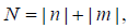 can fall within the receiver passband if the inequality holds
 , (7.7)
where f1 and f2 – frequencies of the interfering signals, f0R receiver tuning frequency; BX passband of the IF amplifier at level X dB, n,m 1,2,3,... For evaluating intermodulation interference, the IF frequency band is usually chosen at the 60 dB level.
The greatest interfering effect can be caused by second- and third-order intermodulation interference of the form:  ,
,
where f1 - the frequency closest to the receiver tuning frequency,
f2 - a more distant frequency,
fR - the frequency falling within the main reception channel.
If the frequency of the intermodulation interference falls within the receiver passband, it passes to the output and disrupts reception of the wanted signal.
An example of the position of interfering signals on the frequency axis is shown in Figure 7.5.
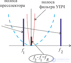
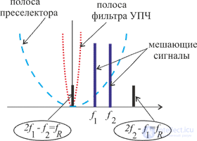
Figure 7.5 Formation of intermodulation interference
When intermodulation interference occurs, the total voltage of the wanted signal and the two interfering signals acts at the input of the nonlinear element
 (7.8)
(7.8)
After substituting (7.8) into (7.2), we obtain the expression for the amplitude of the first harmonic of the current at the signal frequency
 (7.9)
(7.9)
The second term in (7.9) reflects the contribution of the intermodulation interference.
Receiver susceptibility to intermodulation is characterized by the intermodulation coefficient kim , defined as the ratio of the level of intermodulation interference at the output to the signal level at the output (rated level), when the wanted signal at the input corresponds to the receiver sensitivity.
kim =Uout im /Uout s .
Third-order intermodulation interference is considered the most dangerous. The third-order intermodulation coefficient is determined by the expression
kim3 = b0''Ei21Ei2 /8b0Es.
The dynamic range for intermodulation equals the ratio of the numerical value of this characteristic at the frequencies where intermodulation occurs to the receiver sensitivity.
Dim = 20lg(Eim / Es.), dB at kim = const .
When evaluating the operability of radio-electronic equipment under conditions of unintentional interference, data on the susceptibility and selectivity of spurious channels are important.
If the exact value of the main-channel sensitivity is regulated by the technical specification or standard and is monitored during acceptance testing, then for spurious reception channels an upper bound on susceptibility is established, and only this is verified during acceptance of the radio receiver.
In solving EMC problems, susceptibility is treated as a random variable. If it is expressed in dB relative to mW, its distribution law is taken to be normal. That is, to describe such a random variable, it is sufficient to specify its mean value and standard deviation.
For the mean value of the receiver susceptibility envelope, the expression used is

where PR( f ) - mean value of the receiver susceptibility envelope at frequency f , dBmW,
f0R - receiver tuning frequency, the coefficient CR describes the roll-off of the susceptibility of
spurious reception channels, dB/decade, and DR sets the constant susceptibility attenuation, dB.
Table 7.1 - Parameters of the receiver susceptibility envelope
|
Frequency range |
f0R |
|
f=f0R |
|
f>f0R |
|
|
|
CR |
DR |
σR |
CR |
DR |
σR |
||
|
f0R |
-20 |
80 |
10 |
CR = 0 DR = 0 σR = 20 dB |
25 |
85 |
15 |
|
30MHz |
-20 |
80 |
10 |
35 |
85 |
15 |
|
|
300MHz |
-20 |
80 |
10 |
40 |
60 |
20 |
|
The data in this table apply to combination channels formed by the first (fundamental) harmonic of the local oscillator. For combination channels formed by the second harmonic of the local oscillator, DR increases by 15 dB, and for the third, by 20 dB.
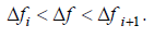
The frequency selectivity of a radio receiver is mainly determined by the selectivity of its narrowest-band part - the IF amplifier. The most commonly used model of receiver selectivity at the IF represents the IF amplifier's frequency response S(Δf ) as a piecewise-linear function of the logarithm of the frequency offset

where S(Δf ) - signal attenuation at offset Δf relative to the center frequency of the IF amplifier;
i- the segment number of the frequency-response approximation;
Si - the slope of the i -th approximation segment, dB/decade;
Δfi - the width of the i -th approximation segment;
This model is used when the values of the frequency characteristic are known at certain points spaced from the center frequency by an amount f . In practice, these are usually the 3, 20, and 60 dB levels. Let us denote the offsets at these levels as 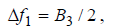

Then the frequency selectivity characteristic of the IF amplifier, corresponding to expression (7.1), has the form shown in Figure 7.6.
The curve is symmetric relative to the mean tuning frequency of the IF filters. The values of the coefficients Si (i=1,2) are determined in this case by the expressions:

In calculations related to evaluating the interference level for spurious reception channels, the shape of the frequency selectivity characteristic of the spurious channel is taken to be the same as for the main one.
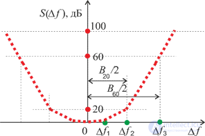
Figure 7.6 - Frequency selectivity characteristic
 30 MHz
 f0R
f0R  300 MHz
 f0R
f0R
Comments