
Lecture
By electromagnetic compatibility (EMC) of radio-electronic equipment is meant the ability of such equipment to function simultaneously under real operating conditions with the required quality when subjected to unintentional interference, without causing impermissible interference to other radio-electronic equipment (REE).
The essence of the electromagnetic compatibility problem lies in ensuring the operation of REE under the conditions of a given electromagnetic environment (EME), without exerting impermissible influence on other equipment. Therefore, the main direction for solving this problem is reducing the level of radio interference – the primary factor degrading the conditions for normal operation of REE.
Overall, in the process of designing radio communication facilities, electromagnetic compatibility (EMC) is considered at three levels:
The first stage of solving the EMC problem involves a comprehensive analysis of the EME and the conditions for ensuring EMC, based on measurements and modeling.
The analysis of inter-system EMC aims to ensure the absence of mutual radio interference between the radio equipment of each specific radio system being put into operation and radio-electronic equipment for civilian and special purposes.
The analysis of intra-system EMC is carried out mainly during the design process and aims to ensure the absence of mutual interference for the radio equipment used in each specific set of REE. Intra-equipment EMC can also be considered a component of intra-system EMC, in which the conditions and causes of unintentional interference arising directly within the functional units and blocks that make up the REE are analyzed.
The analysis of site EMC aims to ensure EMC at the selected site and is carried out for all radio equipment installed there. This is a special area of EMC condition analysis that takes into account, in particular, a number of factors that were not considered in the analysis of inter-system and intra-system EMC:
The second stage of solving the EMC problem consists in ensuring compatibility conditions. Technical and organizational measures that contribute to solving this problem are usually distinguished here.
Technical measures are usually implemented at the level of individual REE and come down to improving equipment characteristics from the EMC standpoint. These mainly include measures such as reducing unwanted emissions from transmitters and increasing the interference immunity of receivers with respect to unintentional interference.
The most common of these are filtering, shielding, the creation of special interference protection circuits, increasing the dynamic range of REE paths, etc., which are usually implemented at the development stage.
Organizational measures are carried out at the level of a set of REE and come down to creating such a structure of the large radio system in question, under which effective use of the spectrum segment allocated for this set of REE is ensured, and requirements from the standpoint of quality of operation are satisfied.
Organizational measures can include issues of frequency-territorial allocation (FTA), radiation power control, REE operating time schedules, etc.
Shielding in electronics — is a method of protecting electronic devices and circuits from external electromagnetic interference (EMI), as well as preventing the radiation of their own interference outward.
An electric or magnetic field can induce parasitic currents in wires, interfere with the operation of microchips, radio modules, audio paths, etc. Shielding creates a barrier that reflects or absorbs these fields.
Electrostatic shielding
Protects against electric fields.
➜ A conductive material is used (copper, aluminum, foil, metal mesh).
➜ Example: coaxial cable braid, foil insulation around a signal wire.
Electromagnetic shielding (EMI shielding)
Protects against high-frequency alternating electromagnetic fields.
➜ Materials with high conductivity and small thickness are used.
➜ Used in radio-frequency devices, Wi-Fi modules, microprocessors.
Magnetic shielding
Protects against low-frequency magnetic fields (for example, from transformers).
➜ Ferromagnetic materials are required: permalloy, μ-metal, steel.
➜ Screens are made multilayer in order to «close» the magnetic field lines inside.
In audio equipment (to reduce hum and pickup).
In radio-frequency devices (Wi-Fi, GSM, GPS).
In cables (shielded wires).
In power supplies and microcontrollers (metal enclosures, shields on boards).
In medicine (MRI chambers are fully shielded from external EMI).
Metal enclosures or housings are used.
Shielded cables are used with the shield grounded at one end (to avoid «current loops»).
Signal and power circuits are routed separately.
Ferrite rings and filters are added.
A conductive coating (for example, graphite or copper) is applied to plastic enclosures.
Shielding is a sufficiently effective measure for protecting electrical equipment from interference and other electromagnetic influences. According to GOST 30372-95, shielding is defined as a method of attenuating electromagnetic interference by means of a screen having high electrical and (or) magnetic conductivity.
In electric power engineering, frequencies of 50 or 60 Hz are used. Their harmonics can be taken into account in the range up to about 1.5 kHz, when it comes to effects on power equipment (communication equipment will be discussed separately). The lightning spectrum is very wide, and interference to radio communication is observed up to a frequency of 30 MHz. Nevertheless, the peak of the lightning strike spectrum is around 500 Hz.
At low frequencies, the model proposed back by Faraday is suitable. The external electric field causes polarization within the thickness of the screen. As a result, electric charges of opposite sign to those on the outer surface appear on the surface inside the screen. Ultimately, the field from these charges compensates for the external electric field.
Shielding from a low-frequency magnetic field is due to the fact that, when the magnetic permeability coefficient of the screen material is much greater than 1 and the structure has sufficient thickness, the magnetic field lines pass through the screen without entering the space enclosed within it.
It is by no means necessary for a screen to be made of a solid sheet without holes. There can be holes in a screen. Moreover, it can be a cage made of electrically conductive material. Such a version of a screen is called a «Faraday cage». But the following condition must be observed: the linear dimensions of the holes, or the pitch between the mesh bars, must be smaller in linear size (ideally — much smaller) than the wavelength of the radiation from which shielding is being provided. Good electrical contact (ideally — welding) between the cage bars is also important.
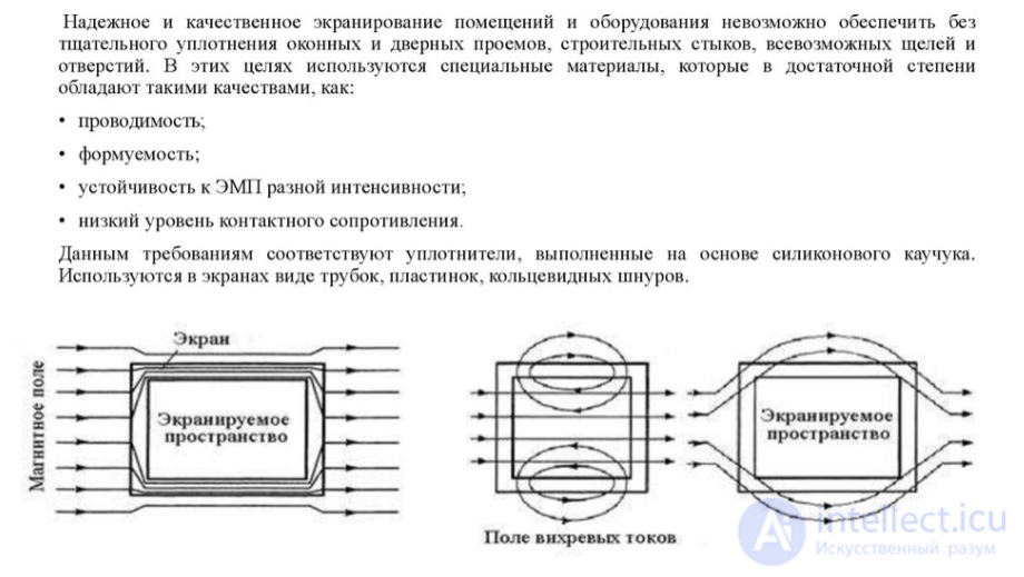
According to GOST R 51317.1.2-2007 (IEC 61000-1-2:2001) «Electromagnetic compatibility of technical equipment. Methodology for ensuring the functional safety of technical equipment with respect to electromagnetic interference», low frequencies with respect to shielding refer to frequencies below 9 kHz.
At frequencies above 9 kHz, a different model is used when considering the shielding phenomenon. If the processes are simplified to the utmost for ease of understanding, a screen at high frequencies works as follows. Under the action of external radiation, eddy currents arise in the screen. These currents create an electromagnetic field that compensates for the external influence.
Screen designs
It might seem that creating a high-quality screen with a high shielding coefficient is very simple — one needs to make a closed, electrically sealed contour (for example, a cube), and then it is easy to obtain a Ksh on the order of 100 dB or more. Unfortunately, in reality this is impossible, since holes will be needed for cable entry, ventilation, and equipment maintenance.
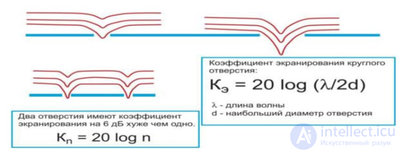
Every hole or slot in a screen comparable to 1/20 of the wavelength must be taken into account when planning a screen (fig. 3). Thus, for 1 GHz, a hole 1.5 mm in diameter will degrade the shielding coefficient to 40 dB; 1.5 cm — to 20 dB. As the number of holes increases, the shielding coefficient will degrade by Kn = 20 logn. Large holes and slots in a screen must be avoided.
Many small holes are better than one large one.
To create an effective screen it is necessary to:
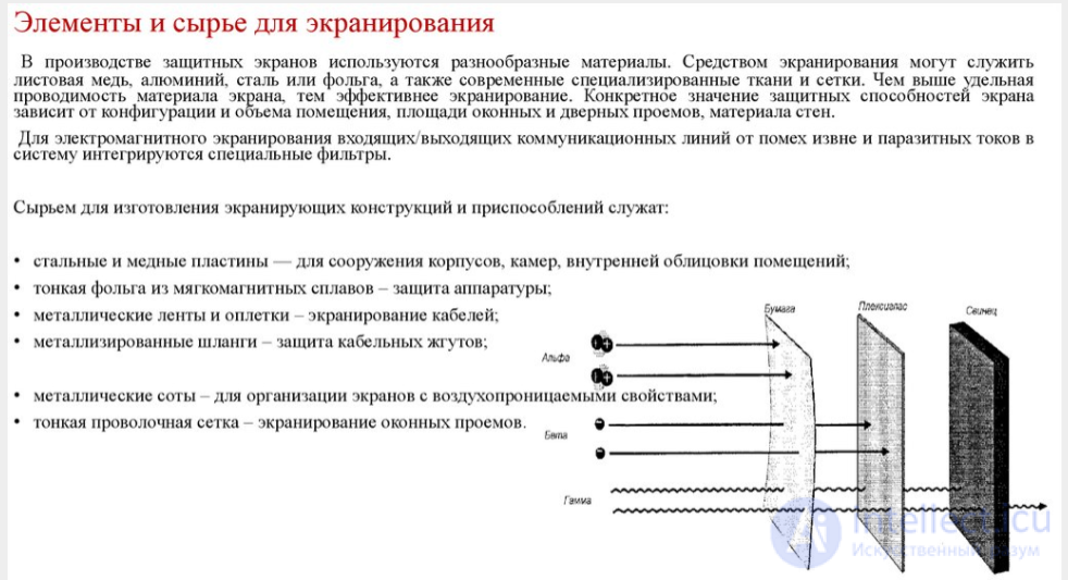
• select the material, its structure and thickness depending on the component of the electromagnetic field that needs to be shielded;
• if possible exclude any holes and slots and any other interruptions of electrical contact whose dimensions are comparable to 1/20 of the wavelength;
• use below-cutoff waveguides for ventilation and cable entry;
• use optical communication lines and feedthrough filters for signal and power input;
• use conductive gaskets or spring contacts to ensure contact around the perimeter of assembled structures;
• monitor the shielding coefficient of enclosures by conducting field measurements when possible.
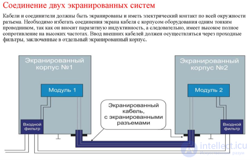
Some types of power cables have a shield. Most often, this shield is a metal tape wound around the insulation of the conductive cores. Variants of a shield made of thick wire, and a combination of thick wire and metal tape, are also encountered. Cable designs with shields made of conductive paper and conductive rubber are known. Very rarely one may encounter power cables with a shield made of thin-wire braid, although for signal cables such a design is quite common.
Cable shielding is applied in the following main cases:
Power cables laid in the ground and in water also often have metal armor. This armor is intended for the mechanical protection of the cable; nevertheless, it possesses shielding properties. According to PUE-7, clause 3.4.11, the presence of armor or a metal sheath is mandatory for a cable connecting the secondary winding of a transformer rated at 110 kV and above to the switchboard.
Prefabricated phase-segregated shielded busducts have found application at generation facilities and high-voltage substations. In these, the busduct of each phase is enclosed in a continuous, closed screen. The screen can be sealed, and at high voltages sulfur hexafluoride (SF6) gas is pumped into it. The screens are connected at one point to the site's grounding system.
The main functions performed by phase-segregated shielded busducts — reducing the interaction between conductors during external short circuits, as well as eliminating the heating, by induced currents, of nearby metal and reinforced-concrete structures. Other important functions of the screen — protecting the busduct from dust and moisture, and improving the safety of operation and maintenance.
Shielding issues aimed at protection against the secondary effects of lightning are addressed in SO 153-34.21.122-2003 «Instructions for the Design of Lightning Protection for Buildings, Structures, and Industrial Utilities». This document recommends using, where such a possibility exists, the metal reinforcement of a building as a screen.
When the reinforcement elements of a facility are electrically connected to one another, a «Faraday cage» is obtained. It protects equipment inside the building from the electromagnetic effects of a lightning strike. According to the instructions, the reinforcement must be connected to the building's lightning protection system.
In the case where there are shielded cables inside the protected space, their screens are connected to the lightning protection system at both ends and at the zone boundaries. When laying cables between buildings, if the cable's screen can withstand the lightning current, additional external shielding is not required. Otherwise, it is recommended to place the cable in a metal pipe or shielded duct for protection. The external screen or the cable's own screen is electrically connected at both ends to the common grounding busbars of the buildings.
At step-down stations and outdoor switchgear operating at 300 kV and above, the level of electromagnetic radiation from the equipment is hazardous to maintenance personnel. In connection with this, protective measures are applied in the form of metal mesh screens, magnetic screens made of materials with high magnetic permeability, and the like. Relevant recommendations are given in clause 4.2 of PUE-7.
In modern electric power engineering, a wide variety of communication devices are used. In particular, the digitalization of the power industry is impossible without them.
Electric power equipment and power transmission lines are a source of broadband interference. For the normal operation of communication systems installed at substations, it is necessary to ensure reliable shielding of low-current equipment. For this purpose, communication equipment is installed in metal cabinets connected to the site's common grounding system. Since even interference with a wavelength on the order of several centimeters can affect the operation of communication equipment, the cabinet design must not have large holes in it. When it is necessary to monitor the operation of communication equipment through an inspection window, the window is shielded with a conductive mesh, or conductive glass is installed in the window. These elements must have electrical contact with the cabinet.
Shielding of communication equipment in electric power engineering is regulated by the GOST IEC 6100 family of standards, as well as by organizational standards. This shielding must protect the communication equipment from spectral components above 9 kHz, i.e., it belongs to the category of high-frequency shielding. For high frequencies, the metal screen can be thin, but its high conductivity is important.
Instruments for Shielding
Electromagnetic radiation meters – allow determination of the interference level and the effectiveness of a screen.
Phase indicators and voltage indicators – used to monitor electrical parameters in shielded systems.
Phase sequence indicators – help during equipment setup to eliminate failures caused by EMI.
Devices for Shielding
Shielding meshes and wallpapers – create a barrier against radio-frequency waves.
Shielding covers and bags – protect mobile devices from external radiation.A Faraday bag completely blocks radio signals to protect gadgets, while shielding electromagnetic plasters and paints create a conductive barrier on walls, reducing the penetration of Wi-Fi, 5G, and other EM waves
Magnetic screens – used for protection against low-frequency magnetic fields.
Shielding clothing and fabrics – used in medicine and industry to protect personnel.
Substances and Materials for Shielding
Shielding paint and plaster – contain conductive fillers (graphite, metals), create a protective layer on walls.Operating principle: contain conductive fillers (graphite, carbon, metals), create a continuous barrier on the surface.Purpose: protection of premises from external electromagnetic waves (Wi-Fi, 5G, radio frequencies, high-voltage lines).
Shielding window film – reduces the penetration of radio-frequency waves.
Shielding fabrics and meshes (for example, YSHIELD HNG80) for windows and partitions
Metals (copper, aluminum, steel) – traditional materials for enclosures and cable shields.
Composite materials – modern coatings with a high shielding coefficient (up to 49 dB).
Comparison Table
| Category | Examples | Effectiveness | Application |
|---|---|---|---|
| Instruments | EMI meters, indicators | Monitoring and diagnostics | Setup and verification |
| Devices | Meshes, covers, clothing | Medium–high | Protection of devices and people |
| Substances | Paint, film, metals | High | Walls, windows, enclosures |
Important Points and Risks
An incorrect choice of material can reduce the effectiveness of shielding. For example, paint works only with continuous coverage without gaps.
Shielding reduces, but does not completely eliminate, EMI – for full protection several methods are often combined (screens + filters).
Standards (Tempest, EMC) define minimum requirements for shielding, especially in military and industrial electronics

Comments