
Lecture
Spurious emissions are quantitatively characterized by absolute, relative, or equivalent radiated power, which is expressed through field strength, power flux density, or, indirectly, through voltage or oscillation power in the antenna feeder at the frequencies of spurious emissions.
The absolute value of spurious emission power is expressed through the power flux density sp, or field strength Esp, and for feeder lines – through the average power Psp or voltage Usp in the feeder at the frequencies of spurious oscillations.
The relative value of spurious emission power rel – is the ratio of the power flux density sp or field strength Esp of the spurious emission to the power flux density 0 or field strength E0 of the fundamental emission, taken in the same units of measurement and expressed in decibels:
 (10.1)
The relative power levels Prel or voltage Urel of the spurious oscillation in the antenna feeder are respectively equal to:
 , (10.2)
where P0 and U0 – are the average values of power and voltage of the fundamental oscillation, expressed in the same units of measurement.
Often, instead of the power flux density, its spectral densityS is measured, the value of which is determined by the formula:
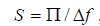 , where f – is the effective passband of the measuring device.
The absolute value of spurious emission power of radio transmitters is determined by measuring the field strength or power flux density created by the given spurious emission in the far field, or by measuring the voltage or power of spurious oscillations in the feeder line at the frequency of the spurious emission.
The first method is direct and allows the most accurate conclusions to be drawn about spurious emission power levels, i.e. to assess these emissions as interference from radio-electronic equipment to other radio-electronic equipment and services. In many cases this method (especially for decimeter, centimeter, and millimeter wave transmitters) is the only one available; however, it requires special measuring instruments and considerable time.
The second method is an indirect method of measuring spurious emission power; it is simple and more widely used, despite possible discrepancies between the measured oscillation power in the feeder line and the actual spurious emission power.
Measurements require a set of instruments that can be used to detect spurious emission frequencies, calibrate the measurement path, and measure the field strength. This set must provide measurements across the entire required frequency band.
A functional diagram of the setup for such measurements is shown in Fig. 10.1. It comprises a measuring antenna, high-frequency switches, attenuators, a tunable filter, a high-frequency signal generator, and a measuring receiver. The tunable filter serves to suppress the transmitter's fundamental emission at the input of the measuring receiver.
During measurements, the following are typically used: P6-series antennas with calibrated gain, D2- or D4-series attenuators with adjustable attenuation, and P5-series measuring receivers. The setup for measuring spurious emission power is placed on an open site along the axis of the main lobe maximum of the transmitter antenna's radiation pattern in the far field, avoiding the presence of nearby re-reflecting objects.
The nominal frequencies of emissions on harmonics and subharmonics are not difficult to determine by calculation; the frequencies of other types of spurious emissions are determined by tuning the measuring receiver. To exclude reception via spurious response channels of the measuring receiver, a bandpass filter tuned to the frequency of the detected spurious emission is additionally connected to its input, thereby avoiding reception via spurious channels.
The measurement setup shown in Fig. 10.1 allows direct or indirect (substitution method) measurement of the field strength of spurious emissions. Direct measurements take less time but may have significant errors, so to reduce errors (especially when communication receivers or selective microvoltmeters are used) measurements should be carried out using the substitution method.
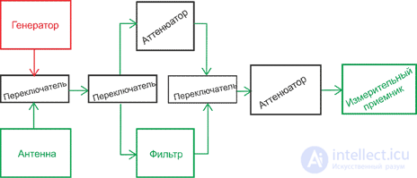
Figure 10.1 - Diagram of the measurement setup for spurious emission measurements
To carry out direct measurement of the field strength at each detected spurious emission frequency, the high-frequency path is first calibrated using a signal generator tuned to the spurious emission frequency, determining the path attenuation coefficient K .
After that, as indicated in the instrument's manual, the field strength of the spurious emission is measured using the measuring receiver Erx. The sought field strength value Esp, taking into account the attenuation in the measurement path, is equal to
Esp = Erx / K . (10.3)
This method measures the field strength of spurious emissions at frequencies significantly separated from the fundamental emission frequency. When measuring intermodulation, combination, and parasitic spurious emissions, whose frequencies lie within 10...15% of the fundamental emission frequency, the measurement results will be affected by the attenuation of the bandpass filter tuned to the fundamental emission frequency. To reduce the error in this case, the measurement is carried out using the substitution method.
For these measurements, the measuring receiver is first tuned to the frequency of the spurious emission. By adjusting the attenuator's attenuation, the indicator reading is made to exceed the receiver's inherent noise level by roughly a factor of two. Next, a signal generator tuned to the same frequency is connected to the receiver input, and its output signal level Ugen is adjusted so that the receiver's indicator reading equals the previously measured spurious emission level. Then the field strength is equal to
Esp = 2U gen / Seff K , (10.4)
where Seff – is the effective area of the measuring antenna at the spurious emission frequency.
The power flux density of spurious emissions is measured similarly, setting the receiver's IF amplifier passband to 1 MHz.
In this case, the measuring antenna is oriented toward the maximum of the received emission, and the attenuator's attenuation is adjusted so that the indicator reading falls at the middle of the scale. This value is recorded, and, without changing the attenuator setting, a signal generator is connected to the input of the measurement setup. By adjusting the output power Pgen at the spurious emission frequency, the previous indicator reading is reproduced. The sought power flux density of the spurious emission sp is calculated using the formula
 , (10.5)
where Kwg – is the power transmission coefficient of the waveguide path. Spectral. Measurements of the spectral power flux density of the spurious emission are carried out similarly, setting the measuring receiver's passband f to 100 kHz, and the calculation is performed using the formula:

The field strength, power flux density, and spectral power flux density of the fundamental emission are measured using the methods described, excluding the bandpass filter and adjusting the level of the measured signal with a variable attenuator. The relative power level of the spurious emission is determined using formula (10.1).
The methods discussed above for determining spurious emission power are quite complex and labor-intensive. Therefore, whenever possible, spurious emission power is determined by measuring the power of the corresponding oscillations in the feeder path.
At frequencies up to 1900 MHz, a single-wave method is used, employing directional couplers connected into the transmitter's feeder path. One of them is intended for measuring the incident wave power, the other for the reflected wave. A functional diagram of the setup for carrying out the measurements is shown in Fig. 10.2. In transmitters with a symmetrical output, couplers are connected into both feeders. The tunable filter serves to reduce the power of the fundamental oscillation entering the input of the measuring receiver.
 , (10.6)
where L01 and L02 - are the insertion (crosstalk) losses of the couplers at the frequency of the fundamental oscillation.
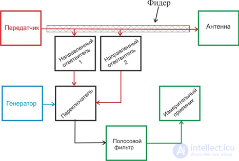
Figure 10.2 - Diagram of measurements of spurious oscillation power in the feeder
After that, the measuring receiver is tuned to the frequency of the selected spurious oscillation, and, similarly to the above, measurements are made of the spurious oscillation power Psp , going from the transmitter to the antenna
 , (10.7)
where Lsp1 and Lsp2 are the insertion losses of couplers 1 and 2, and Psp.inc and Psp.refl are the incident and reflected wave powers of the spurious oscillation in the feeder. The relative level of the spurious oscillations is determined using formulas (10.2).
For low-power transmitters, it is convenient and simple to determine the spurious oscillation power from the power dissipated in a broadband resistive load or antenna equivalent connected to the transmitter output. A functional diagram of the measurements is shown in Fig. 10.3.
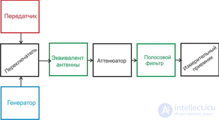
Figure 10.3 - Diagram of measurements of spurious oscillation power
The measurement is carried out using the substitution method, having first determined the frequencies of the spurious oscillations. The spurious oscillation power is determined by measuring the voltage U a ,created by the transmitter across the antenna equivalent, starting from the lowest frequencies. Knowing the resistance of the resistive load or antenna equivalent Ra ,the spurious oscillation power is calculated using the formula:
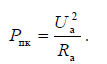 . (10.8)

Comments