
Lecture
The parameters that determine the susceptibility of a radio receiver include the sensitivity of the main and spurious reception channels, selectivity, and nonlinear effects such as blocking, cross-modulation, intermodulation, and others.
The main reception channel is the frequency band intended for receiving the wanted signal. The frequency selectivity characteristic of the main channel of a superheterodyne radio receiver is formed and determined mainly by the narrowband filters of the IF amplifier stages, while for direct-amplification receivers it is determined by the resonant circuits of the input stages.
Spurious reception channels lie outside the main reception channel; within the band of these channels, interference can penetrate to the output of the radio receiver. In addition, a receiver has adjacent channels whose bands are contiguous with the main reception channel. The bandwidth of the adjacent channels and their center frequencies correspond to the frequency allocation adopted for the given service.
The sensitivity of a radio receiver is its ability to provide reception of weak signals in the absence of external interference with the required quality. The sensitivity of a radio receiver is usually characterized by several parameters: real sensitivity, limiting sensitivity, and sensitivity limited by gain or by internal noise or interference.
The functional diagram of the measurement setup used to measure real sensitivity is shown in Figure 11.1.
The generator produces a test-signal voltage with a carrier frequency equal to the receiver's tuned frequency, modulated at 1000 Hz with a modulation depth of 30%. The antenna equivalent is needed so that the generator voltage ugs at the receiver input is the same as would result from a real external antenna exposed to a signal with field strength E , i.e., ugs Eheff
Bandpass filter 1, tuned to the modulation frequency of 1000 Hz, is needed to extract the test signal, while bandpass filter 2, covering 280...14000 Hz, is used to extract the noise within the receiver passband.
During the measurements, the generator is first tuned to the frequency being measured, and its output voltage is set equal to the receiver's rated real sensitivity. The receiver is then tuned to the generator's frequency, and the gain is set to provide the rated output signal power with bandpass filter 1 switched on.
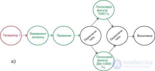
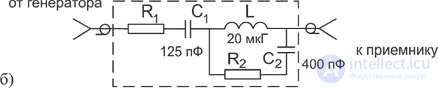
Figure 11.1– Functional diagram of the setup for measuring receiver sensitivity (a) and the schematic diagram of the antenna equivalent (b)
By changing the generator's output voltage in steps, starting from the minimum, the output voltage Uc is measured.
Then the generator's modulation is switched off, bandpass filter 2 is switched on, and the noise voltage Un at the receiver output is measured.
From the data obtained, the dependence of the ratio Uc /Un on the voltage at the receiver input Uin is plotted. The real sensitivity of the receiver is taken as Uin at the specified signal-to-noise ratio (20 dB for LF, MF, and HF receivers and 26 dB for higher-frequency receivers).
The real sensitivity of receivers with a magnetic antenna is determined using a standard-field generator (Fig. 11.2), which creates the required field strength at the location of the receiver's magnetic antenna.
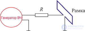
Figure 11.2 - Functional diagram of the standard-field generator
The square loop of the standard-field generator contains a single turn of copper wire 4...5 mm in diameter with dimensions of 380x380 mm. The resistance of resistor R is selected to equal the resistance of the external voltage divider of the RF signal generator that is excluded during the measurement.
In this case, in the measurement setup shown in Fig. 11.1, the signal generator and the antenna equivalent are excluded. During the measurements, the loop of the standard-field generator is placed at a distance of 1 m from the receiver. The generator's output voltage is adjusted so that the field strength corresponds to the receiver's real sensitivity, with the receiver's magnetic antenna oriented for maximum output signal, and the gain set to correspond to the rated output power.
By changing the generator's output voltage Ug in steps, the signal voltage is measured
Uc and noise Un at the receiver output using the method described above. From the data obtained, the dependence of the ratio Uc /Un on the field strength E is plotted, which is determined by the formula
E = 8Ug / R (µV/m),
where Ug – voltage at the output of the signal generator, µV;
R – resistance of the standard-field generator's resistor, Ohm.
The real sensitivity of a receiver with a magnetic antenna is determined from the plotted graph for the specified signal-to-noise ratio at the receiver output.
Sensitivity measurements of television receivers are performed separately for the sound channel and the picture channel. The methodology for such measurements differs somewhat from that described above.
Recall that the selectivity of a receiver is its ability to extract the wanted signal from the entire set of electromagnetic oscillations forming the field in the area of the receiver's antenna. There are single-signal and multi-signal methods for evaluating frequency selectivity.
The single-signal method is used to evaluate a radio receiver's selectivity under the assumption that the simultaneous action of interference and the wanted signal corresponds to the sum of the effects of each acting separately. For a radio receiver operating in a linear (or nearly linear) mode, this method gives a result close to the real one.
Measurement of the frequency selectivity of a radio receiver by the single-signal method is performed using a setup whose functional diagram is shown in Fig. 11.3.
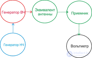
Figure 11.3 - Setup for measuring selectivity by the single-signal method
The RF generator must cover the entire frequency range of the receiver under test and have a tuning range from 0.5 fl to 8...10 fh, where fl and fh are the lower and upper boundaries of the radio receiver's frequency range.
This generator must be capable of internal modulation of the measurement signal's carrier at a frequency of 1000 Hz with a modulation depth of 30% (or modulation is performed using an external LF generator 2).
When measuring susceptibility via adjacent and spurious reception channels by the single-signal method, it is necessary to determine the rated input voltage Uin rated at which the rated output voltage Uout rated is provided on the main reception channel, as well as the voltage at the frequency of the non-main channel being measured at which this rated output voltage is provided.
To do this, generator 1 is tuned to the frequency of the main reception channel, modulation is switched on, and the output signal level of this generator is set equal to the receiver's sensitivity Uin rated . The receiver's gain is then set such that the rat-
ed output voltage Uout rated is provided.
Without changing the receiver's gain, passband width, or tuning, generator 1 is tuned to the frequency of the selected spurious reception channel. By increasing the output power of generator 1, the previously fixed level of the rated output voltage Uout rated is reached, while determining the output voltage of the generator Uin sc.
The susceptibility of the radio receiver at the frequency of the selected spurious reception channel sc is calculated using the formula:

The susceptibility of television receivers via adjacent television channels, the image channel, and the intermediate-frequency channel is measured by a similar method.
For a more accurate evaluation of a radio receiver's frequency selectivity, taking into account the inevitable nonlinear processes under the simultaneous action of the wanted signal and interference, multi-signal methods are used. In this case, the frequencies of the radio interference may or may not coincide with the frequencies of the main and spurious reception channels, and the interference levels can reach values at which the receiver exhibits blocking, cross-modulation, and intermodulation processes.
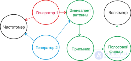
Figure 11.4 - Functional diagram of measurements using the two-signal method
When measuring cross-modulation distortion in an AM signal receiver, generator 1 (the wanted-signal generator) is unmodulated and tuned to the frequency of the main reception channel. Generator 2 (the interference generator) is detuned relative to the receiver's operating frequency, and its frequency lies outside the main reception channel. This generator is modulated by a sinusoidal oscillation at a frequency of 1000 Hz with a modulation factor of 0.3. At a given level of the interfering signal and a fixed detuning, the output signal level is measured. The modulation of the interference generator is then removed and modulation of the wanted signal is switched on. The modulation factor of generator 1 is varied until the previous output signal level is obtained.
For interference with the selected amplitude, modulation depth, and detuning, the resulting value of the modulation factor corresponds to the cross-modulation factor
mcm . The cross-modulation distortion factor is defined as the ratio of the measured cross-modulation factor to the modulation factor of the wanted signal mc
kcm = mcm / mc .
Cross-modulation distortion in FM receivers is measured in a similar manner.
When measuring the blocking interference level, generator 1 is tuned to the frequency of the main reception channel and the output level is set to 10 µV. The rated output level is set in the receiver under test. The measurement is performed with the interference frequency detuned by ± 20 kHz.
To do this, after setting the minimum output signal level of the interference generator, the frequency of generator 2 is first set 20 kHz above the receiver's tuned frequency, and the output voltage of this generator is increased until the wanted signal level at the output decreases by 3 dB. This generator voltage value is recorded.
This measurement is then repeated with generator 2 tuned to a frequency 20 kHz below the receiver's tuned frequency. The blocking interference level is determined in decibels from the smallest of the obtained output level values of generator 2 relative to 1 µV.
When measuring the level of interference causing intermodulation, the receiver is tuned to the frequency of generator 1, which is used to set the voltage at the receiver input equal to 10 µV and the rated output voltage. Interference is then simulated using generator 1 and generator 2, whose frequencies f1 and f2, after conversion, form various combinations equal to the receiver's tuned frequency or the intermediate frequency.
After setting equal output levels of the interference generators, they are increased until the output signal level reaches the previously established rated value. The intermodulation interference level is determined from the smallest output level value of generators 1 and 2 among all frequency-combination variants, in decibels relative to 1 µV.

Comments