
Lecture
Direction finding (DF), radio direction finding (RDF), or radiogoniometry — the use of radio waves to determine the direction to the source of a radio signal. The source may be a cooperating radio transmitter, a random source, a natural source of a radio signal, or an illegal or hostile system. Radio direction finding differs from radar in that each receiver determines only the direction; a radar system usually also indicates the distance to the object of interest, as well as the direction. By the method of triangulation the location of a radio signal source can be determined by measuring its direction from two or more points. Radio direction finding is used in radionavigation for ships and aircraft, to locate distress transmitters during search-and-rescue operations, for wildlife tracking and for detecting illegal or interfering transmitters. During World War II, radio direction finding was used by both sides to locate and direct aircraft, surface ships, and submarines.
RDF systems can be used with any radio source, although very long wavelengths (low frequencies) require very large antennas and are generally used only in ground-based systems. Nevertheless, these wavelengths are used for maritime radionavigation, since they can propagate over very great distances «beyond the horizon», which is valuable for ships, where the line of sight may be only a few tens of kilometers. For airborne use, where the horizon can extend for hundreds of kilometers, higher frequencies can be used, allowing much smaller antennas. Automatic direction finder equipment, which could be tuned to radio beacons called non-directional beacons or commercial AM-broadcasters, was a feature of most aircraft in the 20th century, but is now gradually being phased out. [ 1 ]
For the military, radio direction finding (RDF) is a key tool of signals intelligence. The ability to locate an enemy transmitter's position was invaluable since the time of the First World War and played a key role in the Battle of the Atlantic in World War II. It is estimated that advanced British radio direction-finding systems «Huff-Duff» were directly or indirectly responsible for 24% of all submarines sunk during the war. Modern systems often use phased antenna arrays for rapid beamforming and obtaining highly accurate results, and are part of a larger complex of electronic warfare assets.
Early radio direction finders used mechanically rotating antennas that compared signal levels, and several electronic versions of the same concept later appeared. Modern systems use comparison of phase or Doppler methods, which are generally easier to automate. Early British radiolocation stations were called RDF, which is often described as a deception. In fact, Chain Home systems used large RDF receivers to determine direction. Later radar systems generally used a single antenna for both transmission and reception, and determined direction from the direction in which the antenna was pointed. [ 2 ]
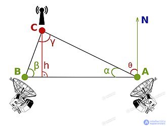 Diagram of radio triangulation using two direction-finding antennas (A and B)
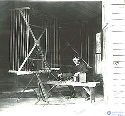
The first experiments in the field of radio direction finding (RDF) were carried out in 1888, when Heinrich Hertz discovered the directionality of an open wire loop used as an antenna. When the antenna was pointed at the signal, it provided maximum gain, and zero gain when aligned along the direct path. This meant there was always an ambiguity in the signal's location: the output was the same whether the signal was in front of the antenna or behind it. Later, experimenters also used dipole antennas, which worked the opposite way, achieving maximum gain at a right angle and zero gain along the direct path. RDF systems using mechanically rotated loop or dipole antennas became widespread by the early 20th century. The best-known examples were patented by John Stone Stone in 1902 (US patent 716,134) and by Lee de Forest in 1904 (US patent 771,819), among many others.
By the early 1900s, many experimenters were looking for ways to use this concept to locate a transmitter. Early radio systems usually used medium and long wave signals. Long-wave signals, in particular, had good long-distance transmission characteristics due to limited interaction with the ground, and thus provided excellent ground-wave propagation along a great-circle path , directed straight at the transmitter. Methods for performing RDF on long-wave signals were an important area of research in the 1900s and 1910s. [ 3 ]
Antennas are generally sensitive to signals only when their length is a significant fraction of a wavelength or more. Most antennas have a length of at least 1/4 wavelength, most often 1/2 — a half-wave dipole is a very common design. For use on long waves, this led to loop antennas tens of feet long on each side, often with more than one loop connected together to improve the signal. Another solution to this problem was developed by Marconi in 1905. It consisted of a series of horizontal wires or rods arranged to point outward from a common central point. A movable switch could connect opposite pairs of these wires, forming a dipole, and by rotating the switch, the operator could search for the strongest signal. [ 4 ] The U.S. Navy partially overcame this problem by mounting antennas on ships and sailing them in a circle. [ 5 ] Such systems were bulky and impractical for many applications. [ 6 ]
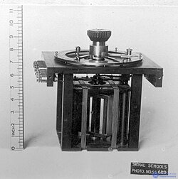
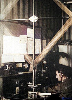
A key improvement to the direction-finder concept was proposed by Ettore Bellini and Alessandro Tosi in 1909 (US patent no. 943,960). Their system used two such antennas, usually triangular loops, arranged at a right angle. Signals from the antennas were fed into coils wound on a wooden frame about the size of a drink can, where the signals were reproduced in the region between the coils. A separate loop antenna placed in this region could then be used to determine direction without moving the main antennas. This made the radio direction finder practical enough that it soon came into wide use for navigation, often as the first available form of air navigation, with ground stations homing in on an aircraft's radio receiver. Bellini-Tosi direction finders saw widespread use from the 1920s through the 1950s.
Early radio direction finding (RDF) systems were useful mainly for long-wave signals. These signals can travel very long distances, which made them useful for long-range navigation. However, unexpected difficulties arose when the same technique was applied to higher frequencies, due to the reflection of high-frequency signals from the ionosphere. An RDF station could now receive the same signal from two or more directions, especially during the day, which created serious problems when trying to determine location. This led to the appearance in 1919 of the Adcock antenna (British patent No. 130490), which consisted of four separate monopole antennas instead of two loops, eliminating the horizontal components and thereby filtering out sky waves reflected from the ionosphere. Adcock antennas were widely used with Bellini-Tosi detectors starting in the 1920s.
In 1931 the US Army Air Corps tested a primitive radio compass that used commercial broadcast stations as a beacon. [ 7 ]
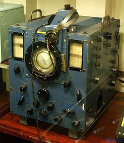
A significant improvement to the radio direction finding (RDF) method was proposed by Robert Watson-Watt as part of his experiments on locating lightning strikes to indicate the direction of thunderstorms to sailors and pilots. He had long worked with conventional RDF systems, but they were difficult to use because of the fleeting nature of lightning signals. He initially proposed using an oscilloscope to display these signals almost instantaneously, but could not find one while working at the Meteorological Office. After the service relocated, at his new post at a radio research station he obtained an Adcock antenna and a suitable oscilloscope, and in 1926 he presented his new system.
Despite the public demonstration of the system and wide coverage of its measurements in Britain, its impact on the art of radio direction finding (RDF) appears to have been surprisingly modest. Development of the system remained limited until the mid-1930s, when various British forces began large-scale development and deployment of these «high-frequency direction finding systems», or «Huff-Duff». To avoid radio direction finding, the Germans developed a method of transmitting short messages lasting less than 30 seconds, which was less than the 60 seconds a trained Bellini-Tosi system operator needed to determine direction. However, this was useless against Huff-Duff systems, which could determine direction accurately within seconds. The Germans only learned of this problem in the middle of the war and took no serious steps to address it until 1944. By that time Huff-Duff systems had contributed to roughly a quarter of all successful attacks on the U-boat fleet.
A number of developments in electronics during and after World War II led to significant improvements in methods of comparing signal phases. In addition, phase-locked loop (PLL) techniques made it easy to tune to signals, preventing them from drifting. Improved vacuum tubes and the adoption of transistors made it economical to use much higher frequencies, leading to the widespread use of VHF and UHF band signals. All these changes led to the emergence of new radio direction finding (RDF) methods and their much broader application.
In particular, the ability to compare signal phases led to the creation of the phase direction finder, which is perhaps the most widely used technique today. In this system the loop antenna is replaced with a single square ferrite core with loops wound around two perpendicular sides. Signals from the loops are fed into a phase-comparison circuit, whose output signal phase directly indicates the signal direction. By feeding this signal to any display and synchronizing it with a PLL, the direction to the broadcaster can be displayed continuously. Operation of the system is reduced solely to tuning to the station and is so automated that such systems are usually called automatic direction finders.
Other systems requiring greater precision were also developed. Pseudo-Doppler radio direction finders use a number of small dipole antennas arranged in a ring, with electronic switching to rapidly select the dipoles fed to the receiver. The resulting signal is processed and reproduces an audio tone. The phase of this audio tone, relative to the antenna's rotation, depends on the signal direction. Doppler direction finders have largely replaced the Huff-Duff system for locating rapidly fading signals.
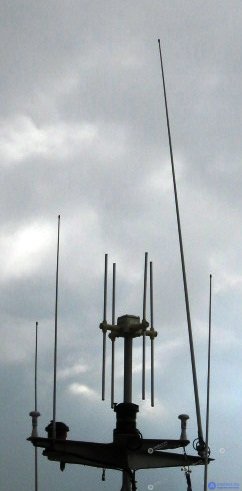
Various radio direction finding procedures for determining position at sea are no longer part of the GMDSS maritime safety system, in effect since 1999. The distinctive crossed-loop antenna with an attached auxiliary antenna is now found only on the signal masts of some older vessels, since it causes no interference there and its removal would be too costly.
Modern positioning methods, such as GPS, DGPS, radar, and the now-obsolete Loran C system, make use of radio direction finding, which is imprecise for modern tasks.
Radio direction finding networks also no longer exist. [ 8 ] However, rescue vessels such as RNLI lifeboats in the UK, and search-and-rescue helicopters, carry direction-finding receivers for marine VHF signals and 121.5 MHz homing signals built into EPIRB and PLB beacons, although modern GPS-EPIRBs and AIS beacons are gradually replacing them.
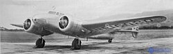
A radio direction finder ( RDF ) is a device for determining direction, or bearing , to a source of radio signal. The process of measuring direction is known as radio direction finding or sometimes simply direction finding ( DF ). Using two or more measurements from different locations, the location of an unknown transmitter can be determined; or, using two or more measurements of known transmitters, the location of a vehicle can be determined. RDF is widely used as a radionavigation system, especially on ships and aircraft.
Radio direction finding (RDF) systems can be used with any radio source, although the size of the receiving antennas depends on the wavelength of the signal; very long wavelengths (low frequencies) require very large antennas and, as a rule, are used only in ground-based systems. Nevertheless, these wavelengths are very useful for maritime navigation, since they can travel very long distances and «over the horizon», which is valuable for ships, when line of sight may be only a few tens of kilometers. For aircraft, where the horizon at altitude can extend for hundreds of kilometers, higher frequencies can be used, which allows for much smaller antennas. An automatic direction finder, often able to tune to commercial AM broadcast transmitters, is a feature of nearly all modern aircraft.
For the military, RDF systems are a key component of signals intelligence systems and methodologies. The ability to locate an enemy transmitter has been invaluable since the First World War and played a key role in the Battle of the Atlantic in the Second World War . It is estimated that advanced British «Huff-Duff» systems were directly or indirectly responsible for 24% of all U-boats sunk during the war. [ 9 ] Modern systems often use phased antenna arrays for fast beamforming and highly accurate results. As a rule, they are integrated into a broader suite of electronic warfare equipment.
Several different generations of Doppler direction finding (RDF) systems have been used over time, based on new developments in electronics. Early systems used mechanically rotating antennas that compared signal levels from different directions, followed later by several electronic versions of the same concept. Modern systems use comparison of phase or Doppler methods, which are generally easier to automate. Modern pseudo-Doppler direction finding systems consist of several small antennas mounted on a circular board, with all signal processing performed in software.
Early British radar stations were also called RDF, which was a deception tactic. However, the terminology was not inaccurate; the Chain Home system used separate omnidirectional transmitters and large RDF receivers to determine target locations. [ 2 ]
One type of direction finding uses a directional antenna, which is more sensitive in some directions than in others. Many antenna designs have this property. For example, a Yagi antenna has a fairly pronounced directivity, so the source of a signal can be located by pointing it in the direction where the maximum signal level is achieved. Since the directivity may be quite broad, large antennas may be used to improve accuracy, or signal-suppression techniques may be used to improve angular resolution.

The simplest form of directional antenna is the loop antenna. It consists of an open loop of wire on an insulating frame or a metal ring, which forms the loop element itself; the loop diameter is often a tenth of a wavelength or less at the target frequency. Such an antenna is least sensitive to signals perpendicular to its surface, and most receptive to signals arriving edge-on. This is due to the phase of the received signal: the difference in electrical phase along the edge of the loop at any given moment causes a difference in the voltages induced on the two sides of the loop.
Rotating the plane of the loop so that it «faces» the signal, so that the phases of the incoming signal are the same across its whole perimeter, will not cause current to flow in the loop. Thus, simply rotating the antenna to find a minimum of the desired signal will yield two possible directions (forward and backward) from which the radio waves may be arriving. This is called a null of the signal, and it is used instead of the direction of the strongest signal, because small angular deviations of the loop antenna from its null positions cause much sharper changes in the received current than similar changes in direction around the orientation for the strongest signal. Because the null direction gives a sharper indication of signal direction — the null is «sharper» than the maximum — in the case of a loop antenna the null direction is used to determine the location of the signal source.
A «sense antenna» is used to resolve the two possible directions; a sense antenna is an omnidirectional antenna configured to have the same sensitivity as the loop antenna. By adding the constant signal from the sense antenna to the varying signal from the loop antenna as it rotates, there is now only one position during a 360° rotation of the loop at which the current is zero. This acts as a phase reference point, allowing the correct null-current point to be identified and removing the 180° ambiguity. A dipole antenna has similar properties to a small loop, although the direction of its current null is not as «sharp».
The Yagi-Uda antenna is widely known as an ordinary television antenna for VHF or UHF band use. A Yagi antenna uses several dipole elements, including a «reflector» and «directors». The «reflector» is the longest dipole element, which blocks nearly all of the signal arriving from behind, so a Yagi antenna has no ambiguity in signal direction: the maximum signal occurs only when the narrowest end of the antenna is pointed toward the direction from which the radio waves are arriving. With a sufficient number of shorter «director» elements, the maximum directivity of a Yagi antenna can approach the sharpness of the null of a small loop antenna.
For even higher frequencies, such as millimeter waves and microwaves , one can use parabolic antennas or «dishes» . Dishes have high directivity, because the parabolic shape focuses received signals at a very narrow angle onto a small receiving element mounted at the focus of the parabola.
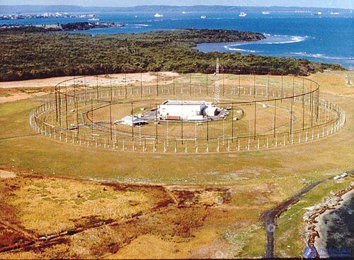
For high-precision direction-finding systems, more complex methods are usually used, such as phased antenna arrays. Modern systems are called goniometers by analogy with the direction-finding circuits of the Second World War era, which were used to measure direction by comparing the difference in signals received by two or more matched reference antennas, and were used in early signals intelligence (SIGINT). A modern helicopter-mounted direction-finding system was developed by ESL Incorporated for the US government as early as 1972.
Time-difference-of-arrival methods compare the time a radio wave arrives at two or more different antennas and use this information to determine the direction of arrival. This method can use mechanically simple, fixed, omnidirectional antenna elements connected to a multichannel receiving system.

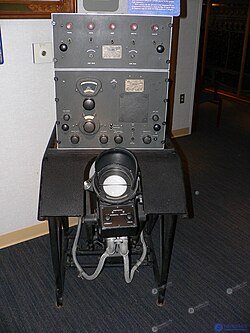
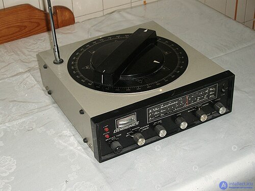
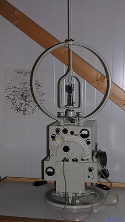
One method of radio direction finding is based on comparing the signal strength of a directional antenna, pointed in different directions. This system was originally used by ground and marine radio operators by means of a simple rotatable loop antenna connected to a bearing indicator. It was later adopted for use on both ships and aircraft and saw wide application in the 1930s and 1940s. On aircraft before World War II direction-finding antennas were easily recognized by the round loops mounted above or below the fuselage. Later loop-antenna designs were enclosed in an aerodynamic teardrop-shaped fairing. On ships and small vessels, direction-finding receivers originally used large metal loop antennas similar to those on aircraft, but usually mounted on a portable battery-powered receiver.
When using a direction finder, the operator first tuned the receiver to the desired frequency, then manually rotated the loop, either by listening or by watching the S-meter, to determine the direction of the null point (the direction in which the given signal is weakest) of a long-wave (LW) or medium-wave (AM) radio beacon or station (listening for the null point is easier than listening for the peak signal, and usually gives a more accurate result). This null point was symmetrical and thus indicated both the correct heading in degrees, marked on the radio receiver's compass rose, and its opposite direction 180 degrees away. Although this information provided a baseline from the station to the ship or aircraft, the navigator still needed to know in advance whether he was east or west of the station, in order to avoid plotting a course 180 degrees in the wrong direction. By taking bearings to two or more radio stations and plotting the intersecting bearings on a chart, the navigator could determine the relative position of his ship or aircraft.
Later direction finders came to be fitted with rotating ferrite loop antennas, which made them more portable and less bulky. Some of these were later partially automated with a motorized antenna (ADF). A key breakthrough was the introduction of a secondary vertical whip, or «sense» antenna, which confirmed the correct bearing and allowed the navigator to avoid plotting the bearing 180 degrees opposite the actual course. The US Navy model SE 995 direction finder, which used a sense antenna, was employed during the First World War. [ 10 ] After World War II, many small and large firms manufactured direction-finding equipment for mariners, including Apelco , Aqua Guide, Bendix , Gladding (and its marine division, Pearce-Simpson), Ray Jefferson, Raytheon and Sperry . By the 1960s, many of these receivers were actually manufactured by Japanese electronics makers such as Panasonic , Fuji Onkyo and Koden Electronics Co., Ltd. In aviation, Bendix and Sperry-Rand were two of the largest manufacturers of radio and navigation equipment.
A single-channel direction-finding system uses a multi-antenna array with a single-channel radio receiver. This approach to direction finding has its advantages and disadvantages. Since only one receiver is used, the advantages are mobility and lower power consumption. Without the ability to observe each antenna simultaneously (as would be the case with multiple receivers, also known as N-channel direction finding), more complex operations must be performed at the antenna in order to feed the signal to the receiver.
Single-channel speech recognition algorithms fall into two main categories: amplitude comparison and phase comparison. Some algorithms may be hybrid, combining both approaches.
The pseudo-Doppler shift method — is a phase-based direction-finding method that estimates the bearing of the received signal by measuring the Doppler shift induced in the signal by sampling around the elements of a circular antenna array. The original method used a single antenna that physically moved in a circle, but the modern approach uses a multi-antenna circular array, with each antenna sampled sequentially.
The Watson-Watt method uses two pairs of antennas to compare the amplitude of the incoming signal. The popular Watson-Watt method uses an array of two orthogonal loops (magnetic dipoles) in the horizontal plane, often supplemented by an omnidirectional vertically polarized electric dipole to resolve 180° ambiguities.
The Adcock antenna array uses a pair of monopole or dipole antennas that compute the vector difference of the received signal at each antenna, so that only a single output signal is produced by each antenna pair. Two of these pairs are placed close together but oriented perpendicular to each other, which produces signals that can be called north–south (N–S) and east–west (E–W) signals, which are then fed to the receiver. At the receiver, the bearing angle is calculated by taking the arctangent of the ratio of the N–S to E–W signals.
The basic principle of the correlative interferometer is to compare the measured phase differences with the phase differences obtained for a direction-finding antenna system of known configuration at a known wave angle (a reference data set). This requires a non-collinear baseline consisting of at least three antenna elements (with omnidirectional reception characteristics). The comparison is carried out for various azimuth and elevation values of the reference data set. The bearing result is obtained through correlation and stochastic estimation, for which the correlation coefficient is maximal. If the direction-finding antenna elements have a directional radiation pattern, amplitude may also be included in the comparison.
As a rule, a correlative interferometer direction-finding system consists of more than five antenna elements. They are scanned one after another using a special switching matrix. In a multichannel direction-finding system, n antenna elements are combined with m receiver channels to improve system performance.
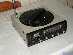
Radio direction finding, radio direction finder or RDF, was once a primary means of navigation in aviation. ( The term «range and direction» was used to describe the precursor to radar. [ 2 ] ) Beacons were used to mark the intersections of «airways» and to define takeoff and approach procedures. Because the transmitted signal carries no bearing or distance information, these beacons in the aviation world are called non-directional beacons, or NDB. Starting in the 1950s, these beacons were largely replaced by the VOR system, in which the bearing to the navigation aid is derived from the signal itself; therefore no special antenna with moving parts is required. Owing to their relatively low cost of acquisition, maintenance and calibration, NDBs are still used to mark the location of small airfields and important helicopter landing sites.
Similar beacons located in coastal areas are also used for maritime radio navigation, since almost every vessel was equipped with a direction finder (Appleyard 1988). Today (2008) very few marine radio-navigation beacons remain active, since ships have abandoned radio direction-finder navigation in favor of GPS navigation.
In the United Kingdom, for aircraft pilots in distress or experiencing difficulties, a radio direction-finding service is available on frequencies of 121.5 MHz and 243.0 MHz. This service is based on a number of direction-finding facilities located at civil and military airports and at some Her Majesty's Coastguard stations. [ 11 ] These stations can locate the aircraft and radio its position to the pilot.

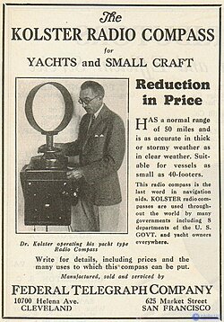
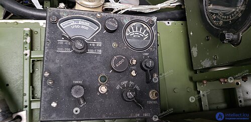
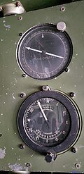
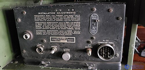
Radio transmitters for air and marine navigation are called beacons and are the radio analog of a lighthouse. The transmitter sends a signal in Morse code on a long-wave (150–400 kHz) or medium-wave (520–1720 kHz) frequency that includes a station identifier, used to confirm the station and its operating condition. Because these radio signals are transmitted in all directions (omnidirectional) throughout the day, the signal itself carries no directional information, and such beacons are therefore called non-directional beacons, or NDB.
Because the commercial medium-wave broadcast band falls within the frequency range of most radio direction finders, these stations and their transmitters can also be used for locating position. Although these commercial radio stations can be useful owing to their high power and location near large cities, the distance between the station and its transmitter can be several miles, which can reduce location accuracy when approaching the broadcasting city. A second factor is that some AM radio stations are omnidirectional during the day and switch to a lower-power, directional signal at night.
Earlier, radiolocation signals (RDF) were the primary form of navigation for aircraft and ships. Chains of beacons formed «airways» from airport to airport, while marine radio beacons (NDB) and commercial AM radio stations provided navigational assistance to small vessels approaching the shore. In the United States, commercial AM radio stations were required to transmit their station identifier once an hour for use by pilots and mariners as a navigational aid. In the 1950s, aviation NDBs were supplemented by the VOR system, in which the direction to the beacon can be extracted from the signal itself, hence the distinction from non-directional beacons. The use of marine NDBs in North America was largely displaced by the development of the systemLORAN in the 1970s.
Today, many NDB radio beacons have been decommissioned in favor of the faster and far more accurate GPS navigation systems. However, the low cost of ADF and RDF equipment, together with the survival of AM broadcast stations (as well as navigation beacons in countries outside North America), has allowed these devices to remain in service, mainly for use on small vessels as a supplement or backup to GPS.
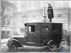
During the Second World War, significant efforts were directed at locating clandestine transmitters in the United Kingdom (Great Britain) by direction-finding methods. This work was carried out by the Radio Security Service (RSS, also known as MI8). Initially, in 1939, the British General Post Office set up three HF Adcock U-type direction-finding stations. With the declaration of war, MI5 and RSS expanded this network. One of the challenges in providing coverage over an area the size of Great Britain was installing enough direction-finding stations to receive signals reflected from the ionized layers in the upper atmosphere. Even with the expanded network, some areas remained inadequately covered, and for this reason up to 1,700 volunteer interceptors (radio amateurs) were recruited to detect illegal transmissions using ground waves. In addition to the fixed stations, RSS operated a fleet of mobile direction-finding vehicles throughout Great Britain. If a transmitter was detected by fixed direction-finding stations or volunteer interceptors, mobile units were dispatched to the area to home in on the source. High-frequency Adcock systems were used as the mobile installations.
By 1941, only a few illegal transmitters had been identified in Great Britain; these turned out to be German agents who had switched sides and were transmitting under MI5 control. Numerous illegal transmissions originating from German agents in occupied and neutral European countries were logged. This traffic became a valuable source of intelligence, so control of RSS was subsequently transferred to MI6, which was responsible for secret intelligence originating from outside Great Britain. Direction-finding and interception operations grew increasingly extensive and important up until 1945.
The Adcock HF stations consisted of four 10 m vertical antennas surrounding a small wooden operator's hut housing the receiver and a radio-controlled goniometer tuned for bearing determination. MF stations were also used, employing four antennas on 30 m guyed lattice towers. In 1941, RSS began experimenting with spaced-loop direction finders developed by Marconi and the National Physical Laboratory of Great Britain. They consisted of two parallel loops from 1 to 2 m square at the ends of a rotating beam 3 to 8 m long. The angle of the beam was combined with the readings of the radio-controlled goniometer to determine the bearing. The resulting bearing was significantly more accurate than that obtained with the U-shaped Adcock system, but ambiguities existed that hindered the installation of the 7 proposed spaced-loop systems. The operator of a spaced-loop system was stationed in a metal underground tank beneath the antennas. Seven underground tanks were built, but only two spaced-loop systems were installed, at Wymondham, Norfolk, and Weaverthorpe, Yorkshire. Problems resulted, and the remaining five underground tanks were fitted with Adcock systems. The rotating SL antenna was turned by hand, which considerably slowed successive measurements compared with rotating the goniometer dial.
In 1942, another experimental spaced-loop station was built near Aberdeen for the Air Ministry, in the form of a semi-underground concrete bunker. However, it too was abandoned owing to operational difficulties. By 1944, a mobile version of the spaced-loop station had been developed, which was used by RSS in France following the Allied landings in Normandy on D-Day.
During the Second World War, the American military used a shore-based version of the spaced-loop direction finder, known as «DAB». The loops were mounted at the ends of a beam housed inside a wooden hut, while the electronics were housed in a large cabinet with a cathode-ray display at the center of the beam, with all components supported on a central axis. The beam was rotated by hand by the operator.
In 1944, the Royal Navy commissioned a modification of shore-based high-frequency direction-finding stations for tracking submarines in the North Atlantic. Groups of five direction-finding stations were built, allowing the bearings from individual stations in a group to be summed and averaged. Four such groups were built in Great Britain: at Ford End (Essex), Goonhavern (Cornwall), as well as at Anstruther and Bowermadden (Scottish Highlands). Groups were also built in Iceland, Nova Scotia and Jamaica. The expected improvements were not realized, but subsequent statistical studies refined the system, and the groups at Goonhavern and Ford End continued to be used during the Cold War. The Royal Navy also used direction-finding equipment aboard ships assigned to anti-submarine warfare in an attempt to detect German submarines; for example, «Captain»-class frigates were fitted with a medium-frequency direction-finding antenna (MF/DF) (the antenna was mounted forward of the bridge) and a high-frequency direction-finding antenna (HF/DF, «Huff-Duff») of the FH 4 type (the antenna was mounted at the top of the main mast). [ 12 ]
A comprehensive reference on wireless direction finding during the Second World War was written by Roland Keen, who headed the RSS engineering department at Hanslope Park. The direction-finding systems mentioned here are described in detail in his 1947 book « Wireless Direction Finding» . [ 13 ]
At the end of the Second World War, a number of RSS radio direction-finding stations continued to operate into the Cold War period under the control of GCHQ, the British signals intelligence organization.
At present (2009), most direction-finding efforts in the United Kingdom are aimed at detecting unauthorized « pirate » FM broadcasts. A network of remotely controlled VHF direction finders, located mainly around major cities, is used. Mobile phone transmissions are also located using a direction-finding method based on comparing signal strength at surrounding local cell receivers. This method is often used as evidence in criminal proceedings in the United Kingdom and, almost certainly, for signals intelligence purposes. [ 14 ]
Emergency locator beacons are widely used on civilian aircraft and vessels. Historically, emergency locator transmitters transmitted only a tone signal and relied on direction finding by search aircraft to locate the beacon. Modern emergency beacons transmit a unique identification signal that may include GPS location data that help determine the precise location of the transmitter.
Avalanche transceivers operate on the standard frequency of 457 kHz and are designed to locate people and equipment buried under avalanches. Because the beacon power is very low, the directionality of the radio signal is determined by small-scale field effects [ 15 ], and detecting it can be quite challenging.
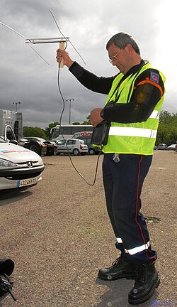
Locating radio-tagged animals by the method of triangulation — a widely used research technique for studying animal movement. This method was first used in the early 1960s, when radio transmitters and batteries became compact enough to be attached to wild animals, and it is now widely used in various wildlife studies. In most cases, tracking of wild animals fitted with radio transmitters is carried out by a field researcher using a portable radio direction finder. When a researcher wants to find a specific animal, its location can be determined by triangulation, by taking bearings to the transmitter from several points.
Phased array antennas and other advanced antenna technologies are used to track the launches of missile systems and their trajectories. These systems can be used for defensive purposes, as well as for gathering intelligence on the activities of missiles belonging to other countries. The same methods are used to detect and track ordinary aircraft.
Ground-based receivers can detect radio signals coming from distant stars or regions of ionized gas. Receivers in radio telescopes can determine the general direction of such natural radio sources, sometimes correlating their location with objects visible in optical telescopes. Precise measurement of the arrival time of radio pulses by two radio telescopes located at different points on Earth, or by the same telescope at different times as the Earth orbits the Sun, can also allow the distance to the radio source to be estimated.
Events organized by groups and organizations that involve the use of direction-finding skills to locate transmitters in unknown locations have been popular since the end of the Second World War. [ 16 ] Many of these events were originally held to practice direction-finding techniques for disaster response and civil defense, or to practice locating the source of radio-frequency interference. The most popular form of this sport worldwide is amateur radio direction finding (ARDF). Another form of the activity, known as « transmitter hunting », «mobile transmitter hunting» or «fox hunting», takes place over a more extensive geographic area, such as the metropolitan region of a large city, with most participants traveling by car while trying to locate one or more radio transmitters using direction-finding techniques.

Methods for direction finding at microwave frequencies were developed in the 1940s in response to the growing number of transmitters operating at these higher frequencies. This required the development of new antennas and receivers for direction-finding systems.
In naval systems, direction-finding capability became part of the electronic warfare (EW) suite, where the resulting bearing information supplements other signal identification processes. In aviation, the direction-finding system provides additional information for the radar warning receiver (RWR).
Over time, the need arose to improve the performance of microwave direction-finding systems in order to counter evasion tactics used by some operators, such as low probability of intercept (LPI) radars and covert data links .
In the early part of the century vacuum tubes (thermionic tubes) were widely used in transmitters and receivers, but their high-frequency performance was limited by transit-time effects. [ 20 ] : 192 [ 21 ] : 394 [ 22
продолжение следует...
Часть 1 Determining the direction of radio emission, radio direction finding
Часть 2 Amplitude-comparison DF - Determining the direction of radio emission, radio

Comments