
Lecture
Crystal (detector) receiver is the simplest, most basic type of radio receiver. It has no amplifying elements and requires no power source — it uses only the energy of the received radio signal.
The main function of a radio receiving device is to extract useful information from the received signal. In the simplest case, it is sufficient to demodulate the received signal. Such receivers are called crystal (detector) receivers and are used in the cheapest wireless communication devices. A block diagram of a crystal receiver is shown in Figure 1.

Figure 1. Block diagram of a crystal radio receiver
Note that even in such a simple circuit, an input matching network is required to match the antenna impedance to the input impedance of the diode detector. The detector used must be a circuit that extracts information from the useful signal. For an AM signal it must be an amplitude detector, for an FM signal a frequency detector must be used, and for digital modulation types a quadrature detector is usually used; however, because of the implementation features of frequency and quadrature detectors, such receivers are usually classified as direct-conversion receivers.
Crystal receivers are used in the simplest wireless devices, typically operating over short distances (no more than a few dozen meters). The main advantages of this circuit are its simplicity, small size and low cost, as well as the absence of a power source. The receiver circuit is powered entirely by the energy of the radio waves.
Among the drawbacks are the receiver's low sensitivity, which requires the use of significant transmitter power. The low frequency selectivity means that such radio links can only be used at a considerable distance from one another, or in rooms isolated from each other by metal shielding.
A half-wave diode rectifier is usually used as the detector in such circuits. The schematic diagram of such a receiver is shown in Figure 2.
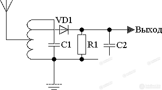
Figure 2. Schematic diagram of a crystal radio receiver
A single tuned circuit with taps on the inductor coil is used as the input device in this circuit. The taps on the coil serve to match the characteristic impedance of the circuit with the antenna impedance and the input impedance of the diode detector.

Comments