
Lecture
Real-Time Kinematic positioning ( RTK ) — is an application of geodetic surveying methods to correct common errors in modern satellite navigation systems (GNSS) . It uses measurements of the carrier phase of the signal wave in addition to the signal's informational content, and relies on a single reference station or an interpolated virtual station to provide corrections in real time, achieving centimeter-level accuracy (see DGPS ). With respect to GPS in particular, the system is usually called carrier-phase enhancement or CPGPS . It is used in topographic surveying , hydrographic surveying and unmanned aerial vehicle navigation .
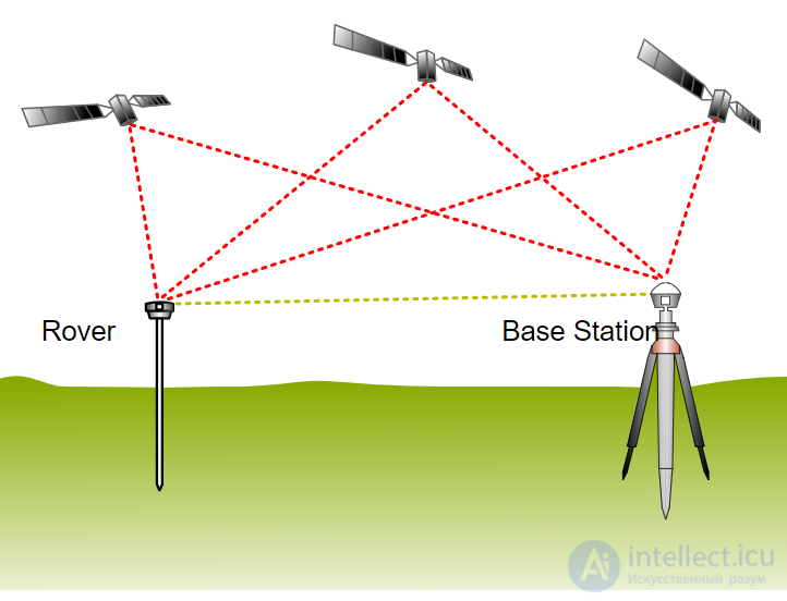
RTK concept
The distance between a satellite navigation receiver and a satellite can be calculated from the time it takes the signal to travel from the satellite to the receiver. To calculate the delay, the receiver must align the pseudorandom binary sequence contained in the signal with an internally generated pseudorandom binary sequence. Because the satellite signal takes time to reach the receiver, the satellite's signal sequence is delayed relative to the receiver's sequence. By progressively delaying the receiver's sequence, the two sequences eventually align.
The accuracy of the resulting range measurement is essentially a function of the receiver electronics' ability to accurately process the signal from the satellite, as well as additional sources of error such as unmodeled ionospheric and tropospheric delays, multipath propagation, and satellite clock and ephemeris errors .
RTK follows the same general concept, but uses the carrier of the satellite signal, ignoring the information content it carries. RTK uses a fixed base station and a rover to reduce the rover's position error. The base station transmits correction data to the rover.
As described in the previous section, the range to the satellite is essentially calculated by multiplying the carrier wavelength by the number of complete cycles between the satellite and the rover, and adding the phase difference. Determining the number of cycles is a nontrivial task, since the signals may be phase-shifted by one or more cycles. This results in an error equal to the error in estimating the number of cycles multiplied by the wavelength, which is 19 cm for the L1 signal. Solving this so-called integer ambiguity resolution problem yields centimeter-level accuracy. The error can be reduced using sophisticated statistical methods that compare C/A signal measurements and the resulting ranges between multiple satellites.
The improvement possible with this method is potentially very large, assuming a lock accuracy of 1%. For example, in the case of GPS, the coarse/acquisition (C/A) code broadcast on the L1 signal changes phase at 1.023 MHz, but the L1 carrier itself is 1575.42 MHz, changing phase more than a thousand times more often. Thus, a ±1% error in measuring the L1 carrier phase corresponds to a ±1.9 mm error in the baseline estimate.
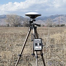
RTK setup
In practice, RTK systems use a single base-station receiver and several mobile devices. The base station relays the observed carrier phase, and the mobile devices compare their own phase measurements with those received from the base station. There are several ways to transmit the correction signal from the base station to the mobile station. The most popular way to achieve low-cost real-time signal transmission is to use a radio modem , typically in the UHF band . In most countries, specific frequencies are allocated specifically for RTK purposes. Most surveying equipment comes standard with a built-in UHF-band radio modem. RTK provides improved accuracy at distances of up to about 20 km from the base station.
This allows devices to calculate their relative position with millimeter accuracy, although their absolute position is only as accurate as the computed position of the base station. The typical nominal accuracy of these systems is 1 centimeter ± 2 parts per million (ppm) horizontally and 2 centimeters ± 2 ppm vertically.
Although these parameters limit the usefulness of the RTK method for general navigation, this method is ideal for tasks such as surveying. In this case, the base station is placed at a known survey location, often at a benchmark , after which mobile devices can create a highly accurate map by applying the correction relative to that point. RTK has also found application in auto-steering/autopilot systems, precision agriculture , machine control systems, and similar purposes.
RTK networks extend the usability of RTK to a larger area covered by a network of reference stations. Operational reliability and accuracy depend on the density and capabilities of the reference station network.
A network of continuously operating reference stations (CORS) — is a network of RTK base stations that broadcast corrections, typically over an Internet connection. In a CORS network, accuracy is improved because having multiple stations helps ensure correct positioning and protects against false initialization from a single base station.
A virtual reference network (VRN) can similarly improve accuracy without using a base station
Corrections can be transmitted in RTCM SC-104 format (message codes 3, 18-21, 32, 1003—1008 ), CMR and CMR+, RTCA, ATOM. The required transmission rate is 2400 bit/s or higher, and the transmission delay is no more than 0.5−2 seconds. Conventional DGPS was sufficient with rates of 200 bit/s and delays of up to 10 sec, whereas information streams in SSR format require considerably more.
Starting with version 3.0, the RTCM SC-104 standard includes the ability to transmit RTK corrections for the GLONASS system. Versions 2.3 and subsequent 3.x versions are not compatible, so they exist in parallel.
Version 3.1 supports various RTK-Network base station data formats (VRS, FKP and MAC), as well as SSR messages (precise ephemerides and clock drift parameters).
Version 3.2 (February 2013) adds Multiple Signal Messages (MSM). The MSM format allows a receiver to use all satellite systems. The messages include compact and full messages for pseudoranges, carrier phase measurements, carrier-to-noise ratio (standard and high resolution), and carrier phase measurement rate.
In October 2016, RTCM version 3.3 (designation RTCM 10403.3) was released, in which BeiDou (BDS) was added to the accepted messages for the GPS, GLONASS, Galileo and QZSS systems, and all previous 3.x version additions were merged.
RTCM formats are traditionally divided into two categories: Observation State Representation (OSR) and State Space Representation (SSR). These groups use different methods, delivery mechanisms and underlying technologies to solve the same problem
Compact Measurement Record (CMR) — a fairly old format that contains information only from GPS L1/L2 satellites. Developed by Trimble in 1992 as a method of transmitting code and carrier-phase correction data in a compact format from GPS base stations to GPS rovers for RTK GPS surveying.
CMR+ — Trimble's second generation of CMR. It has a more compact message structure than CMR. The GPS portion of this protocol was originally Trimble proprietary, but was later opened and became a widely used standard.
CMRx was developed in 2009 to support GNSS constellations that had undergone significant changes. The goal of CMRx was to improve initialization time, cover additional core GNSS constellations, handle new GNSS signals, and improve performance in urban environments and under «closed-sky» conditions.
RTX — a Trimble proprietary format that uses communication satellites to transmit RTK correction data to the rover, rather than ground radio stations or cellular networks. The data stream is in fact CMRx correction data. The improved data compression of CMRx is extremely important for a satellite system, since bandwidth on the satellite is quite expensive. As with CMRx, this is available only on Trimble receivers.
Technical Commission for Aeronautics (RTCA) — a format developed by the U.S. Radio Technical Commission for Aeronautics.
NCT — a proprietary correction data format from John Deere. In 1999, when precision agriculture was just beginning to develop, John Deere acquired the GNSS manufacturer NavCom. Today the company produces receivers for both agriculture and other industries. The format is proprietary and supported only by John Deere.
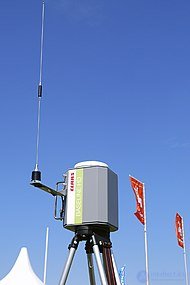
Single-base RTK
Single Base RTK — a base station operating in RTK mode, consisting of one reference receiver, a microprocessor and a VHF radio modem. It can be mobile for surveying purposes, or in rare cases stationary for navigation purposes. Coverage is limited to a local area of up to 40 km from a single station. As the distance from the base increases, the ability to resolve ambiguities decreases, which affects the position accuracy of the moving rover. Accuracy reaches, horizontally: 0.01 m +/-0.5 ppm, and vertically: 0.02 m +/-1.0 ppm . Or 12 mm horizontally and 60 mm vertically, at the maximum distance from the base.
Network RTK, or Multiple Reference Station — a mathematical model of a configuration combining 2 or more reference GNSS receivers (RR) into a network, connected via communication links (an IP address (internet) or GSM cellular links) into a single complex. The reference receivers continuously transmit their individual satellite observations to a server. The network software precisely resolves satellite ambiguities observed by the reference receivers (RR). The maximum distance between reference receivers is no more than 70 km from each other
The RTK-Network concept is applied when building Differential Correction Systems in 2 variants: geodetic Precision Positioning Systems (PPS) and Control and Correction Stations (CCS) for navigation systems. Both configurations require a central server (a powerful processor) to compute corrections and communication links to collect information. The RTK-Network concept makes it possible to model (predict) major errors over areas of different size and varying quality (accuracy).
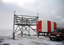
WAAS system CCS with 3 reference receivers
Control and correction stations, or measurement collection stations, are a complex of high-precision navigation equipment designed with a redundant configuration. Traditionally, a CCS contains 2 or more reference stations installed at points with known coordinates, which guarantees reliability and autonomy in the event of failures, and the trustworthiness of the collected information
Precision Positioning Systems, made up of reference stations, form a single network. Data received from the stations flow into a computing center that includes both the appropriate hardware and software. The reference stations' communication equipment ensures continuous transmission of data to the computing center, where it is automatically archived and converted to RINEX format. After the differential corrections are generated, the computing center's communication equipment transmits them to authorized users operating in RTK mode . Such systems are deployed in Germany, Switzerland, the Netherlands, France, Denmark, and Sweden. . In Russia, full coverage has been achieved for Moscow and Moscow Region, St. Petersburg and Leningrad Region, and Sverdlovsk and Samara Regions. the cities of Sevastopol and Kaliningrad (with their regions). 90% coverage is available in Krasnodar Krai, the republics of Crimea, Tatarstan, Udmurtia and Chuvashia, and Omsk, Voronezh, Kurgan and Rostov Regions. As of 2019, more than 6 major companies offering PPS services were present in Russia (RTK-Net , PrinNet , Topnet , SmartNet , eft-cors[ , SSTP BTI[ ), using equipment from various manufacturers. The networks compete and cooperate on an equal footing.
Today, RTK networks implement various methods for generating precise corrections, such as MAX and i-MAX, VRS or VBS, and FKP
MAX and i-MAX (Master-Auxiliary Corrections) The method is based on the concept of the same name, MAC (Master Auxiliary Concept), jointly proposed by Leica Geosystems and Geo++ in 2001. Individualized MAX (i-MAX) was developed to support older receivers that cannot receive MAX-type corrections.
The concept consists of correcting the rover's coordinates via the nearest (conditionally primary, master) station. This concept gives the rover greater flexibility — the rover can always track the RTK solution and change its calculations while in motion.
Correction information is collected from the network (several base stations tied to a single server), processed by specialized software, and delivered to the user. Thus, MAX and i-MAX corrections link the base receiver with the rover, and the baseline can be re-measured .
VRS (Virtual Reference Station) or VBS (Virtual Base Station) — the virtual base station method was developed by Terrasat in the late 1990s. Like the MAX methods, this method generates corrections by simulating RTK in single-base-station mode — the rover sends approximate coordinates of its own position (a GGA message) to the server, and the server automatically generates a conditional (virtual) base 10-15 meters from the rover, assigning a weight to each reference station as a function of distance to the work area (the receiver accepting corrections). A specialized software package then starts a mode generating corrections from the virtual station. The rover then begins working from the virtual station. As a result, a single set of differential corrections is obtained, optimized for the given work area. This does not guarantee measurement consistency, and repeated regeneration of base stations by switching the rover on and off leads to position jumps. However, VRS makes it possible to achieve sub-centimeter accuracy over relatively large distances — 50-70 km in real time, across a network that is uniform over the whole area
Advantages of VRS or VBS.
FKP (Flächen Korrektur Parameter, from German — «area correction parameter method»)) This method involves calculating differential corrections over the area covered by several base stations (the area of expected solutions), without accounting for the prior position of the mobile satellite receiver. A linear-area polynomial is used to provide the corrections. It relates to a surface defined as parallel to the WGS-84 ellipsoid at the height of the reference station, that is, at the pseudorange of the mobile rover. From the set of coordinates belonging to the surface sector (the area of expected solutions), those corresponding to the L1 and L2 carrier phase difference are selected, from which the pseudorange, corrected for position-dependent errors, can be calculated accordingly.[
In the late 1990s, the Research Group of Astronomy and Geomatics (gAGE) at the Technical University of Catalonia (UPC) proposed the Wide Area RTK concept to solve a number of problems. It is based on real-time carrier-phase ambiguity resolution, which makes it possible to extend local services to a wide scale (that is, to increase the coverage of baselines between the rover and the base station to 100 km), for both dual-frequency and multi-system receivers (single-frequency receivers are fundamentally excluded). The method is based on the optimal combination of precise ionospheric and geodetic models within a network of continuously operating reference stations. The main factor limiting the extension of RTK range beyond a few dozen kilometers is the differential ionospheric correction between the rover and the nearest GNSS reference station. Such correction hinders real-time ambiguity resolution, and consequently the maintenance of correspondingly precise navigation at the sub-decimeter level. That is, the main errors are eliminated. The main remaining source of error is the ionosphere and its correlations, mitigating which becomes the main problem to be solved, of negligible significance compared to the others. The method has been demonstrated on real data, but has not yet been deployed, despite the fact that it increases coverage to 500—900 kilometers from the base station and consequently requires 100—1000 times fewer receivers to cover a given region
Correction transmission is carried out over a radio channel (at frequencies of 410—470 MHz for most devices). The base can either be set up at a point (location) with known coordinates, or its coordinates can be determined autonomously, by averaging coordinates over a certain time interval (usually several minutes). In the second case, the work is performed by calibrating the work area against known points in the field software of the controller used to work with the rover receiver. The radio modems built into base receivers have a power of up to 4-5 W and are equipped with compact (up to 30 cm) antennas for operation over short distances. To increase the operating range, external radio modems with power up to 35-40 W are used, with a separate power supply and larger antennas (up to several meters), usually on a separate mount.
Advantages:
Disadvantages:
GSM communication can be provided through: the receiver's internal terminal, an external terminal connected to the receiver via RS-232, or through the field controller's terminal (relevant for the rover).
CSD (Circuit Switched Data). Correction transmission from the base station is performed directly, by the rover «dialing» the phone number of the SIM card installed in the GSM terminal of that base. It was popular until 2010, but after 2010 cellular operators gradually began discontinuing support for this service, leaving it available only on certain IoT-device plans.
Advantages:
Disadvantages:
NTRIP (Networked Transport of RTCM via Internet Protocol). Introduced in September 2004 by the German Federal Agency for Cartography and Geodesy (BKG) and the Dortmund University Department of Computer Science (DUDCS). Correction transmission from the base station is performed via a computer with a public (static) IP address on which special software is installed. The protocol specification defines 4 basic components of the system:
There are receivers with integrated caster functionality that can support a small number of rovers (usually up to 10-30). They are usually installed permanently, connected to the internet via a router configured with port forwarding for the ports on which the caster is set up, and with a direct IP address.
There are internet services that provide caster functionality with an intuitive setup. This requires your own or a «friendly» base with GSM and your own rover, plus a small subscription fee (comparable to the cost of a mobile operator's internet plan).
Advantages:
Disadvantages:
Similar to NTRIP, but there is no ability to manage data streams. An HTTP-like server sits on the internet, capable of receiving and sending data over one or several ports without any parsing of the transmitted information.
Advantages:
Disadvantages:
Similar to NTRIP, but corrections from the base station are transmitted through an internet service run by CHC.
Advantages:
Disadvantages:
RTK technology is used in a large number of industries: geodesy and land cadastre, construction, precision agriculture, monitoring of industrial mobile objects and capital construction facilities, and high-precision navigation (on land, on water and in the air).
The main advantage of the mode is the ability to obtain coordinates with an accuracy of up to ~1 cm horizontally and up to ~1.5 cm in height in real time.
RTK does not work when fewer than 5 of the same GPS satellites are simultaneously visible at both the base and the rover. From the original satellites . Because of this, RTK cannot work in deep canyons, nor in built-up areas where a reflected signal is present. Stable RTK operation is not guaranteed beyond 20–30 km from the base (the DGPS method itself works within a small area around the base, due to the approximately uniform state of the atmosphere over that area).
During geomagnetic storms a fixed solution may be unavailable (a fixed solution means that all phase ambiguities are resolved — an integer number of wavelengths on the satellite-to-receiver line). This is because the RTK method is based on phase measurements of pseudoranges, even under ideal satellite visibility conditions and a short base-rover distance.

Comments