Lecture
The widespread use of relational DBMSs and their use in a wide variety of applications shows that the relational data model is sufficient to model subject areas. However, designing a relational database in terms of relationships based on the normalization mechanism we briefly considered is often a very complicated and inconvenient process for the designer.
At the same time, the limitations of the relational data model are manifested in the following aspects:
The needs of database designers for more convenient and powerful domain modeling tools have brought to life the direction of semantic data models. While any developed semantic data model, like the relational model, includes structural, manipulative, and integral parts, the main purpose of semantic models is to enable the expression of data semantics.
Before we briefly consider the features of one of the common semantic models, let us dwell on their possible applications.
Most often in practice, semantic modeling is used in the first stage of database design. In this case, in terms of the semantic model, a conceptual database schema is produced, which is then manually converted to a relational (or some other) schema. This process is carried out under the control of methods in which all the stages of such a transformation are clearly stated.
Less often, automated compilation of a conceptual scheme into a relational one is implemented. Two approaches are known: based on the explicit presentation of the conceptual scheme as background information for the compiler and the construction of integrated design systems with automated creation of a conceptual scheme based on interviews with subject matter experts. In both cases, the result is a relational database schema in third normal form (it would be more accurate to say that the author does not know the systems that provide a higher level of normalization).
Finally, the third possibility, which has not yet gone (or just beyond) the limits of research and experimental projects, is to work with a database in a semantic model, i.e. DBMS based on semantic data models. In this case, two options are considered again: providing a user interface based on a semantic data model with automatic mapping of structures into a relational data model (this task is about the same level of complexity as automatic compiling a conceptual database schema into a relational schema) and a direct implementation of the DBMS based on any semantic data model. Most closely to the second approach are modern object-oriented DBMS, data models of which in many ways are close to semantic models (although in some aspects they are more powerful and in some cases they are weaker).
Next, we briefly consider some features of one of the most popular semantic data models - the Entity-Relationship model (often referred to as the ER-model for short).
The use of varieties of the ER-model is based on most modern approaches to database design (mainly relational). The model was proposed by Chen (Chen) in 1976. The domain modeling is based on the use of graphical diagrams that include a small number of heterogeneous components. Due to the visibility of the conceptual database schemas, ER-models are widely used in CASE systems that support automated design of relational databases. Among the many varieties of ER-models, one of the most developed is used in the CASE system by ORACLE. We will consider it. More precisely, we will focus on the structural part of this model.
The basic concepts of the ER-model are the essence, relationship and attribute.
An entity is a real or represented object, information about which should be stored and be accessible. In the ER-model diagrams, an entity is represented as a rectangle containing the name of the entity. The entity name is the name of the type, and not of a specific instance of this type. For greater expressiveness and better understanding, the name of the entity may be accompanied by examples of specific objects of this type.
The essence of the AIRPORT with the approximate objects Sheremetyevo and Heathrow is shown below:

Each instance of an entity must be distinguishable from any other instance of the same entity (this requirement is somewhat similar to the requirement of the absence of duplicate tuples in relational tables).
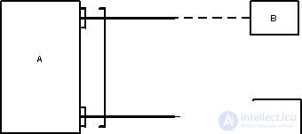
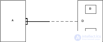
A relationship is a graphically depicted association established between two entities. This association is always binary and can exist between two different entities or between an entity and itself (recursive connection). In any connection, there are two ends (in accordance with the existing pair of connected entities), each of which indicates the name of the end of the link, the degree of the end of the link (how many instances of this entity are linked), the binding nature of the link (i.e., any instance of this entity must participate in this regard).
A relationship is represented as a line connecting two entities or leading from an entity to itself. In this case, a three-point entry into the entity rectangle is used in the “docking” connection with the entity, if many (many) instances of the entity can be used for the entity, and a single-point entry, if only one instance of the entity can participate in the association. The required end of the connection is depicted as a solid line, and the optional end is shown as a broken line.
Like an entity, a relationship is a typical concept, all instances of both pairs of connected entities obey the rules of binding.
In the example shown below, the link between the entities TICKET and PASSENGER links tickets and passengers. In this case, the end of the entity with the name "for" allows you to associate with one passenger more than one ticket, each ticket must be associated with any passenger. The end of the entity with the name "has" means that each ticket can belong to only one passenger, and the passenger is not required to have at least one ticket.

Laconic oral interpretation of the diagram is as follows:
The following example depicts a recursive relationship linking the essence of a MAN with herself. The end of the relationship with the name "son" determines the fact that one father can have more than one son. The end of the connection with the name "father" means that not every person can have sons.
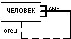
Laconic oral interpretation of the diagram is as follows:
An entity attribute is any part that serves to clarify, identify, classify, numeric, or express the state of an entity. The names of the attributes are entered in a rectangle depicting the entity, under the name of the entity and depicted in small letters, possibly with examples.
Example:
A unique identifier of an entity is an attribute, a combination of attributes, a combination of relationships, or a combination of relationships and attributes that uniquely distinguishes any entity instance from other entity instances of the same type.
As in relational database schemas, the notion of normal forms is introduced in ER schemas, and their meaning very closely matches the meaning of relational normal forms. Note that the formulations of normal forms of ER-schemes make more clear the meaning of the normalization of relational schemes. We present only very brief and informal definitions of the first three normal forms.
In the first normal form, the ER schema eliminates duplicate attributes or attribute groups, i.e. Implicit entities that are "masked" under attributes are detected.
In the second normal form, attributes that depend only on a part of the unique identifier are eliminated. This part of the unique identifier defines a separate entity.
In the third normal form, attributes that depend on attributes that are not part of a unique identifier are eliminated. These attributes are the basis of a single entity.
We dwelt only on the most basic and most obvious notions of the ER data model. The more complex elements of the model include the following:
These and other more complex elements of the Essence-Link data model make it significantly more powerful, but at the same time somewhat complicate its use. Of course, if you actually use ER-diagrams for database design, you need to familiarize yourself with all the possibilities.
In our lecture, we will examine in a little more detail only one of the mentioned elements - the subtype of entity.
An entity may be split into two or more mutually exclusive subtypes, each of which includes common attributes and / or relationships. These common attributes and / or relationships are explicitly defined once at a higher level. Subtypes can define their own attributes and / or relationships. In principle, subtyping can continue at lower levels, but experience shows that in most cases two or three levels are enough.
The entity on the basis of which the subtypes are determined is called the supertype. Subtypes must form a complete set, i.e. any instance of a supertype must refer to a subtype. Sometimes for completeness it is necessary to define an additional subtype OTHERS.
Example: Supertype AIRCRAFT
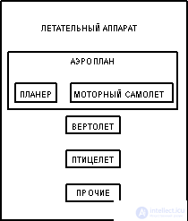
How is it supposed to read? From the supertype: AIRCRAFT, which should be an AIRPLAN, HELICOPTER, POULTRY, or OTHER AIRCRAFT. From subtype: HELICOPTER, which refers to the type of AIRCRAFT. From a subtype that is also a supertype: AIRPLAN, which belongs to the type of AIRPLANE and must be a PLANER or MOTOR AIRPLANE.
It is sometimes convenient to have two or more different partitions of an entity into subtypes. For example, the essence of a PERSON can be broken down into subtypes according to their professional characteristics (PROGRAMMER, DOYARK, etc.), and maybe according to their gender (MAN, WOMAN).
Step 1. Each simple entity turns into a table. A simple entity is an entity that is not a subtype and has no subtypes. The entity name becomes the name of the table.
Step 2. Each attribute becomes a possible column with the same name; a more accurate format may be chosen. Columns corresponding to optional attributes may contain null values; columns corresponding to mandatory attributes cannot.
Step 3. The components of the unique identifier of the entity become the primary key of the table. If there are several possible unique identifiers, the most used one is selected. If links are included in the unique identifier, a copy of the unique identifier of the entity at the far end of the link is added to the number of columns in the primary key (this process can continue recursively). For the naming of these columns, the names of the ends of links and / or the names of entities are used.
Step 4. Many-to-one (and one-to-one) relationships become foreign keys. Those. a copy of the unique identifier is made from the end of the one connection, and the corresponding columns make up the foreign key. Optional links correspond to columns that allow undefined values; required links - columns that do not allow undefined values.
Step 5. Indexes are created for the primary key (unique index), foreign keys, and those attributes on which it is supposed to basically base the queries.
Step 6. If there are subtypes in the conceptual scheme, then there are two ways:
When applying method (a), a table is created for the most external supertype, and views can be created for subtypes. At least one column containing the TYPE code is added to the table; it becomes part of the primary key.
When using method (b) for each subtype of the first level (for the lower ones, representations), the supertype is recreated using the UNION view (common columns are selected from all subtype tables — supertype columns).
| All in one table | Table - per subtype | |||||||||||||||||||||||||||||||||||||||||||||||||||||||||||||||||||||||||||||||||||||||||||||||||||||||||||||||||||||||||||||||||||||||||||||||||||||||||||||
| Benefits | ||||||||||||||||||||||||||||||||||||||||||||||||||||||||||||||||||||||||||||||||||||||||||||||||||||||||||||||||||||||||||||||||||||||||||||||||||||||||||||||
| Everything is stored together Easy access to supertype and subtype Fewer tables required | Subtyping rules are clearer Programs work only with the necessary tables. | |||||||||||||||||||||||||||||||||||||||||||||||||||||||||||||||||||||||||||||||||||||||||||||||||||||||||||||||||||||||||||||||||||||||||||||||||||||||||||||
| disadvantages | ||||||||||||||||||||||||||||||||||||||||||||||||||||||||||||||||||||||||||||||||||||||||||||||||||||||||||||||||||||||||||||||||||||||||||||||||||||||||||||||
| Too general solution Requires additional logic to work with different sets of columns and different constraints. Potential bottleneck (due to blocking) Subtype columns must be optional Some DBMSs require additional memory to store ambiguous values. | Too many tables Embarrassing columns in a UNION view Potential loss of productivity when working through UNION No modifications are possible on the supertype. | |||||||||||||||||||||||||||||||||||||||||||||||||||||||||||||||||||||||||||||||||||||||||||||||||||||||||||||||||||||||||||||||||||||||||||||||||||||||||||||
Step 7. There are two ways to work when there are exclusive links:
If the remaining foreign keys are all in the same domain, i.e. have a common format (method (a)), then two columns are created: a connection identifier and an entity identifier. The link identifier column is used to distinguish between links covered by the exception arc. An entity identifier column is used to store the values of the unique identifier of the entity at the far end of the corresponding link.
If the resulting foreign keys do not belong to the same domain, then for each link covered by the exception arc, explicit foreign key columns are created; all of these columns may contain null values.
| Shared domain | Explicit foreign keys | |||||||||||||||||||||||||||||||||||||||||||||||||||||||||||||||||||||||||||||||||||||||||||||||||||||||||||||||||||||||||||||||||||||||||||||||||||||||||||||
| Benefits | ||||||||||||||||||||||||||||||||||||||||||||||||||||||||||||||||||||||||||||||||||||||||||||||||||||||||||||||||||||||||||||||||||||||||||||||||||||||||||||||
| Only need two columns | Connection conditions - explicit | |||||||||||||||||||||||||||||||||||||||||||||||||||||||||||||||||||||||||||||||||||||||||||||||||||||||||||||||||||||||||||||||||||||||||||||||||||||||||||||
| disadvantages | ||||||||||||||||||||||||||||||||||||||||||||||||||||||||||||||||||||||||||||||||||||||||||||||||||||||||||||||||||||||||||||||||||||||||||||||||||||||||||||||
| Both optional attributes must be used in connections. | Too many columns | |||||||||||||||||||||||||||||||||||||||||||||||||||||||||||||||||||||||||||||||||||||||||||||||||||||||||||||||||||||||||||||||||||||||||||||||||||||||||||||
Alternative Entity Models:
Option 1 (bad)
Option 2 (much better if subtypes do exist) 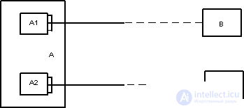
Option 3 (suitable if there is a sensible supertype D).

Comments
To leave a comment
Databases IBM System R - relational DBMS
Terms: Databases IBM System R - relational DBMS