Lecture

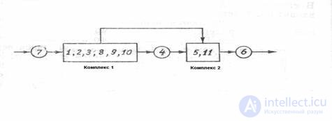
Figure 3 Definition of PPRS.
For the considered system we have: PPRS - [7, (1, 2. 3, 8, 9, 10), 4, (5, 11), 6]
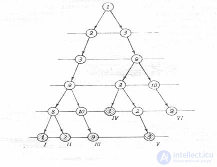
Selection of contours is made separately for each complex. One of the ways to isolate the contours is to build the tree of the complex. The pre - tree of the complex with root K is the image of all the paths existing in the complex, when only one arc enters each vertex other than K. Not a single arc enters the summit of Praderev. The construction of each path is continued until repeated vertices meet on it. In this case, the construction of the corresponding path is completed, and the last vertex is called the hanging apex of the pra-tree.
The selection of contours should be carried out in the following sequence:
Represent the structure of each complex, for example in the form of a list of links. As an example, there is a list of communication of the complex (1, 2, 3, 8, 9. 10), which is part of the CTS presented in Fig. 3
I | J | I | J | |
one | 2 | eight | one | |
one | 3 | eight | 2 | |
2 | 3 | 9 | eight | |
3 | 9 | 9 | ten | |
ten | 9 |
The construction of the complex is done. To build a tree from any vertex of the complex, which is taken as the root of the tree, all the paths that exist in the complex are constructed. Each branch is reconstructed until an existing vertex (hanging vertex) is encountered on it.
The sections of the branches of the pra-tree between the repeating vertices are the contours that make up the complex. Each hanging vertex corresponds to a contour.
In fig. Figure 5 shows the tree of the complex (1, 2, 3, 8.9, 10) (see above the corresponding link list).

Fig. 4. Selection of the contours of the complex (1.2.3.8.9.10).
Roman numerals mark the pendant vertices of the great nape.
The selected contours are entered in the contour table. Below are the contours that are part of the complex under consideration.
Table 1 . Contours included in the complex (1, 2, 3, 8, 9,10)
Hanging top | Circuit |
I, IV | 9-10-9 |
II | 1-2-3-9-8-1 |
V | 1-3-9-8-1 |
III, VI | 2-3-9-8-2 |
As can be seen from the table. 1, the total number of pendant vertices of a tree is greater than the number of different contours, since different pendant vertices can correspond to the same contour. In the complex under consideration, the pendant vertices 1 and IV correspond to the same contours 9-10-9 and to the vertices III and VI the same contours 2–3–9–8–2 and 3–9–8–2–3.
For further work out of two or several identical contours in the table of contours leave only one.
The fact that the same contours are sometimes distinguished several times is a disadvantage of the considered algorithm.
Algorithms for determining the optimal set of discontinuous flows.
From the point of view of labor-intensiveness and accuracy of calculations, it is not indifferent in which places to break the bonds of the complex. In order for the mode in open XTS to correspond to the mode in the complex, it is necessary to fulfill the condition of equality of flow parameters after the break point to the corresponding parameters up to the break point. It can be shown that this condition makes it necessary to solve a system of nonlinear equations, the total order of which is equal to the sum of the parametricities of the arcs to be broken (the parametricity or dimension of the arc is the number of parameters characterizing the corresponding process flow).
When choosing break points as the optimality criterion, the total parametricity of broken arcs can be used, that is, the sum of the unknown flow parameters at the break points.
In order to find the optimally distinct set of arcs, a matrix of contours included in the complex is built, in which the necessary information is grouped to solve the problem in question. The elements of the matrix of contours K (I, J) (1 is the number of the contour, J is the number of the arc) is determined by the following rule:
1 if arc J enters contour I | ||
K (I, J) | = | |
0 if arc J is not included in circuit I |
. The matrix of the contours of the complex (!, 2, 3, 8, 9, 10) has the form:
Contours | Dougie | ||||||||
9-10 | 10-9 | 1-2 | 2-3 | 3-9 | 9-8 | 8-1 | 8-2 | 1-3 | |
K1 (9-10-9) | one | one | 0 | 0 | 0 | 0 | 0 | 0 | 0 |
K2 (1-2-3-9-8-1) | 0 | 0 | one | one | one | one | one | 0 | 0 |
K3 (2-3-9-8-2) | 0 | 0 | 0 | one | one | one | 0 | one | 0 |
K4 (1-3-9-8-1 | 0 | 0 | 0 | 0 | one | one | one | 0 | one |
f | one | one | one | 2 | 3 | 3 | 2 | one | one |
p | one | 2 | eight | 2 | 6 | five | one | five | 2 |
We now determine the contour degree of the Jth arc f (J): it is equal to the number of contr into which this arc enters, i.e. the number of units under the arc J. The greater the contour degree of the arc, the more contours will be opened when it breaks . If f (I) = f (J), and the 1st and Jth arcs are in the same contours, then it is preferable to break the arc with less parametricity p. In our example, the parametricity of the arcs is chosen conditionally.
When finding the optimal set of torn arcs, consider the following rules:
1. The number of places of breaks must be chosen so that all the contours of the complex are broken.
2. If the parametricity of all arcs is the same, the task is reduced to determining the minimum number of arcs, the discontinuity of which turns the complex into an open subsystem. In this case, an arc with a maximum contour degree should be found. In our example, the maximum value of f has an arc of 3–9 or 9–8. The rupture of any of these arcs will lead to a decrease in the number of contours in the complex (in our case, the contours K2, CZ, and K4 will be open). Cross out these contours from the contour matrix and recalculate the contour degrees of the remaining arcs. Again we search among these arcs for an arc having a maximum contour degree, and exclude the corresponding contours. This process continues until there are no contours,
In our example, all contours can be open after breaking two arcs 3–9 and 9–10 or 9–8 and 10–9, which indicates that the solution to the problem may not be the only one.
3. In the general case, when the parametricity of the arcs of the complex is different, the broken arcs are chosen so that their total parametricity is minimal. To determine the most advantageous break points in this case, it is necessary to find all possible options for breaking arcs (subject to rule 1), determine the total parametricity of various options and find the minimum among these parametricities. The set of torn arcs with the minimum total parametricity will be optimal.
For the considered example in table. 2 presents various options for sets of torn arcs.
Table 2. Variants of sets of ruptured arcs of the complex (1, 2,3,8,9, 10)
Option number | Many broken arcs | Total parametricity |
one | 1-2.2-3.9-10.1-3 | 8 + 2 + 1 + 2 = 13 |
2 | 2-3, 9-10, 3-9 | 2 + 1 + 6 = 9 |
3 | 3-9, 9-10 | 6 + 1 = .7 |
four | 2-3., 8-1, 9-10 | 2 + 1 + 1 = 4 |
five | 2-3, 8-1, 10-9 | 2 + 1 + 2 = 5 |
6 | …………. | …………. |
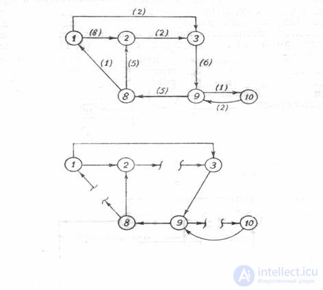
As can be seen from the table, the minimum total parametricity has many arcs (2-3, 8-1, 9-10). It is these arcs that should be broken to transform the complex into an open XTS in the example under consideration.

Fig. 5. Complex with arcs of different parametric properties and corresponding to it.
open XTS.
Comments
To leave a comment
System analysis (systems philosophy, systems theory)
Terms: System analysis (systems philosophy, systems theory)