
Lecture
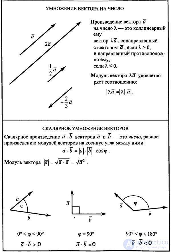
Vector (Lat. vector — that which carries).A vector is a directed line segment, that is, a segment for which it is specified which of its endpoints is the start and which is the end.
Definition. An ordered collection ( x1, x2, ... , x n ) of n real numbers is called an n-dimensional vector, and the numbers xi ( i =  ) are called components, or coordinates, of the vector.
Example. If, for instance, a certain automobile plant must produce per shift 50 passenger cars, 100 trucks, 10 buses, 50 sets of spare parts for passenger cars, and 150 sets for trucks and buses, then the plant's production program can be written as the vector (50, 100, 10, 50, 150), which has five components.
Notation. Vectors are denoted by bold lowercase letters or by letters with a bar or arrow above them, for example, a or  . Two vectors are said to be equal if they have the same number of components and their corresponding components are equal.
The components of a vector cannot be swapped: for example, (3, 2, 5, 0, 1) and (2, 3, 5, 0, 1) are different vectors.
Operations on vectors. The product of a vector x = (x1, x2 , ... ,xn) by a real number λ is the vector λ x = (λ x1, λ x2, ... , λ xn).
The sum of vectors x = (x1, x2, ... ,xn) and y = (y1, y2 , ... ,yn) is the vector x + y = (x1 + y1, x2 + y2, ... , x n+ + yn).
Vector space. The N-dimensional vector space Rn is defined as the set of all n-dimensional vectors for which the operations of multiplication by real numbers and addition are defined.
Economic illustration. An economic illustration of an n-dimensional vector space is the commodity space (space of goods). By a good we mean some benefit or service put up for sale at a certain time in a certain place. Suppose there is a finite number n of available goods; the quantities of each of them acquired by a consumer are characterized by a bundle of goods
x = (x1, x2, ..., xn),
where xi denotes the quantity of the i-th good acquired by the consumer. We assume that all goods have the property of being arbitrarily divisible, so that any non-negative quantity of each of them can be purchased. Then all possible bundles of goods are vectors of the commodity space C = { x = (x1, x2, ... , xn) xi ≥ 0, i = }.
Linear independence. A system e1, e2, ... , em of n-dimensional vectors is called linearly dependent if there exist numbers λ1, λ2, ... , λm, of which at least one is nonzero, such that the equality λ1 e1 + λ2 e2 +... + λm em = 0 holds; otherwise the given system of vectors is called linearly independent, that is, the above equality is possible only when all  . The geometric meaning of linear dependence of vectors in R3, interpreted as directed segments, is explained by the following theorems.
Theorem 1. A system consisting of a single vector is linearly dependent if and only if that vector is the zero vector.
Theorem 2. For two vectors to be linearly dependent, it is necessary and sufficient that they be collinear (parallel).
Theorem 3. For three vectors to be linearly dependent, it is necessary and sufficient that they be coplanar (lie in one plane).
Left- and right-handed triples of vectors. A triple of noncoplanar vectors a, b, c is called right-handed if, to an observer looking from their common origin, the traversal of the endpoints of the vectors a, b, c in that order appears to go clockwise. Otherwise a, b, c is a left-handed triple. All right-handed (or left-handed) triples of vectors are said to be identically oriented.
Basis and coordinates. A triple e1, e2, e3 of noncoplanar vectors in R3 is called a basis, and the vectors e1, e2, e3 themselves are called basis vectors. Any vector a can be uniquely decomposed in terms of the basis vectors, that is, represented as
a = x1 e1 + x2 e2 + x3 e3, (1.1)
the numbers x1, x2, x3 in decomposition (1.1) are called the coordinates of the vector a in the basis e1, e2, e3 and are denoted a(x1, x2, x3).
Orthonormal basis. If the vectors e1, e2, e3 are pairwise perpendicular and the length of each of them equals one, then the basis is called orthonormal, and the coordinates x1, x2, x3 are called rectangular. The basis vectors of an orthonormal basis will be denoted i, j, k.
We shall assume that a right-handed rectangular Cartesian coordinate system {0, i, j, k} has been chosen in the space R3.
Cross product. The cross product of a vector a by a vector b is the vector c, which is defined by the following three conditions:
1. The length of the vector c is numerically equal to the area of the parallelogram built on the vectors a and b, that is,
c = |a||b| sin (a^b).
2. The vector c is perpendicular to each of the vectors a and b.
3. The vectors a, b and c, taken in the given order, form a right-handed triple.
For the cross product c, the notation c = [ab] or
c = a × b is used.
If the vectors a and b are collinear, then sin(a^b) = 0 and [ab] = 0; in particular, [aa] = 0. Cross products of the unit vectors: [ij] = k, [jk] = i, [ki] = j.
If the vectors a and b are given in the basis i, j, k by the coordinates a(a1, a2, a3), b(b1, b2, b3), then

Scalar triple product. If the cross product of two vectors a and b is dot-multiplied by a third vector c, such a product of three vectors is called the scalar triple product and is denoted by the symbol a b c.
If the vectors a, b and c are given in the basis i, j, k by their coordinates
a(a1, a2, a3), b(b1, b2, b3), c(c1, c2, c3), then
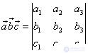 .
.
The scalar triple product has a simple geometric interpretation - it is a scalar whose absolute value equals the volume of the parallelepiped built on the three given vectors.
If the vectors form a right-handed triple, then their scalar triple product is a positive number equal to the volume indicated; if, on the other hand, the triple a, b, c - is left-handed, then a b c<0 and V = - a b c, hence V = |a b c| .
The coordinates of the vectors occurring in the problems of the first chapter are assumed to be given relative to a right-handed orthonormal basis. The unit vector codirectional with the vector a, is denoted by the symbol ao. The symbol r=OM denotes the position vector of the point M, and the symbols a, AB or |a| , |AB| denote the magnitudes of the vectors a and AB.
Example 1.2. Find the angle between the vectors a = 2m+4n and b = m-n, where m and n - are unit vectors and the angle between m and n is 120o.
Solution. We have: cos φ = ab/ab, ab = (2m+4n) (m-n) = 2 m2 - 4n2 +2mn =
= 2 - 4+2cos120o = - 2 + 2(-0.5) = -3; a =  ; a2 = (2m+4n) (2m+4n) =
= 4 m2 +16mn+16 n2 = 4+16(-0.5)+16=12, so a =  . b =
. b =  ; b2 =
= (m-n)(m-n) = m2 -2mn+ n2 = 1-2(-0.5)+1 = 3, so b =  . Finally we have: cos φ =
 = -1/2, φ = 120o.
Example 1.3. Knowing the vectors AB(-3,-2,6) and BC(-2,4,4), find the length of the altitude AD of triangle ABC.
Solution. Denoting the area of triangle ABC by S, we get:
S = 1/2 BC AD. Then AD=2S/BC, BC=  =
=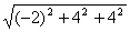 = 6,
= 6,
S = 1/2| AB × AC|. AC=AB+BC, so the vector AC has coordinates
 .
.

= -16(2  +
+  ). |AB×AC| =
  = 16
= 16 ; S = 8, whence
AD =  =
= .
.
Example 1.4. Given two vectors a(11,10,2) and b(4,0,3). Find the unit vector c, orthogonal to the vectors a and b and directed so that the ordered triple of vectors a, b, c is right-handed.
Solution. Denote the coordinates of the vector c relative to the given right-handed orthonormal basis by x, y, z.
Since c ⊥ a, c ⊥ b, we have ca = 0, cb = 0. By the condition of the problem it is required that c = 1 and a b c >0.
We have a system of equations for finding x,y,z: 11x +10y + 2z = 0, 4x+3z=0, x2 + y2 + z2 = 0.
From the first and second equations of the system we get z = -4/3 x, y = -5/6 x. Substituting y and z into the third equation, we obtain: x2 = 36/125, whence
x = ±  . Using the condition a b c >0, we obtain the inequality

Taking into account the expressions for z and y, we rewrite the resulting inequality as: 625/6 x > 0, whence it follows that x>0. So, x = , y = - , z =-
 .
.
Why do we need linear algebra?
One of the directions of study in linear algebra is the study of vectors. If your game involves positioning on-screen buttons, working with the camera and its orientation, or handling object velocities, you will have to deal with vectors. The better you understand linear algebra, the greater control you gain over the behavior of vectors and, consequently, over your game.
What is a vector?
In games, vectors are used to store positions, directions, and velocities. Below is an example of a two-dimensional vector:
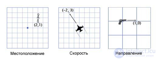
The position vector (also called a «radius vector») shows that a person is standing two meters east and one meter north of the origin. The velocity vector shows that per unit of time the airplane moves three kilometers up and two — to the left. The direction vector tells us that the gun is pointed to the right.
As you may notice, a vector by itself is just a set of numbers, which acquires one meaning or another depending on the context. For example, the vector (1, 0) could be a direction for a weapon, as shown in the picture, or the coordinates of a building one mile east of your current position. Or the speed of a snail moving to the right at 1 mile per hour (translator's note: quite fast for a snail — 44 centimeters per second).
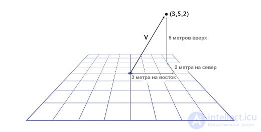
It's important to keep track of units of measurement. Suppose we have a vector V (3,5,2). This tells us little on its own. Three of what, five of what? In our game Overgrowth, distances are given in meters, and velocities in meters per second. The first number in this vector — is the eastward direction, the second — the upward direction, the third — the northward direction. Negative numbers denote the opposite directions: west, down, and south. The location specified by the vector V (3,5,2) is three meters east, five meters up, and two meters north, as shown in the picture below.
So, we've studied the basics of working with vectors. Now let's find out how to use vectors.
Vector addition
To add vectors, we simply need to add each of their components to one another. For example:
(0, 1, 4) + (3, -2, 5) = (0+3, 1-2, 4+5) = (3, -1, 9)
Why would we need to add vectors? The most common use of vector addition in games is physics integration. Any physical object will have vectors for position, velocity, and acceleration. For each frame (usually one sixtieth of a second), we need to integrate two vectors: add velocity to position and acceleration to velocity.
Let's look at an example with Mario's jump. He starts at position (0, 0). At the moment the jump begins his velocity is (1, 3), so he moves quickly up and to the right. His acceleration is (0, -1), since gravity is pulling him down. The picture shows what his jump looks like, broken down into seven frames. His velocity in each frame is shown in black text.
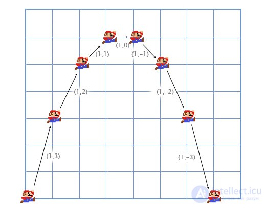
Let's look at the first frames in more detail to understand how it all works.
For the first frame, we add Mario's velocity (1, 3) to his position (0, 0) and get his new coordinates (1, 3). Then we add the acceleration (0, -1) to his velocity (1, 3) and get Mario's new velocity value (1, 2).
We do the same for the second frame. We add the velocity (1, 2) to the position (1, 3) and get the coordinates (2, 5). Then we add the acceleration (0, -1) to his velocity (1, 2) and get a new velocity of (1, 1).
Typically the player controls the acceleration of the game character using a keyboard or gamepad, while the game, in turn, computes the new values for velocity and position using physical addition (through vector addition). This is the same problem that is solved in integral calculus, we just simplify it heavily for our game. I've noticed that it's much easier for me to pay attention in integral calculus lectures when thinking about the practical application we just described.
Vector subtraction
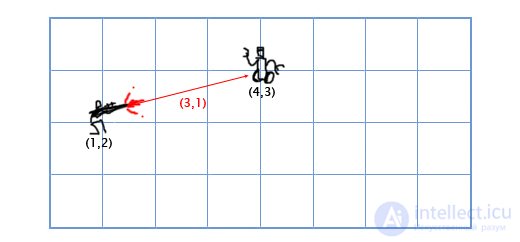
Subtraction is calculated on the same principle as addition — we subtract the corresponding components of the vectors. Vector subtraction is convenient for getting a vector that points from one location to another. For example, suppose the player is at coordinates (1, 2) with a laser gun, and an enemy robot is at coordinates (4, 3). To find the direction vector of the laser beam that will hit the robot, we need to subtract the player's position from the robot's position. We get:
(4, 3) — (1, 2) = (4-1, 3-2) = (3, 1).
Multiplying a vector by a scalar
When we talk about vectors, we call individual numbers scalars. For example (3, 4) — is a vector, and 5 — is a scalar. In games, it's often necessary to multiply a vector by a number (a scalar). For example, when simulating simple air resistance by multiplying the player's velocity by 0.9 every frame. To do this, we need to multiply each component of the vector by the scalar. If the player's velocity is (10, 20), then the new velocity will be:
0.9*(10, 20) = (0.9 * 10, 0.9 * 20) = (9, 18).
Vector length
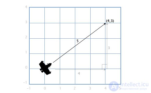
If we have a ship with a velocity vector V (4, 3), we'll also need to know how fast it's moving in order to calculate the amount of screen space needed or how much fuel is required. To do this, we need to find the length (magnitude) of the vector V. The length of a vector is denoted by vertical bars; in our case the length of the vector V will be denoted as |V|.
We can represent V as a right triangle with legs 4 and 3 and, applying the Pythagorean theorem, obtain the hypotenuse from the expression: x2 + y2 = h2
In our case — we get the length of the vector H with components (x, y) from the square root: sqrt(x2 + y2).
So, our ship's speed is:
|V| = sqrt(42 + 32) = sqrt(25) = 5
This approach is also used for three-dimensional vectors. The length of a vector with components (x, y, z) is calculated as sqrt(x2 + y2 + z2)
Distance
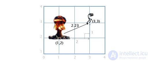
If player P is at the point (3, 3), and an explosion occurs at point E with coordinates (1, 2), we need to determine the distance between the player and the explosion in order to calculate the amount of damage dealt to the player. This is easy to do by combining the two operations described above: vector subtraction and vector length.
We subtract P — E to get the vector between them. Then we find the length of this vector, which gives us the desired distance. The order of the operands here doesn't matter, |E — P| gives the same result.
Distance = |P — E| = |(3, 3) — (1, 2)| = |(2, 1)| = sqrt(22+12) = sqrt(5) = 2.23
Normalization
When we're dealing with directions (as opposed to positions and velocities), it's important that a direction vector have a length equal to one. This greatly simplifies our life. For example, suppose a gun is oriented in the direction (1, 0) and fires a projectile at a speed of 20 meters per second. What is the velocity vector for the fired projectile in this case?
Since the direction vector has a length equal to one, we multiply the direction by the projectile's speed and get the velocity vector (20, 0). If, on the other hand, the direction vector has a length different from one, we won't be able to do this. The projectile will be either too fast or too slow.
A vector with a length equal to one is called «normalized». How do you make a vector normalized? Quite simple. We divide each component of the vector by its length. If, for example, we want to normalize the vector V with components (3, 4), we simply divide each component by its length, that is, by 5, and get (3/5, 4/5). Now, using the Pythagorean theorem, we can verify that its length equals one:
(3/5)2 + (4/5)2 = 9/25 + 16/25 = 25/25 = 1
Dot product of vectors
What is the dot product (written as •)? To calculate the dot product of two vectors, we need to multiply their components and then add the results together
(a1, a2) • (b1, b2) = a1b1 + a2b2
For example: (3, 2) • (1, 4) = 3*1 + 2*4 = 11. At first glance this seems useless, but let's look at it more closely:
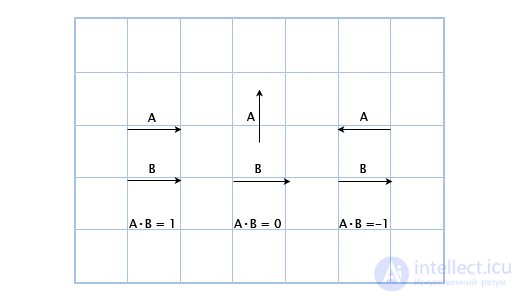
Here we can see that if the vectors point in the same direction, their dot product is greater than zero. When they are perpendicular to each other, the dot product is zero. And when they point in opposite directions, their dot product is less than zero.
Essentially, the dot product of vectors can be used to calculate how much they point in the same direction. And although this is only a small part of what the dot product can do, it's already very useful to us.
Suppose we have a guard positioned at G(1, 3) facing in the direction D(1,1), with a 180-degree field of view. The main character of the game is spying on him from position H(3, 2). How do we determine whether the main character is within the guard's field of view or not? Let's do this using the dot product of the vectors D and V (the vector pointing from the guard to the main character). We get the following:
V = H — G = (3, 2) — (1, 3) = (3-1, 2-3) = (2, -1)
D•V = (1, 1) • (2, -1) = 1*2 + 1*-1 = 2-1 = 1
Since one is greater than zero, the main character is within the guard's field of view.

We already know that the dot product is related to determining the direction of vectors. But what is its more precise definition? The mathematical expression for the dot product of vectors looks like this:
A•B = |A||B|cosΘ
Where Θ (pronounced «theta») — is the angle between vectors A and B.
This lets us find Θ (the angle) using the expression:
Θ = acos([AB] / [|A||B|])
As I said earlier, normalizing vectors simplifies our life. And if A and B are normalized, then the expression simplifies as follows:
Θ = acos(AB)
Let's look at the guard scenario again. Now let the guard's field of view be 120 degrees. Let's get normalized vectors for the guard's facing direction (D') and for the direction from the guard to the main character (V'). Then let's determine the angle between them. If the angle is more than 60 degrees (half of the field of view), then the main character is outside the guard's field of view.
D' = D / |D| = (1, 1) / sqrt(12 + 12) = (1, 1) / sqrt(2) = (0.71, 0.71)
V' = V / |V| = (2, -1) / sqrt(22 + (-1)2) = (2,-1) / sqrt(5) = (0.89, -0.45)
Θ = acos(D'V') = acos(0.71*0.89 + 0.71*(-0.45)) = acos(0.31) = 72
The angle between the center of the guard's field of view and the main character's location is 72 degrees, so the guard doesn't see him.

I understand that this looks quite complicated, but that's because we're doing everything by hand. In a program, all of this is quite simple. Below is how I did this in our game Overgrowth using C++ vector libraries I wrote:
//Initialize the vectors
vec2 guard_pos = vec2(1,3);
vec2 guard_facing = vec2(1,1);
vec2 hero_pos = vec2(3,2);

//Calculate the normalized vectors
vec2 guard_facing_n = normalize(guard_facing);
vec2 guard_to_hero = normalize(hero_pos - guard_pos);

//Calculate the angle
float angle = acos(dot(guard_facing_n, guard_to_hero));
Cross product
Suppose we have a ship with guns that fire to the right and left of its heading. Suppose the ship is oriented along the direction vector (2, 1). In which directions do the guns now fire?
This is quite simple in two-dimensional graphics. To rotate a direction 90 degrees clockwise, it's enough to swap the components of the vector, and then flip the sign of the second component.
(a, b) becomes (b, -a). Consequently, for a ship oriented along the vector (2, 1), the guns on the starboard side will fire in the direction (1, -2), and the guns on the port side will fire in the opposite direction. We flip the signs of the vector's components and get (-1, 2).
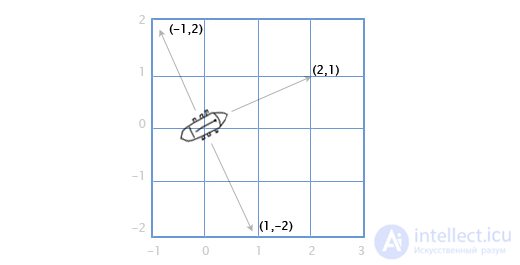
But what if we want to calculate all this for three-dimensional graphics? Let's consider the example with the ship.
We have a mast vector M, pointing straight up (0, 1, 0) and a wind direction: north-northeast W (1, 0, 2). And we want to compute the sail direction vector S so as to best «catch the wind».
To solve this problem we use the cross product: S = M x W.
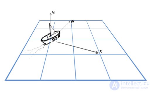
The cross product of A(a1,a2,a3) and B(b1,b2,b3) will be equal to:
(a2b3-a3b2, a3b1-a1b3, a1b2-a2b1)
Now let's substitute the values we need:
S = MxW = (0, 1, 0) x (1, 0, 2) = ([1*2 — 0*0], [0*1 — 0*2], [0*0 — 1*1]) = (2, 0, -1)
Doing this by hand is quite difficult, but for graphics and game applications I recommend writing a function like the one below and not going into further detail on such calculations.
vec3 cross(vec3 a, vec3 b) {
    vec3 result;
    result  = a  * b  - a  * b ;
    result  = a  * b  - a  * b ;
    result  = a  * b  - a  * b ;
    return result;
}
The cross product is often used in games to calculate surface normals — the direction a given surface is «facing». For example, consider a triangle with vertex vectors A, B, and C. How do we find the direction the triangle is «facing», that is, the direction perpendicular to its plane? This seems complicated, but we already have a tool to solve this problem.
Let's use subtraction to find the direction from A to C (C − A) and call this «Edge 1», and the direction from A to B (B − A) and call this «Edge 2». Then we apply the cross product to find a vector perpendicular to both of them, that is, perpendicular to the plane of the triangle, also called the «surface normal».
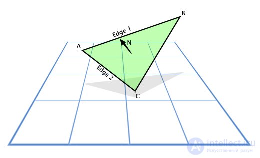
Here's what that looks like in code:
vec3 GetTriangleNormal(vec3 a, vec3 b, vec3 c) {
    vec3 edge1 = b-a;
    vec3 edge2 = c-a;
    vec3 normal = cross(edge1,edge2);
    return normal;
}
In games, the basic lighting expression is written as N • L, where N is the normal to the illuminated surface, and L is the normalized light direction vector. As a result, the surface appears bright when light falls directly on it, and dark when it doesn't.
Now let's move on to a concept that's very important for game developers — the «transformation matrix».
First, let's look at the «building blocks» of the transformation matrix.
Basis Vector
Suppose we're writing an Asteroids game on very old «hardware» and we need a simple two-dimensional spaceship that can freely rotate in its own plane. The ship model looks like this:
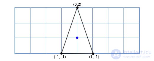
How do we draw the ship when the player rotates it by an arbitrary angle, say 49 degrees counterclockwise? Using trigonometry, we can write a two-dimensional rotation function that takes a point's coordinates and a rotation angle, and returns the coordinates of the rotated point:
vec2 rotate(vec2 point, float angle){
           vec2 rotated_point;
           rotated_point.x = point.x * cos(angle) - point.y * sin(angle);
           rotated_point.y = point.x * sin(angle) + point.y * cos(angle);
           return rotated_point;
}
Applying this function to all three points, we get the following picture:
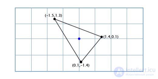
Sine and cosine operations are fairly slow, but since we're only doing the calculations for three points, this will run fine even on old «hardware» (translator's note: when trigonometric functions are expected to be used intensively, lookup tables of values for each function are typically built in memory and computed at application startup to speed up computation; then, whenever a given trigonometric function needs to be evaluated, the table is simply looked up instead).
Now suppose our ship looks like this:
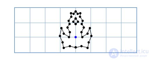
Now the old approach will be too slow, since we'd have to rotate a fairly large number of points. One elegant solution to this problem sounds like this — «What if, instead of rotating each point of the ship model, we rotate the coordinate grid of our model?»
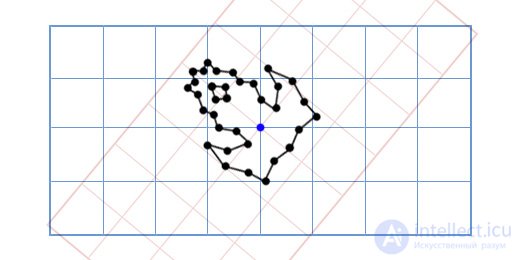
How does this work? Let's take a closer look at what coordinates actually represent.
When we talk about a point with coordinates (3, 2), we mean that its location is three steps from the origin along the X coordinate axis, and two steps from the origin along the Y coordinate axis.
By default, the coordinate axes are positioned like this: the X-axis vector is (1, 0), and the Y-axis vector is (0, 1). This gives us the position 3(1, 0) + 2(0, 1). But the coordinate axes don't have to stay in this position. If we rotate the coordinate axes, we simultaneously rotate every point in the coordinate grid.
To get the rotated X and Y axes, we apply the trigonometric functions discussed above. If we rotate by 49 degrees, the new X axis is obtained by rotating the vector (1, 0) by 49 degrees, and the new Y axis is obtained by rotating the vector (0, 1) by 49 degrees. So the new X-axis vector will be (0.66, 0.75), and the new Y-axis vector will be (-0.75, 0.66). Let's do this by hand for our simple three-point model, to make sure it works the way it should:
The coordinates of the top point are (0, 2), meaning its new location is 0 on the new (rotated) X axis and 2 on the new Y axis:
0*(0.66,0.75) + 2*(-0.75, 0.66) = (-1.5, 1.3)
The bottom-left point is (-1, -1), meaning its new location is -1 on the rotated X axis and -1 on the rotated Y axis:
-1*(0.66,0.75) + -1*(-0.75, 0.66) = (0.1, -1.4)
The bottom-right point is (1, -1), meaning its new location is 1 on the rotated X axis and -1 on the rotated Y axis
1*(0.66,0.75) + -1*(-0.75, 0.66) = (1.4, 0.1)
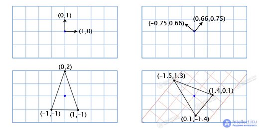
We've shown how the ship's coordinates map onto a different coordinate grid with rotated axes (or «basis vectors»). This is convenient in our case, since it saves us from having to apply trigonometric transformations to each point of the ship model.
Every time we change the basis vectors (1, 0) and (0, 1) to (a, b) and (c, d), the new coordinate of a point (x, y) can be found using the expression:
x(a,b) + y(c,d)
Usually the basis vectors are (1, 0) and (0, 1), and we simply get x(1, 0) + y(0, 1) = (x, y), so there's no need to worry about this any further. However, it's important to remember that we can use other basis vectors whenever we need to.
Matrices
Matrices are similar to two-dimensional vectors. For example, a typical 2x2 matrix might look like this:
   [a c
    b d]
When you multiply a matrix by a vector, you sum the dot product of each row with the vector being multiplied. For example, if we multiply the matrix above by the vector (x, y), we get:
(a,c)•(x,y) + (b,d)•(x,y)
Written another way, this expression looks like this:
x(a,b) + y(c,d)
Looks familiar, doesn't it? This is exactly the same expression we used for changing basis vectors. This means that multiplying a 2x2 matrix by a two-dimensional vector changes the basis vectors. For example, if we plug the standard basis vectors (1, 0) and (0, 1) into the columns of the matrix, we get:
[1 0
 0 1]
This is the identity matrix, which doesn't produce any effect — as we'd expect from the neutral basis vectors we specified. If we rotate the basis vectors by 49 degrees, we get:
[0.66 -0.75
 0.75  0.66]
This matrix will rotate a two-dimensional vector by 49 degrees counterclockwise. We can make our Asteroids game code more elegant by using matrices like this one. For example, our ship's rotation function might look like this:
void RotateShip(float degrees){
        Matrix2x2 R = GetRotationMatrix(degrees);
        for(int i=0; i
However, our code would be even more elegant if we could also incorporate the ship's translation in space into this matrix. Then we'd have a single data structure that holds and applies information about both the object's orientation and its position in space. Fortunately, there's a way to achieve this, even though it doesn't look very elegant. If we want to translate by a vector (e, f), we simply fold it into our transformation matrix:
[a c e
 b d f
 0 0 1]
And we add an extra one to the end of each vector that defines the object's position, like this:
[x y 1]
Now, when we multiply them, we get:
(a, c, e) • (x, y, 1) + (b, d, f) • (x, y, 1) + (0, 0, 1) • (x, y, 1)
Which, in turn, can be written as:
x(a, b) + y(c, d) + (e, f)
Now we have a complete transformation mechanism packed into a single matrix. This matters beyond mere code elegance, because it lets us use all the standard matrix manipulations. For example, we can multiply matrices together to combine effects, or invert a matrix to get the exact opposite position of the object.
Three-Dimensional Matrices
Matrices in three-dimensional space work the same way as in two dimensions. I've been using two-dimensional vectors and matrices in the examples because they're easy to display on a screen that shows a two-dimensional picture. We just need to define three columns for the basis vectors instead of two. If the basis vectors are (a,b,c), (d,e,f) and (g,h,i) then our matrix will look like this:
[a d g
 b e h
 c f i]
If we need a translation of (j,k,l), we add an extra column and row, as we did before:
[a d g j
 b e h k
 c f i l
 0 0 0 1]
And we add a one to the vector, like this:
[x y z 1]
Rotation in Two-Dimensional Space
Since in our case there's only one axis of rotation (perpendicular to the screen), the only thing we need to know is the angle. I mentioned this earlier, noting that we can use trigonometric functions to implement a two-dimensional rotation function like this one:
vec2 rotate(vec2 point, float angle){
        vec2 rotated_point;
        rotated_point.x = point.x * cos(angle) - point.y * sin(angle);
        rotated_point.y = point.x * sin(angle) + point.y * cos(angle);
        return rotated_point;
}
This can be expressed more elegantly in matrix form. To define the matrix, we can apply this function to the axes (1, 0) and (0, 1) for an angle Θ, and then place the resulting axes into the columns of our matrix. So, let's start with the X coordinate axis (1, 0). If we apply our function to it, we get:
(1*cos(Θ) − 0*sin(Θ), 1*sin(Θ) + 0*cos(Θ)) = (cos(Θ), sin(Θ))
Next, we include the Y coordinate axis (0, 1). We get:
(0*cos(Θ) − 1*sin(Θ), 0*sin(Θ) + 1*cos(Θ)) = (-sin(Θ), cos(Θ))
We plug the resulting coordinate axes into the matrix and get the two-dimensional rotation matrix:
[cos(Θ) -sin(Θ)
 sin(Θ)  cos(Θ)]
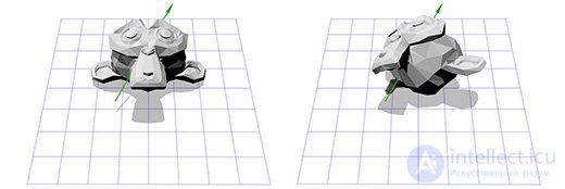
Let's apply this matrix to Suzanne, the monkey mascot from the Blender graphics package. The rotation angle Θ is 45 degrees clockwise.
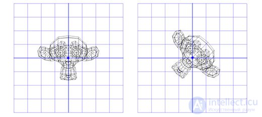
As you can see, it works. But what if we need to rotate around a point other than (0, 0)?
For example, suppose we want to rotate the monkey's head around a point located at its ear:
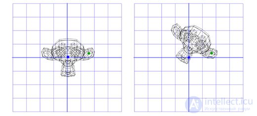
To do this, we can start by creating a translation matrix T that moves the object from the origin to the rotation point at the monkey's ear, and a rotation matrix R for rotating the object around the origin. Now, to rotate around the point at the ear, we can first move the ear point to the origin by inverting matrix T, written as T-1. Then we rotate the object around the origin using matrix R, and finally apply matrix T to move the rotation point back to its original position.
Below is an illustration of each of the steps described:
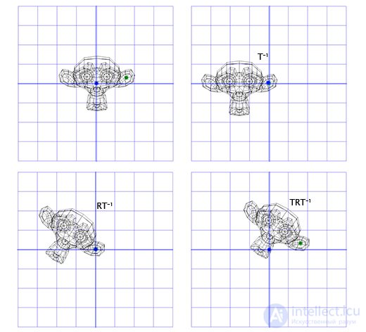
This is an important pattern that we'll use later — applying rotation between two opposite transformations lets us rotate an object in a different «space». This is very convenient and useful.
Now let's look at three-dimensional rotation.
Three-Dimensional Rotation
Rotation around the Z axis works on the same principle as rotation in two-dimensional space. We just need to change our old matrix by adding an extra column and row:
[cos(Θ) -sin(Θ) 0
 sin(Θ)  cos(Θ) 0
 0       0      1]
Let's apply this matrix to the three-dimensional version of Suzanne, the monkey from the Blender package. Let the rotation angle Θ be 45 degrees clockwise.
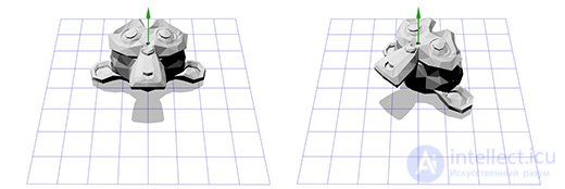
Same result. But rotating only around the Z axis limits us — what about rotating around an arbitrary axis?
Rotation Defined by an Axis and an Angle (Axis-angle rotation)
Axis-angle rotation, also known as rotation in exponential coordinates, is parameterized by two quantities: a vector defining the rotation axis (a straight line), and an angle describing the amount of rotation about that axis. The rotation follows the right-hand rule.
So, the rotation is given by two parameters (axis, angle), where axis is the rotation axis vector, and angle is the rotation angle. This approach is fairly simple and serves as the starting point for many of the other rotation operations I work with. How do we actually apply an axis-angle rotation in practice?
Suppose we're dealing with the rotation axis shown in the figure below:
We know how to rotate an object around the Z axis, and we know how to rotate an object in other spaces. So all we need to do is create a space in which our rotation axis is the Z axis. And if that axis is the Z axis, what will the X and Y axes be? Let's work that out now.
To create the new X and Y axes, we just need to pick two vectors that are perpendicular to the new Z axis and perpendicular to each other. We already talked earlier about the cross product, which takes two vectors and produces a vector perpendicular to both of them.
We already have one vector right now — the rotation axis; let's call it A. Now let's take some other, arbitrary vector B that doesn't point in the same direction as A. Let's say it's (0, 0, 1), for example.
Now that we have the rotation axis A and the arbitrary vector B, we can get a normal C by taking the cross product of A and B. C is perpendicular to both A and B. Now we make B perpendicular to both A and C by taking their cross product. And that's it — we now have all the coordinate axes we need.
This sounds complicated in words, but it's fairly simple in code, or when shown in pictures.
Here's what it looks like in code:
B = (0,0,1);
C = cross(A,B);
B = cross(C,A);
Here's an illustration of each step:
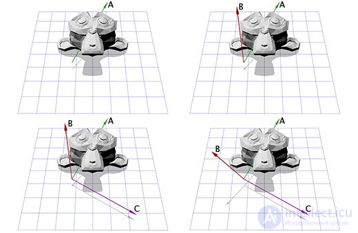
Now that we have the new coordinate axes, we can build matrix M by putting each axis in as a column of that matrix. We need to make sure vector A is the third column, so that it becomes our new Z coordinate axis.
[B0 C0 A0
 B1 C1 A1
 B2 C2 A2]
Now this is similar to what we did for rotation in two-dimensional space. We can apply the inverted matrix M to move into the new coordinate system, then perform the rotation using matrix R to rotate the object around the Z axis, and then apply matrix M to return to the original coordinate space.
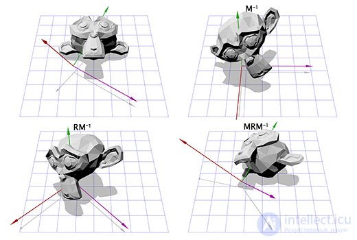
Now we can rotate an object around an arbitrary axis. In the end, we can simply build the matrix T = M-1RM and reuse it many times without any extra effort on our part. There are more efficient ways of converting axis-angle rotations into matrix rotations. The approach we've just described simply illustrates much of what we've talked about so far.
Axis-angle rotation is probably the most intuitive method. Using it, it's very easy to invert a rotation by flipping the sign of the angle, and easy to interpolate by interpolating the angle. However, there's a serious limitation here: this kind of rotation isn't additive. That is, you can't combine two axis-angle rotations into a third one.
Axis-angle rotation is a good place to start, but it needs to be converted into something else to be used in more complex cases.
Euler Angles
Euler angles are another way of representing rotation, consisting of three nested rotations about the X, Y, and Z axes. You've probably encountered them in games, where the camera shows the action from a first-person or third-person view.
Suppose you're playing a first-person shooter, and you turn 30 degrees to the left and then look 40 degrees up. Finally, you get shot and hit, and as a result of the impact, the camera rolls 45 degrees around its own axis. Below is the rotation represented using Euler angles (30, 40, 45).
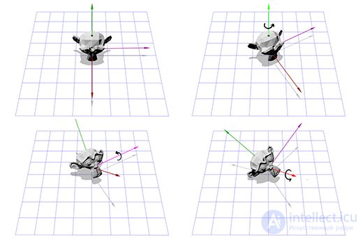
Euler angles are a convenient and easy-to-control tool. But this method has two drawbacks.
The first is the possibility of a situation called «axis lock» or «gimbal lock». Imagine you're playing a first-person shooter where you can look left, right, up, and down, or roll the camera around the view axis. Now imagine you're looking straight up. In this situation, trying to look left or right becomes equivalent to trying to roll the camera. All we can do in this case is roll the camera around its own axis or look back down. As you can imagine, this limitation makes Euler angles impractical for use in flight simulators.
The second is that interpolation between two Euler angle rotations doesn't give the shortest path between them.
For example, suppose you have two interpolations between the same two rotations. The first uses Euler angle interpolation, and the second uses spherical linear interpolation (SLERP) to find the shortest path.
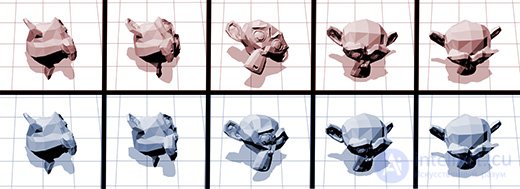
So what's better suited for interpolating rotations? Maybe matrices?
Rotation Using Matrices
As we mentioned earlier, rotation matrices store information about three axes. This means that interpolating between two matrices only linearly interpolates each axis. As a result, this gives us an efficient path, but it also introduces new problems. For example, here are two rotations and one interpolated half-rotation:
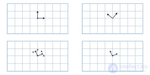
As you can see, the interpolated rotation is noticeably smaller than either of the original rotations, and the two axes are no longer perpendicular to each other. This makes sense if you think about it — the midpoint of the segment connecting any two points on a sphere lies closer to the center of the sphere.
This, in turn, produces the well-known «candy wrapper effect» when using skeletal animation. Below is a demonstration of this effect on the rabbit from our game Overgrowth (translator's note: pay attention to the middle of the rabbit's torso).
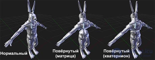
Rotation based on matrix operations is very useful, since matrices can accumulate rotations without any issues like gimbal lock, and can be applied very efficiently to scene points. This is why hardware support for matrix rotation is built into graphics cards. For any type of three-dimensional graphics, the matrix rotation format is always the final format that gets applied.
However, as we already know, matrices don't interpolate very well, and they aren't very intuitive.
So there's only one major rotation format left. Last, but by no means least.
Quaternions
So what exactly are quaternions? Put very briefly, they're an alternative rotation format based on axis-angle rotation, existing in four-dimensional space.
Like matrices, they can accumulate rotations, meaning you can chain rotations together without worrying about gimbal lock. At the same time, unlike matrices, they interpolate well from one orientation to another.
Are quaternions a better solution than the other rotation formats?
In many ways, they combine the strengths of all the other rotation formats. But they have two weaknesses, and once we look at them, we'll conclude that quaternions are best used for intermediate rotations. So, what are the drawbacks of quaternions?
First, quaternions aren't easy to visualize in three-dimensional space. Because of this, we're always forced to implement a rotation using a simpler method first, and then convert it. Second, quaternions can't efficiently rotate points, so we have to convert them into matrices in order to rotate a large number of points.
This means you probably won't start or end a series of rotations with quaternions. But you can use them to implement intermediate rotations more efficiently than with any other approach.
«The inner workings» of the quaternion mechanism aren't very clear to me, nor am I particularly interested in them. And they probably won't interest you either, unless you're a mathematician. I'd recommend finding libraries that work with quaternions, to make it easier to solve your problems with them.
продолжение следует...
Часть 1 Vectors in Linear Algebra and Programming

Comments