Lecture
As was shown above (see The contribution of informative features), the contribution of recognition features depends on both the power of the features themselves and the signal-to-noise ratio. This should be clear.
Even with large signs of power, recognition capabilities cannot be realized if the required signal-to-noise ratio is not met. In fig. 8. Some variants of feature regions for signal-to-noise ratio 1 and 0.1 are shown with equilibrium signs of target and interference. It illustrates how important the signal-to-noise ratio is. Even with the equilibrium value of the power of the signs of the target and interference, the total contribution of the signs (increment) for recognition becomes insignificant if the signal-to-noise ratio is small.
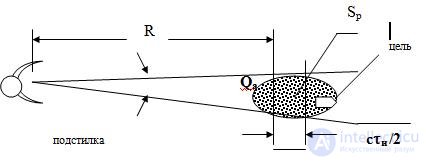
In turn, the signal-to-noise ratio is determined by the radar resolution in range and direction. Figure 2 shows the principle
Formation of the signal / passive interference ratio.

Fig.9. Formation of the signal / interference ratio.
( c is the speed of light, S p is the radar resolution element, R is the distance to the target, Q a - antenna beamwidth, t and - equivalent pulse duration)
In fig. 9. given the formation of the signal-to-passive interference
when locating a ground target with an effective scattering surface s c [m 2 ], standing in the background of some underlying surface with a specific effective scattering surface g p [m 2 / m 2 ] . The signal-to-noise ratio p c / p p is easy to calculate if the source data is known.
p c / p p " s c / g p [ RQ a c t and / 2] (sixteen)
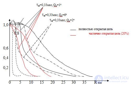
In fig. 10. shows the loss curves of informative features of the target against the background of various underlying surfaces. The “traditional” duration of the probing radar signal t and = 0.33 μs is taken. This is equivalent to the duration of a compressed pulse for a radar with a complex signal, or the autocorrelation function of the correlation processing channel. The same can be obtained with frequency carrier pumping within 4 MHz.

Fig.10. Graphs of loss of informative signs of signals
The figure shows two curves for each option 1, 2 and 6-degree width of the antenna beam. The upper curve corresponds to the “light” underlying surface (meadow with fine grass, shallow arable land with specific scattering surface of 10 -3 m 2 / m 2 ). The lower curve for the underlying surface is “medium gravity” (10 -2 m 2 / m 2 ).
In the computational model it was considered that if the signal-to-noise ratio is greater than one, then there is no loss of information content. It did not take into account such possible complications of situations as the use of absorbing paints, capes, as well as unmasking techniques, such as installing plant imitation devices on the object, by a potential adversary .
Analyzing the graphs, it is possible to note a significant drop in the information content of the signal on relatively large for ground-based radar ranges, which can lead to physical impossibility of recognition.
To reduce the loss of symptoms can be a significant narrowing of the DNA. However, with the limit of the geometric dimensions of the antennas, one way remains - the use of mm waveband, which is not always convenient due to signal loss at long ranges, not enough high efficiency of microwave devices and paths.
Another possibility to reduce the loss of informativity can be the expansion of the effective signal spectrum up to 10-30 MHz due to shortening of the compressed pulse, or frequency pumping of the carrier and special processing of the reflected signal. However , finding a rational solution requires resources and time.
Findings:
1. Informative features in a signal reflected from a real target may be lost due to the influence of the underlying surface. The level of losses, even with linear processing, may be such that recognition becomes impossible.
2. With the overall limitations of the antenna, the reduction of informative losses can be carried out by using mm wavelength range (at distances up to 10 km), and due to the equivalent expansion of the width of the probe signal spectrum.
Comments
To leave a comment
Radio Engineering Systems
Terms: Radio Engineering Systems