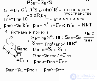
Intentional interference may not allow the object to be investigated. They can dramatically reduce the range of the radar. The most common noise interference average power p p from 0.2 to 10 kW. This power can be concentrated in a narrow? F pom and wide range ? F stroke frequencies. At the same time , the spectral density of interference
n pom 2 may increase or decrease accordingly. It is difficult to protect yourself from disturbances entering the main lobe of the DNA. But hindrance in one narrow main lobe is difficult. Therefore, the jamming strategy is based on the idea of hitting the side lobes, which are many. If the effective area of the antenna is S a , then the effective level of side lobes S ab can be calculated by the percentage of lateral b % . S ab = S a b % / 100
Electronic warfare systems incorporate panoramic reconnaissance receivers, which quite quickly determine the operating frequency of the radar f , duration? and and the type of probing signal. From here is determined the band of the receiving path , The jammer is tuned for intelligence and generates targeted interference. If the radar tunes the wave, then the new frequency is reconnoitered , and the transmitter is tuned. If the radar has a fast frequency tuning and the jammer does not have time to keep track of the production, then he is forced to use a barrier with significantly lower spectral density levels.
n pom 2 = p pom / ? F pom
for sighting noise? F pom ? one/ ? and for overseas ? F pom =? F stroke
Essentially, the noise interference adds a certain noise power to the reduced receiver noise , which reduces the signal-to-noise ratio. The new power of the reduced noise at the input of R CR = R CR + p shpo .
Flux density interference power ? by At the input of the radar antenna can be calculated by the radio equation, as shown in Fig.1. To do this, you need to know the distance to the producer R , the transmitter power p by and its antenna gain G apo . These data are usually known or entered on tactical or other grounds.

Fig.1 Power interference
It is not superfluous to recall that the action of the radar is ensured by a given ratio of the signal level, p apr , to the noise level of the receiver p w . Active noise interference dramatically increases the noise level, which leads to a sharp decrease in the range of the radar, and as a result - to the failure to perform the tasks. In Figure 1 . derived equation of active interference. The conclusion is based on the calculation of the signal power from the target and the total power of the reduced noise.
It is believed that the radar can always be suppressed by the main lobe. Therefore, the calculation is carried out on the side lobes of the DND, which have a known average level in percent relative to the main one. To understand the logic of the derivation of the equation, it is advisable to recall the derivation of the radar equation. There are the same designations. The “ Range ” software package is able to calculate how interference is affected. To do this, enter the range to the director,
Anti-jamming
one. Fast frequency tuning of the probing signal.
This technique has already been discussed above.
2 Decrease in level of side lobes.
3 The use of correlation compensators.
The essence of the method is as follows. In addition to the main antenna, additional antennas are installed on the radar, the diagram of which is consistent with the side lobes of the main antenna. Autocompensator antennas accept interference, calculate its power and, simplifyingly speaking, subtract it from interference received by the side lobe.
four. Receivers SHOW
Barrier interference on orders of magnitude wider than the bandwidth of the receiver. Therefore, if in a broadband (W) amplifier band? F sh to make a restriction (O) in amplitude, and after it put the narrowband filter (V) in a band? F y , matched with the reflected signal, the signal-to-noise ratio will improve by k show times.
k show =? F w /? F y

Fig.2 Receiver SHOW


Comments
To leave a comment
Radio Engineering Systems
Terms: Radio Engineering Systems